

Vernier Optics Expansion Kit User Manual
Optics
NOTE: Vernier products are designed for educational use. Our products are not
designed nor recommended for any industrial, medical, or commercial process such
as life support, patient diagnosis, control of a manufacturing process, or industrial
testing of any kind.
Expansion Kit
(Order Code OEK)
The Vernier Optics Expansion Kit
(OEK) is a set of lenses, holders, a light
source, a sensor holder, aperture plate,
and a screen for use with the Vernier
Track. The required Track is available
separately or as a part of the Vernier Dynamics System. Students can perform basic
optics experiments with this equipment. Some typical experiments done with the
system include
Thin lens image formation from a converging lens
Thin lens equation
Image formation by a convex lens
Focal length measurement
Simple telescope construction
Microscope
Inverse-square law of light intensity from a point source
Lens diameter and shape effects on image
The OEK requires the addition of a Vernier Light Sensor, an interface, and a
data-collection application for performing the inverse-square experiment.
Appropriate interfaces include the Vernier LabQuest
interfaces, the Vernier Go!
software includes Logger Pro
original LabQuest, EasyData™ and DataMate™ for calculators, and DataQuest™
for the TI-Nspire™.
®
Link, and the Texas Instruments CBL 2™. Appropriate
®
for computers, LabQuest App for LabQuest 2 or the
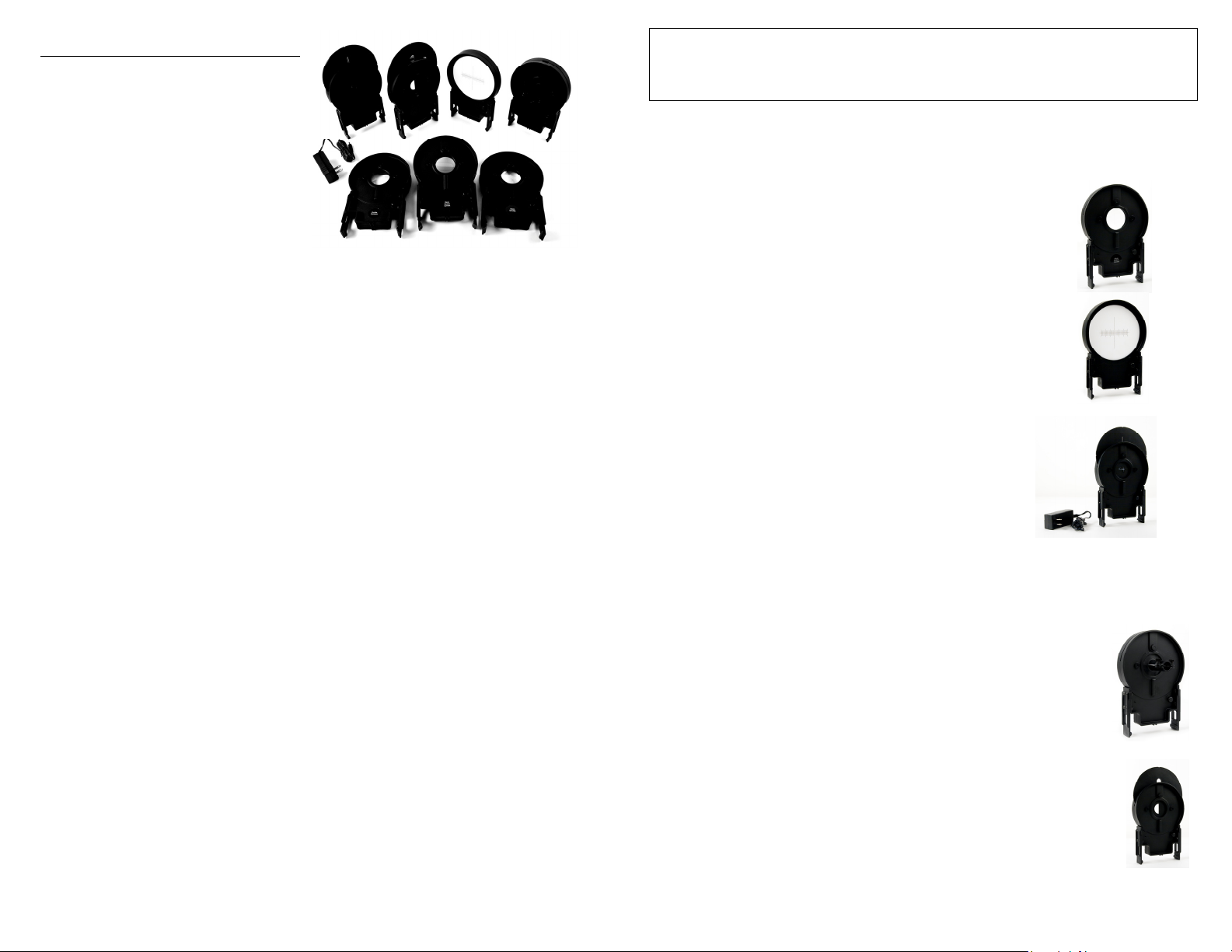
What is included with the Optics Expansion Kit?
The Optics Expansion Kit is shipped in one box containing the following parts:
Light source with power supply
Screen with holder
Light sensor holder
Aperture disc and holder
100 mm focal length double convex lens in holder
200 mm focal length double convex lens in holder
–150 mm focal length double concave lens in holder
®
2, LabQuest, or LabPro®
Common Holder Design
The lens holders, screen holder, aperture plate, light source and light sensor holder
all use similar plastic holders. These holders snap to the track with a slight pull to the
side. The base unit has fiducial marks to locate the center line of
a screen, sensor, light or lens held by the base. Read the scale on
the track through the hole in the base unit.
Lens Holders
The lens holders have the lenses permanently mounted. Do not
remove the lenses.
Screen Holder Assembly
The screen is marked with a millimeter scale.
Light Source Assembly
The light source uses a single white LED. A rotating plate lets
you choose various types of light for experiments. The open hole
exposes the LED to act as a point source. The other
openings are covered by white plastic to create luminous
sources. The figure “4” is for studying image formation,
and is chosen since it is not symmetric left-right or
up-down. The “L” shape is 1 by 2 cm in size. The
double-slit is used for depth-of-field experiments.
The plane of the luminous sources is located at the
position marked by the pointer on the base. In contrast,
the LED point source is located at the back edge of the holder. This location is
important to note for accurate distances in inverse-square experiments.
The power supply provided with the OEK is the same as the power supply for
LabQuest. A rocker switch on the back of the light source turns the light on and off.
Light Sensor Holder
The light sensor holder is used to position a Vernier Light Sensor for
inverse-square law experiments. Insert a Vernier Light Sensor until it
reaches the stop. The location of the sensor can then be read from the
arrows on the base.
Aperture Disc
An aperture disc can be placed immediately adjacent to a lens in order to
vary the effective diameter and shape of the lens. Experiments regarding
f/stop and brightness can thus be performed. A D-shaped aperture allows
the “half a lens” demonstration to be performed.
2
Sample Experiments: Real Image Formation
The thin lens equation is
111
oif
where f is the lens focal length, i is the image to lens distance, and o is the object to
lens distance. Sign convention for f is positive for converging lenses, negative for
diverging. The variable i is positive if the (real) image is in back of the lens, and
negative if the (virtual) image is in front. The variable o is positive if the (real) object
is in front of the lens, and negative if the (virtual) object is behind the lens.
This relationship can be verified using the Optics
Expansion Kit. Place the light source near the end
of the track, with the luminous source facing along
the longer length of the track. Insert the 100 mm
focal length lens into a holder, and place it 15 cm
from the light source plane. Place the screen on the
side of the lens opposite the light source. Where do
you find a sharp image? Is it where you expect it
using the thin lens equation?
The linear magnification M of a lens is
h
i
M
where h
height of the image and object. Does the linear magnification you observe match the
prediction?
is the image height, and ho is the object height. Use a ruler to measure the
i
i
h
o
o
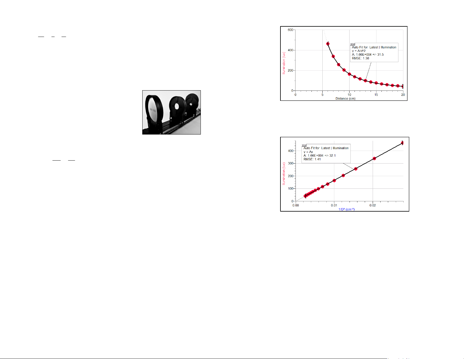
Collect intensity data as a function of distance. Sample data with curve fits are
shown in the following two graphs.
The light intensity follows the expected inverse-square relationship well. Another
way to show this relationship is to graph light intensity vs. the inverse of the squared
distances. The resulting graph should be a direct proportionality. The next graph
shows this result.
Sample Experiments: Inverse Square Law
This experiment requires a light sensor, interface, and associated software. In this
example we will use Logger Pro software, a Go! Link, and a Vernier Light Sensor.
Position the light source so that the LED is exposed and is facing down the length of
the track. Read the position using the back edge of the carriage for the light source.
Attach a light sensor to the light sensor holder. Insert a Vernier Light Sensor until it
reaches the stop. The location of the sensor can then be read from the arrows on the
base. Position the sensor so it is pointing directly at the light source. Allow the light
source to stabilize for 15 minutes before collecting data. The intensity falls slightly
as the LED warms, so for this experiment, warm-up time is required.
3
The room was partially darkened during data collection. If there is substantial
background light, both graphs would be shifted upward, and the fits would require
an additive term.
Additional Experiments
Make a telescope by combining convex lenses at the sum of focal lengths.
Study the effect of lens size and shape on image formation. Set up the luminous
source, a converging lens, and the screen so that you see a real image on the
screen. Position the aperture plate as close to a lens as possible, and observe the
effect of different size apertures. You may need to dim the room lights to see the
changes. What will happen with the D-shaped opening?
Study depth-of-field by casting a real image of the two slits on the screen, and
then take it out of focus by moving the screen until you can no longer resolve the
two lines. Use the aperture plate to make the working diameter of the lens
smaller. How does this change the image?
4
 Loading...