

Page 1
Vernier Motion
Encoder System
(Order Code: VDS-EC)
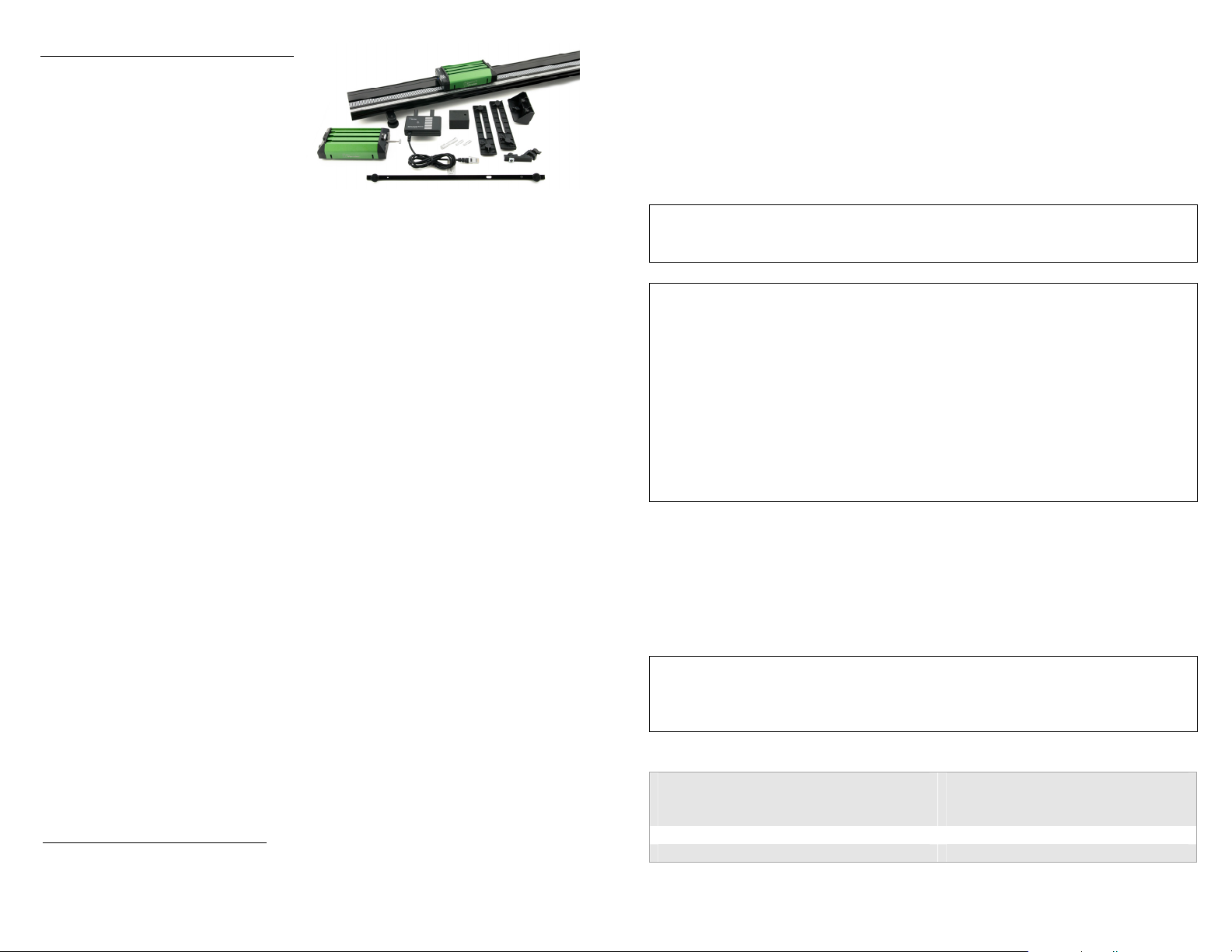
The Vernier Motion Encoder System
is a Vernier Dynamics System outfitted
for the precise study of dynamics cart motion without the use of ultrasonic motion
detectors. The encoder system consists of several parts:
A track with an encoder strip along the length of the track
A dynamics cart with an optical encoder and infrared (IR) transmitter
A receiver, attached to the end of a track
The encoder strip consists of alternating black and white bars with a 4 mm period,
allowing the optical sensor to detect the passage of the bars as the cart moves. With
two sensors appropriately placed, a change in position with 1 mm resolution can be
determined, as well as the direction of travel. A narrow infrared beam transmits
motion data to a receiver.
No alignments or adjustments are necessary, as the receiver attaches firmly to the
track, and the cart rides in slots on the track. The IR beam is not disturbed by
reflections from nearby objects.
The system is designed for use in physics and physical science courses for motion
and energy experiments. An optional Optics Expansion Kit (order code: OEK)
converts the track to an optics bench.
Some typical experiments done with the system include
Motion under zero acceleration
Motion under constant acceleration with the ramp inclined
Inelastic collisions using the included hook-and-pile tabs
Elastic collisions using the included magnetic bumpers
Parts Included with the Vernier Motion Encoder System
Motion Encoder Cart with magnetic and hook-and-pile end caps
Motion Encoder Receiver
Plunger Cart with magnetic and hook-and-pile end caps
Mass – 500 g
Combination 1.2 m dynamics track/optics bench with encoder strip
Adjustable leveling feet
Mounting hardware for Dual-Range Force Sensor and accelerometers
Adjustable End Stop
Motion Detector Bracket
*
Patent Pending
*
2 Photogate Brackets
Rod Clamp
Allen wrench 3/32 inch
Collect Data with the Vernier Motion Encoder System
This sensor can be used with the following interfaces to collect data:
Vernier LabQuest
Vernier LabQuest
Vernier LabPro
WARNING: The Motion Encoder Receiver is not compatible with the Texas
Instruments TI-Nspire Lab Cradle. Connecting the Receiver to the Lab Cradle will
render the Cradle inoperative, requiring repair by Texas Instruments.
Essential steps for using the Vernier Motion Encoder System:
1. Attach the receiver to the end of the track, matching the encoder strip on the track
to the markings on the receiver.
2. Place the track on a level surface.
3. Insert two AAA batteries (not included) into the encoder cart.
4. Connect the receiver to an interface such as a LabQuest 2. If using a computer,
connect the interface to your computer, and launch Logger Pro.
5. Turn on the cart by pressing the power button. It will glow blue when the cart is
on.
6. Place the cart on the track, wheels in grooves, with the blue light facing the
receiver.
7. Begin data collection, and let the cart roll.
®
as a standalone device or with a computer
®
Mini with a computer
®
with a computer
Data-Collection Software
This sensor can be used with an interface and the following data-collection software.
Logger Pro 3 This computer program is used with LabQuest or LabPro.
Version 3.8.6.2 or newer is required.
LabQuest App This program is used when LabQuest is used as a standalone
device. Versions 1.7.1 for the original LabQuest and 2.2.1 for the LabQuest 2,
or newer, are required.
NOTE: Vernier products are designed for educational use. Our products are not
designed nor are they recommended for any industrial, medical, or commercial
process such as life support, patient diagnosis, control of a manufacturing process, or
industrial testing of any kind.
Specifications
Measurement Range
1 m range
2 m range
Accuracy and Resolution 1 mm
Optimum data-collection rate 15–30 Hz
1.2 m track
2.2 m track
2
Page 2

Calibration of the Vernier Motion Encoder System
This sensor is equipped with circuitry that supports auto-ID. When used with
LabQuest, LabQuest 2, or LabQuest Mini, the data-collection software identifies the
sensor and configures an experiment appropriately.
No calibration of the Vernier Motion Encoder System is necessary. The printed bars
on the track determine the scale, and the cart encoder counts the passage of the bars.
Available units are meters and feet, selectable in software.
In contrast, it is possible and desirable to zero the encoder. Unlike an ultrasonic
motion detector, there is no way for the system to have an unchanging reference
position; it can only count bars from the point at which the cart is placed on the
track. As a result, you may want to move the cart to the receiver end of the track and
zero the reading in software.
The positive direction can be reversed so that readings increase as the cart moves
toward the receiver. A reversed coordinate system is helpful when using two Vernier
Motion Encoder Systems to monitor the motion of two encoder carts, so that the
positive direction is the same in both cases.
Because the track strip must be continuous, the Vernier Motion Encoder System
cannot be used with the Track-to-Track Coupler.
Power
The Motion Encoder Cart requires two AAA batteries. Either NiMH rechargeable
batteries or alkaline disposable batteries can be used. Turn on the cart by pressing the
clear power button on the cart endcap. It will glow blue when power is on. Press
again to turn off. The cart will turn itself off after 20 minutes of inactivity. Any
motion on the track will cause the timer to be reset. The receiver is powered by the
interface.
Battery life depends on use and the range setting. Low battery level may cause
erratic detection of the cart motion, including incorrect velocity signs. Replace the
batteries if this is seen.
Range Setting of the Motion Encoder Cart
The IR transmitter on the cart has two power levels available. The default 1 m
setting conserves battery power. If the cart is used on a 2.2 m track, set the cart to the
higher 2 m power level. If this setting is not used, the receiver will not reliably sense
the position of the cart at the far end of the track. The switch is located inside the
battery compartment.
Use of Two Vernier Motion Encoder Systems on the Same Track
Some experiments require measuring the motion of two carts. This can be done by
purchasing the Motion Encoder Cart and Receiver (order code: MEC-VDS) to add a
second encoder cart, receiver, and strip to your Vernier Motion Encoder System. A
Motion Encoder Receiver is placed at either end of the track, and two Motion
Encoder Carts are used on the track, each with its transmitter facing the unobstructed
receiver. A second encoder strip must be applied to the track, one on either side of
the center slot.
Consider reversing the direction of one receiver so that the same direction is positive
for each system. Put the carts together, and zero both systems. This will put the carts
on the same coordinate system; if they move together in contact, their position
readings will be the same.
Use of Multiple Vernier Motion Encoder Systems in the Same
Room
Because of the narrow IR beam used for signaling between the cart and receiver,
interference should be rare. However, if one apparatus is apparently interfering with
another, the problem can be resolved by repositioning one of the tracks.
All Motion Encoder Carts are interchangeable; that is, there is no matching of cart to
receiver.
Data-Collection Notes for the Motion Encoder System
The optical motion encoder can only make relative position measurements, so that
the zero point is initially determined by where on the track the cart is first placed
when the power is on. If you want zero to be near the receiver, initially place the
cart next to the receiver. This behavior is very different from the ultrasonic
Motion Detector, which by default uses a fixed origin near the detector.
The motion encoder is nearly immune to interference, but it cannot work if the IR
beam between the cart and receiver is blocked. Keep your hand away from this
region.
Since the zero position (origin) of the encoder depends on where the cart is placed
initially, it is often useful to zero the encoder in software. Place the cart in the
position you want to declare as zero. On LabQuest, tap the meter display to access
the zero command. In Logger Pro, use the toolbar button.
It can also be useful to reverse the direction of the coordinate system, so that
values increase as the cart moves toward the receiver. Do this from the meter
screen on LabQuest, or by using the sensor popup menu in the Set Up Sensors
dialog for your interface on Logger Pro.
High data-collection rates are not useful for the motion encoder. Rates above
30 Hz will produce noisy velocity and acceleration graphs because of few counts
during each time period.
Just like the ultrasonic Motion Detector, it can be useful to adjust the number of
points used to calculate derivatives for velocity and acceleration graphs. Higher
values create quieter graphs, while lower values result in more temporal detail.
Adjust this value in LabQuest preferences or in the Settings for… File menu item
in Logger Pro.
3
4
Page 3
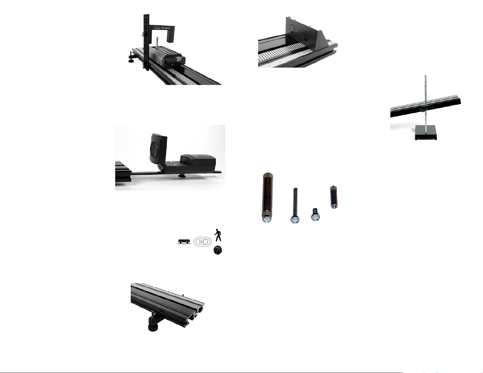
Photogate Bracket
Photogate Brackets are attached to
the side of the track. With the nut
loosely on the T-handled bolt, slide
the nut into the side channel of the
track. Attach the photogate using the
supplied wing bolt in the long slot.
Adjust the gate height so the beam
intercepts the desired portion of the
target.
Motion Detector Bracket
Although we expect that the motion encoder will be used most often to record
motion data, it is also possible to use an ultrasonic Motion Detector.
Any Vernier Motion Detector with a hinged head can be attached to the supplied
Motion Detector Bracket. The Motion
Detector Bracket has a pin to locate
the Motion Detector on the bracket.
There is a knob, nut, and bolt to
attach the bracket to the track
underside, and a threaded hole at the
end near the pin. To assemble, place
the Motion Detector with the back
end over the pin of the bracket. Insert
the screw through the slot into the
threaded insert on the detector with
the hinge toward the track, and tighten. Insert the bracket into the slot in the
underside of the track as shown in the photo. When the Motion Detector is not
attached to the bracket, its mounting screw can be stored in the threaded hole near
the pin.
Newer Vernier Motion Detectors (green or black case with
adjustable sensitivity) can be placed so that the sensor is 15 cm
from the end of the track. The carts can then be detected
properly all the way to the end. The track mode is appropriate
for the dynamics system.
Adjustable Leveling Feet
The Adjustable Leveling Feet slide into the
end of the track, with the nut in the center
slot of the track underside. Adjust the height
as desired. Install the feet before attaching
the Motion Detector Bracket.
Adjustable End Stop
The Adjustable End Stop slides into the end of
the track. Adjust the position as desired. Insert
magnets in the End Stop if desired.
Rod Clamp
The Rod Clamp is used to support the track with a
user-supplied ring stand. Insert the Rod Clamp nut
into the side of the track. Adjust the height as
desired.
Mounting Hardware
The supplied mounting hardware is used to
attach devices to the cart, such as a force
sensor, accelerometer, or mass. To attach a
Wireless Dynamics Sensor System (WDSS)
use the hardware supplied with that device.
The hex-head bolts may be attached to any
point along the slots in the cart, but the head
must be inserted in the flare region of the
slots. Tighten the threaded barrels on the
bolts.
5
6
Page 4

The Additional Mass (MASS)
ost
The 500 g mass is used to double the mass of the cart.
1. Insert the hex head of the #10-32 x 1-3/4″ screw into either of the side slots on the
cart from the flared end.
2. Fit the mass over the screw and position the mass and screw as required on the
cart.
3. Screw the small barrel onto the projecting end of the #10-32 x 1-3/4″ screw and
tighten to secure the mass.
Magnetic Bumpers
The Vernier dynamics carts are supplied with
magnets and hook-and-pile tabs. You may choose to
install either or both on your carts. Since the magnets
may interfere with certain experiments using force
sensors on the carts, only install the magnets if you
need them.
The magnets are useful in studying collisions with
the magnets positioned so that they are the same
polarity on both sides and on both carts. This way the
carts will repel one another, and you can arrange a collision in which the carts never
actually touch. The collision will be very nearly elastic, unlike a collision using a
spring or any kind of contact.
To install magnets so that carts will repel one another, as well as the Adjustable End
Stop, use the following procedure.
1. Remove the teardrop from the cart end or the End Stop.
2. Insert the silver magnet (supplied with the cart) into the teardrop, oriented so that
the outside of the teardrop will attract the south-pointing end of a compass needle.
3. Insert a foam plug (supplied with the cart) into the teardrop.
4. Reinsert the tear drop into the cart end or the end stop, and fasten the screw.
If you like, test by holding the compass near the cart or stop, in the same position as
an approaching cart, and verify that the south-pointing end of the compass is
attracted to the cart.
Carts come with magnets, foam plugs, teardrop inserts, and a hex key to remove and
replace the screw holding the teardrop to the cart end. A magnetic compass is not
included.
The magnets can be removed at any time by reversing this process. Store the
magnets away from computers.
To study totally inelastic collisions, place hook-and-pile tabs on top of the
teardrop-shaped plugs. Looking at the end of the cart, place a hook pad on the
left-hand plug, and a pile tab on the right-hand side. Center the pad on the round part
of the plug. This way any cart with hook-and-pile tabs will stick to any other.
Hook-and-pile equipped carts will stick together, creating a totally inelastic collision.
One cart includes a spring-loaded plunger for collisions. To use the plunger,
simultaneously press the horizontal button above the plunger and press the plunger
in until it locks. To release, press on the pin from the top of the cart. The plunger
force can be adjusted. To adjust the plunger release force, rotate the plunger while it
is extended.
Both the plunger and encoder carts have a mass of 500 g. Adding accessories will
change the mass.
Use of Additional Accessories and Sensors with the Encoder
System
The following examples show various sensors attached to a Vernier dynamics cart.
Sensors are not included with the Vernier Motion Encoder System.
Attach the Dual-Range Force Sensor (DFS)
1. Insert the hex head of the screw on the bottom of the post into the center slot of
the cart at the flare. The flats of the hex head should be parallel to the slot and the
washer should be above the slot to avoid marring the cart with the metal post.
2. Slide the post to the desired position on the cart and lightly tighten in place with
the knurled end of the post.
3. Place the DFS on the cart with the post through its central hole. Reposition the
post if necessary, and tighten. Tighten the plastic screw on the end of the sensor to
secure the DFS in place.
P
Plastic screw
7
8
Page 5

The Low-g Accelerometer (LGA)
The LGA is attached to one of the side slots of the cart using the #10-32 x 3/8″ hex
head screw and the small threaded barrel. The LGA is attached on one side only to
maintain the correct orientation of the sensor.
1. Insert the #10-32 x 3/8″ hex head screw into one of the mounting holes of the
LGA from the bottom and screw on the barrel a few turns, leaving at least half of
the screw threads exposed for fitting into the slot.
2. Use the arrow printed on the sensor to decide which of the cart side slots to use so
that the sensor is oriented in the desired direction.
3. Slide the head of the screw into the chosen slot from the flared end, position the
sensor as required, and tighten the small barrel to secure it to the cart.
DFS and LGA in Combination
The DFS (Dual-Range Force Sensor) and LGA (Low-g Accelerometer) can be
combined using the same procedures.
As long as the DFS is positioned so that the attachment to be used is facing in the
required direction, the order of attachment is not critical.
MASS and DFS
Attach the DFS first, since the plastic screw on the DFS becomes inaccessible when
the MASS is attached.
The DFS must be attached at the opposite end of the cart from the slot flares if you
want to be able to remove the mass without removing the DFS.
MASS and LGA
For this combination, the order of attachment is not critical.
MASS, DFS, and LGA
This is a similar case to the MASS and DFS, where the DFS must be attached first.
There is sufficient room on the new MASS bolt to piggyback the LGA on top of the
mass before attaching the small barrel.
9
10
Page 6

Wireless Dynamics Sensor System
For connection to a Vernier dynamics cart use a 5/8" × 10-24 binding barrel and a
hex-head bolt (1" × 10-24). First place the bolt head in the middle slot of the top of
the Vernier dynamics cart. Then lower the WDSS on top of the cart and insert the
binding barrel in the large hole of the WDSS. The bolt threads into the binding
barrel. Tighten the binding barrel. The process is shown in the series of photos
below:
General Hints for Vernier Motion Encoder System
Do not install the magnets unless you know you want to use them. They will
interfere if you perform an experiment with a force sensor riding on the cart, since
the force sensor will then not read the total force acting on the cart.
The magnets can be hard to pull apart if they stick together before installation;
slide them across one another to separate.
The conventional arrangement for magnets is to have the cart ends attract the S
end of a compass needle. The key thing is that all magnets repel, so if you use the
opposite convention everywhere, no harm is done.
The magnets are designed for fairly gentle collisions. If the cart is moving too
quickly, the magnetic forces may cause the cart to jump off the track to the side. If
this happens, use a lower initial velocity for the cart.
Keep the track clean; if it is very dusty the carts will not roll smoothly.
Use lower speeds and lower inclines than you might initially choose; the physics
is the same and students will have more time to observe what is happening.
Attach the track feet, sliding at least one in about 30 cm before inserting the
Motion Detector Bracket.
Study the Motion Detector Bracket photo carefully and note that the bracket is
attached to the underside of the track. A common error is to attach the bracket to
the top slot on the track.
Some Dual Range Force Sensors come with a plastic bolt that is too long to allow
simultaneous attachment of the DFS with a MASS. If your bolt is long, use a wire
cutter to remove a few threads at a time.
Suggested Experiments with the Vernier Motion Encoder System
The Vernier Motion Encoder System can be used wherever a Motion Detector could
have been used with a cart and track. The encoder depends on the presence of the
track, so that only cart and track experiments can be performed.
Measure Cart Acceleration
The basic motion of a cart on a ramp can be studied. For example, perform
Experiment 3 from Physics with Vernier, “Cart on a Ramp.” Or, repeat Galileo’s
experiment of determining g using an object and a ramp. This is Experiment 4,
“Determining g on an Incline,” from Physics with Vernier.
Newton’s Second Law
Use a force sensor on the encoder cart to record both applied force and acceleration.
The two will be proportional.
Or, set up a half-Atwood machine with a hanging mass and a pulley at the track end
opposite the receiver. Measure the acceleration of the encoder cart as a function of
the hanging mass.
Measure Fan Cart Acceleration
Add a Cart Fan (order code: FAN-VDS) to observe the motion of a cart under
constant thrust.
Measure Cart Acceleration with Friction
Add a Friction Pad (order code: PAD-VDS) to the encoder cart and observe the
motion of the cart with varying frictional forces.
Momentum-Impulse
Add a force sensor and a Bumper-Launcher Kit (order code: BLK) to observe the
relationship between momentum and impulse. Find the impulse by integrating under
a force vs. time graph.
Conservation of Energy
Use two Vernier Motion Encoder Systems to observe a change in energy due to a
collision between two carts.
Conservation of Momentum
Use two Vernier Motion Encoder Systems to observe a change in momentum due to
a collision between two carts. Try different kinds of collision: elastic, inelastic,
totally inelastic.
Products Related to the Vernier Motion Encoder System
Vernier Dynamics System (order code: VDS)
Vernier Dynamics System is a low-friction black anodized 1.2 m track and optics
bench combination designed for kinematics, dynamics, and optics experiments. It
includes two carts.
Vernier Dynamics System with Long Track (order code: VDS-LONG)
The long version of the Vernier Dynamics System includes a 2.2 m track instead of
the 1.2 standard track.
Track (order code: TRACK)
The Combination 1.2 m Track/Optics Bench comes with the Encoder System Strip
installed.
Bumper Launcher Kit (order code: BLK)
The Bumper Launcher kit includes accessories to integrate the Dual-Range Force
Sensor (DFS-BTA) with the Vernier Dynamics System or Vernier Motion Encoder
System, allowing for many interesting experiments in momentum-impulse study.
11
12
Page 7

Dual-Range Force Sensor (order code: DFS-BTA)
The Dual-Range Force Sensor measures pushes and pulls up to 50 N.
Wireless Dynamics Sensor System (order code: WDSS)
The WDSS is a wireless force sensor and accelerometer.
Replacement Parts
Motion Encoder Receiver (order code: MEC-BTD)
The receiver attaches to the end of the track and connects to an interface, such as a
LabQuest 2.
Motion Encoder Cart (order code: CART-MEC)
This is the complete Motion Encoder Cart, with no assembly required.
Motion Encoder Track Strip (order code: METS)
The strip can be attached to an existing track without an encoder strip, or it can be
attached as a second strip for use with two encoder systems. For 1.2 m track.
Motion Encoder Track Strip - Long (order code: METS-LONG)
The strip can be attached to an existing track without an encoder strip, or it can be
attached as a second strip for use with two encoder systems. For 2.2 m track.
Motion Encoder Transmitter Parts (order code: MECT)
The transmitter assembly is used to upgrade an existing cart to a Motion Encoder
Cart.
Suggested Accessories
Optics Expansion Kit (order code: OEK). The
Vernier-Optics Expansion Kit extends the Vernier
Dynamics System or Vernier Motion Encoder System
for use in optics experiments.
Color Mixer (order code: CM-OEK). The Vernier
Color Mixer Kit consists of a three-color LED
illuminator with power supply, a lens, and a doublesided screen. Experiments in additive and subtractive
color mixing can be easily and conveniently carried
out using this kit. The intensity of the red, blue and
green LEDs can be smoothly controlled from the
light source.
Ultra Pulley (order code: SPA). The pulley can be attached to
the end of a track using the Pulley Bracket to make a halfAtwood machine.
Pulley Bracket (order code: PB-SPA). The pulley
bracket allows easy attachment of an Ultra Pulley to
the end of a Vernier track. Compatible with a
photogate bracket for measuring motion using the
pulley.
The Cart Friction Pad (order code: PAD-VDS) is a variable friction mechanism for
use with the Vernier Standard Cart, Plunger Cart, and Motion Encoder Cart. It can be
used on any flat surface or, for best results, with the Vernier Dynamics System or
Vernier Motion Encoder System to study the effects of friction.
The two-speed Dynamics Cart Fan (order code: FAN-VDS) magnetically attaches
to the Vernier Standard Cart, Plunger Cart, and Motion Encoder Cart. It can be used
on any flat surface or, for best results, with the Vernier Dynamics System or Vernier
Motion Encoder System to study motion, force, and momentum.
Warranty
Vernier warrants this product to be free from defects in materials and workmanship
for a period of five years from the date of shipment to the customer. This warranty
does not cover damage to the product caused by abuse or improper use.
Vernier Software & Technology
13979 S.W. Millikan Way Beaverton, OR 97005-2886
Toll Free (888) 837-6437 (503) 277-2299 FAX (503) 277-2440
info@vernier.com www.vernier.com
Revised 10/8/2014
Logger Pro, Logger Lite, Vernier LabQuest, Vernier LabPro, Go!
trademarks or registered trademarks in the United States.
All other marks not owned by us that appear herein are the property of their respective owners, who may or may not be
affiliated with, connected to, or sponsored by us.
Printed on recycled paper.
Link, Vernier EasyLink and other marks shown are our
13
14
 Loading...