

Page 1
LabPro
Technical Reference
Manual
Calculator-Based Laboratory, CBL, CBL 2 , and
Incorporated.
LabPro is a registered trademark of Vernier Software & Technology.
2000 Vernier Software & Technology. All rights are reserved.
This document is modified and reprod uced from CBL 2 Technic a l Reference 2000 Texas Instruments
TI-GRAPH LINK
are trademarks of Texas Instruments
Revision Date: 08/02/02
Page 2

Revision Date: 08/02/02
Incorporated, with permis s ion of the publisher.
Contents
ABOUT THIS MANUAL.............................................................................................................................5
INTRODUCTION.........................................................................................................................................5
PROGRAMMING LABPRO ......................................................................................................................6
PROGRAM STRUCTURE..........................................................................................................................6
NITIALIZATION
I
HANNEL ACTIVATION
C
............................................................................................................................................6
.................................................................................................................................7
DATA COLLECTION MODES..................................................................................................................7
Data Collection Mode Comparison Table
IMEBASE
T
ATA RETRIEVAL
D
....................................................................................................................................................9
.........................................................................................................................................9
.............................................................................................8
MISCELLANEOUS REFERENCE INFORMATION.............................................................................9
ABPRO SOFTWARE UPGRADES
L
RCHIVING IN LABPRO’S
A
YPICAL PROGRAM IMPLEMENTATIONS
T
...................................................................................................................9
FLASH M
EMORY
................................................................................................9
.....................................................................................................10
Analog Data Collection ........................................................................................................................10
Analog RT Data Collection...................................................................................................................12
Motion Detector Data Collection .........................................................................................................13
Monitoring Inputs During NRT ............................................................................................................13
Monitoring Inputs without Data Collection .........................................................................................13
Interrupting Data Collection ................................................................................................................13
Keeping Power on During Analog Data Collection .............................................................................14
Digital Data Collection ........................................................................................................................14
Digital Outputs .....................................................................................................................................18
OMPUTER PROGRAMMING
C
........................................................................................................................21
Basic communications ..........................................................................................................................21
Data Formats........................................................................................................................................21
Serial Port Communication Details......................................................................................................22
USB Communication Details................................................................................................................22
OMMUNICATIONS SPEED LIMITATIONS
C
ALCULATOR PROGRAMMING
C
....................................................................................................................24
.....................................................................................................23
Basic Communication...........................................................................................................................24
Retrieving Data.....................................................................................................................................25
Data Control.........................................................................................................................................26
Calculator Limitations..........................................................................................................................27
LABPRO COMMAND SUMMARY ........................................................................................................28
OMMAND
C
OMMAND
C
OMMAND
C
OMMAND
C
OMMAND
C
OMMAND
C
OMMAND
C
OMMAND
C
HANNEL SETUP
1C
ATA COLLECTION SETUP
3D
ONVERSION EQUATION SETUP (ANALOG
4C
ATA CONTROL
5D
YSTEM SETUP
6S
EQUEST SYSTEM STATUS
7R
EQUEST CHANNEL STATUS
8R
EQUEST CHANNEL DATA
9R
.................................................................................................................31
..................................................................................................35
..................................................................................................................41
...................................................................................................................44
..................................................................................................45
...............................................................................................47
..................................................................................................48
).........................................................................39
LabPro Technical Manual2
Page 3

Revision Date: 08/02/02
OMMAND
C
OMMAND
C
OMMAND
C
OMMAND
C
OMMAND
C
OMMAND
C
OMMAND
C
OMMAND
C
OMMAND
C
OMMAND
C
OMMAND
C
10 A
12 D
102 P
115 R
116 R
117 R
201 A
401 A
1998 S
1999 S
2001 D
DVANCED DATA REDUCTION
IGITAL DATA CAPTURE
ORT POWER CONTROL COMMAND
EQUEST SET-UP INFORMATION
EQUEST LONG SENSOR NAME
EQUEST SHORT SENSOR NAME
RCHIVE OPERATIONS COMMAND
NALOG OUTPUT SETUP
ET
OUND COMMAND
IRECT OUTPUT TO DIGITAL-OUT PORT
LED C
OMMAND
....................................................................................................70
........................................................................................................71
.......................................................................................49
................................................................................................51
................................................................................56
.....................................................................................57
......................................................................................61
.....................................................................................62
..................................................................................63
.................................................................................................63
.......................................................................72
LABPRO HARDWARE.............................................................................................................................73
ONNECTOR PINOUTS
C
ECHNICAL SPECIFICATIONS FOR LABPRO
T
................................................................................................................................73
..................................................................................................74
General Specifications..........................................................................................................................74
Analog Inputs........................................................................................................................................74
Analog Inputs (Cont.)............................................................................................................................75
Analog Output.......................................................................................................................................75
Digital I/O.............................................................................................................................................75
ABPRO SENSOR DETAILS
L
..........................................................................................................................76
Voltage Sensor......................................................................................................................................76
Auto-ID Sensors....................................................................................................................................76
Custom Sensors.....................................................................................................................................77
APPENDIX A: GLOSSARY........................................................................................................................1
APPENDIX B: BEEPS, LIGHTS AND ERRORS.....................................................................................1
EEP AND LIGHT SEQUENCES
B
RROR CODES
E
..............................................................................................................................................2
.......................................................................................................................1
APPENDIX C: DATAMATE SENSOR SETUP DEFAULT SETTINGS...............................................1
APPENDIX D: COMPUTER PROGRAMMING EXAMPLES..............................................................1
General Structure of a VB Program.......................................................................................................1
Example 1: Temperature Non-Realtime Data Collection.....................................................................1
Example 2: Temperature Realtime Data Collection.............................................................................1
Example 3: Distance and Velocity Non-Realtime Data Collection.......................................................2
Example 4: Digital Output.....................................................................................................................2
Example 5: Digital In Data Collection..................................................................................................3
Data and String Manipulation................................................................................................................3
Comm Object Settings.............................................................................................................................4
APPENDIX E: CALCULATOR PROGRAMMING EXAMPLES.........................................................1
Example 1: Temperature Non-Realtime Data Collection......................................................................1
Example 2: Temperature Realtime Data Collection..............................................................................1
Example 3: Distance and Velocity Non-Realtime Data Collection........................................................1
Example 4: Multiple Channels Non-Realtime Data Collection.............................................................2
Example 5: Conversion Equation Setup (Command 4)..........................................................................2
Example 6: Data Control Setup (Command 5).......................................................................................2
Example 7: Digital In Data Collection...................................................................................................3
Example 8: Digital Out...........................................................................................................................3
Example 9: LabPro LED Display...........................................................................................................3
Example 10: Playing Music on LabPro..................................................................................................3
LabPro Technical Manual 3
Page 4

Revision Date: 08/02/02
Example 11: Command 8 Program.........................................................................................................4
Example 12: Command 9 Program.........................................................................................................4
Example 13: Command 10 Program.......................................................................................................4
Example 14: Archive Program (Command 201)....................................................................................5
LabPro Technical Manual4
Page 5

Revision Date: 08/02/02
About This Manual
This technical reference is intended for LabPro users who want to write their own programs for LabPro
and computers or Texas Instruments graphing calculators. This document includes technical data such as
syntax for LabPro commands, sample programs, error codes, specifications for sensors and miscellaneous
other topics.
We have created and have available for download from our web site starter software for REALbasic
(Macintosh), Visual Basic 6 for Windows and LabView for Windows, Macintosh and Linux/X-Window.
Most people who use LabPro do not need to refer to this manual. Instructions for using LabPro with the
DataMate calculator program or app are given in
LabPro package. Instructions for using LabPro with the Logger Pro computer program are in the Logger
Pro manuals and help files. Again, this manual is only needed if you are writing your own programs.
LabPro can be used to collect data or to control digital or analog lines when connected to either computers
or Texas Instruments calculators. The commands sent to LabPro and the results returned from LabPro are
usually the same, no matter what kind of computer or TI calculator is used. In this manual we will use the
term “host” to refer to either calculator or computer used to control LabPro. In a few cases, the commands
are different on calculators, and we will use the term “calculator”.
Getting Started with LabPro
, which is included in
If you plan to use LabPro with Texas Instruments calculators, this manual assumes that you are somewhat
familiar with the calculator, and the use of
to the calculator. If you are not, we encourage you to look over
calculator manuals for this information.
If you plan to use LabPro with your own computer software, this manual assumes that you are somewhat
familiar with the computer, the programming environment, and how the serial or USB port of the computer
is controlled. If you are not, we encourage you to look over other hardware and software manuals for this
information.
TI-GRAPH LINK™
for transferring programs from a computer
TI-GRAPH LINK, TI Connects,
and
Introduction
LabPro is a small handheld computer dedicated to the task of data collection and control of output lines. It
contains a microprocessor that can communicate with a host calculator or computer. By using the
command set documented in this manual, the host (computer or calculator) can customize the parameters
of the data collection or control to suit specific applications.
LabPro contains different types of on-board memory; ROM and FLASH RAM. The ROM contains the
most fundamental functions that allow LabPro to begin operation and load its operating system. The
operating system is stored in the 8Mbits of FLASH memory. Having the operating system in FLASH
memory provides the flexibility of future upgrades and feature enhancements. The FLASH memory is also
used to store programs such as the DataMate calculator program. The FLASH memory has a user
accessible portion that may be used for long term data storage or other programs.
LabPro has no ON/OFF switch. Instead, it uses an on-board power controller. When the LabPro goes into
an IDLE state, it automatically enters a micro power mode. Any outside stimulus, such as activity on any
of the communication ports or a button press will cause LabPro to “wake up” and return to a normal power
state. When collecting data slowly, LabPro will power down unused elements in order to maintain a low
power state between sample points.
The LabPro has three methods for communicating with a host; through the GraphLink port at the bottom
of the device, through the RS-232 port or through the USB (version 1) port. Only one of these ports may
LabPro Technical Manual 5
Page 6

Revision Date: 08/02/02
be used at a time. The GraphLink port is used almost exclusively with a TI Graphing calculator while the
USB and RS-232 ports are used with a computer.
LabPro has six interface ports for data collection. The ports labeled CH1 through CH4 are used to collect
analog data from sensors such as temperature, pH, force etc. The ports labeled DIG/SONIC1 and
DIG/SONIC2 are used to collect digital data from such sensors as photogates, motion detectors, radiation
monitors, and rotary motion sensors. LabPro may also be used to control 8 digital output lines and one
analog output line (see connector information for pin assignments).
Programming LabPro
Programming of LabPro consists of sending a series of commands to configure the desired operation.
There are a few dozen commands to control LabPro and request its status. Within a program, different
commands are used to set up the number of active channels, rate of data collection, quantity of data
collected, and how data is to be processed. Since the command set is rather extensive, this manual will
detail some building blocks to illustrate how the commands are used within the context of a program.
Each command consists of a series of numbers that are sent to the LabPro. For example, the data rate for
data collection is set with a Command 3, like this:
3,1,1,0
If you are using a TI calculator to write the programs, you typically store the data in a list and then send it
to LabPro. If you are using a computer to control LabPro, you send these commands to LabPro using
either the serial or USB port. Refer to the Calculator Programming and Computer Programming sections
of this manual.
While error checking and command parsing are built into LabPro, it is preferred that the program use the
commands as defined. That is to say, do not terminate commands in midstream. Complete requests for
data by retrieving requested data prior to sending a new command. In general, attempts to keep a
synchronous command/response sequence intact will add to the reliability of the design.
Program Struct ure
Programs for data collection with LabPro usually follow this basic pattern:
•
Initialize LabPro
•
Activate Channels from which data is to be collected.
•
Define and Initiate data collection mode.
•
Retrieve data from LabPro.
Initialization
Initialization takes place whenever the data collection settings need to be changed. The command used to
search for an attached LabPro is Command 7 (status command). Besides indicating if a LabPro is attached,
it provides valuable information regarding current status of the attached LabPro unit. Upon launch of the
program it may be particularly important to search for LabPro by only using a Command 7. This is due to
the fact that there may be data in the buffer from a previous experiment that needs to be accessed prior to
reset and setup commands being sent.
LabPro Technical Manual6
Page 7

Revision Date: 08/02/02
In order to clear all settings, send a reset, 0 command. This command clears data collection RAM, channel
assignments and data collection modes that are currently assigned in LabPro. This is a good first step to
put LabPro into a known state before configuring the channels. However, this is not to say that a reset
should always be sent to LabPro. In fact, since reset clears previous data, it is important to send reset only
when you are sure the user is done with the current configuration and data.
Example:
7 //Ask for status from LabPro
Get response //Evaluate response
0 //Reset LabPro to prepare for channel activation etc.
Channel Activatio n
In order to collect data from LabPro, the program must activate one or more channels. The channel setup
commands (Command 1 and Command 12) provide a means by which the program configures LabPro to
collect data from certain ports. This part of the program is where the channels are activated, calibration
equations are loaded and post-processing options are set. Channel activation tells LabPro which ports are
active and how to collect data from that port. Calibration equations are used to convert the raw voltage
reading to units specific to the sensor connected to the port. Post processing options further process the
data prior to returning the information to the host.
Data Collection Modes
Once LabPro has been initialized and the channels have been activated, the data collection details must be
programmed. Data may be collected and returned in several different formats depending on the host.
However, there are two basic modes of data collection, real time (RT) and non-real time (NRT). These
terms are a little misleading in that data is always collected in real time. The modes differ in how data is
stored in and retrieved from LabPro.
In RT data collection, data is collected at regular intervals and available to the host on a point by point
basis. Data collection begins after LabPro has processed the command. Only the most recent point is
stored in LabPro. If the program does not ask for the data often enough, data could be lost. In this mode,
data collection is performed as part of the main processing loop. Therefore, other tasks and processing will
determine when an opportunity for data collection occurs. LabPro attempts to take data as close as
possible to the programmed time interval. The accurate time between samples is reported back for each
data point. This is usually within 100 ms of the requested time. LabPro continues taking data until the host
stops data collection or resets the unit. This mode is useful for relatively slow time-based data collection
where an unlimited number of data points is necessary; such as a scrolling strip chart recorder.
In NRT data collection, data is collected at regular intervals. Data collection is interrupt-driven to achieve
accurate sample periods. Using a wide variety of definable triggers, the program may control when data
collection begins. LabPro stores the data in internal RAM until the requested number of data points have
been collected. The unit will return the list of data only after receiving a ‘get request’ from the host. If the
host sends the “get request” before data collection is complete, LabPro will begin data transmission after
the last point is sampled. It is possible to monitor the data as it is being collected by using Command 8.
This feature could be used to give the user a real-time view of data being collected in a NRT mode. Due to
its flexibility, this is the most commonly used mode. A special case of the NRT mode is FastMode
sampling. It is designed for use when a single channel must be sampled very quickly. This mode is used
primarily when sampling sound with a microphone, or to approximate an oscilloscope. In general,
FastMode is identical to non-realtime sampling with the following exceptions:
•
The sampling is limited to a single analog channel.
•
The selected channel must not be in operation mode 5, 6, or 7.
LabPro Technical Manual 7
Page 8

Revision Date: 08/02/02
•
The communications with the host are turned off during sampling.
Note: In FastMode sampling, it is very important that the program not issue any commands until after
sampling has been completed. If LabPro receives any command, it will abort FastMode sampling with an
error in order to respond to the command.
Data Collection Mode Comparison Table
The table below shows some of the differences between the data collection modes.
Realtime Mode Non-Realtime Mode FastMode
Order of data ret ur ned
when doing the GETs
from the host
computer
(n = # of samples
taken)
Number of samples
limited?
Sample time limits
(approximate)
Number of channels
limited?
{ch1_1, ch2_1, …
deltatime_1}
{ch1_2, ch2_2, …
deltatime_2}
:
:
{ch1_n, ch2_n, …
deltatime_n}
Not limited by LabPro,
but may be limited by
the host computer
This is determ ined by
host communication
speed. Sample Time
> 0.002 second to
16000 seconds
Yes, only CH1-4 and
11, 12
≤
{ch1_1, ch1_2, …
ch1_n}
{ch2_1, ch2_2, …
ch2_n}
{ch3_1, ch3_2, …
ch3_n}
{ch4_1, ch4_2, …
ch4_n}
{time_1, ti m e_2, …
time_n}
Yes, limited by
available memory in
LabPro
Sample Time ≥ 1e-4
seconds to ≤ 16000
seconds
No Yes, only a single
Same as NonRealtime
Same as NonRealtime
Sample Time ≥2e-5
seconds to ≤ 1e-4
seconds
channel from CH1 to
CH4
Can use Triggering? Not by LabPro,
performed in host
software
Communication
maintained during
sampling?
Notes:
1. Checksums are not returned when in ASCII mode communication with a computer, but they are
returned when using binary data transfer.
2. In Non-Realtime Mode, any post-process data will follow the input data for the respective channel.
In addition to RT and NRT modes, there is a single point mode. Using Command 9, a single point of data
may be read from an active channel. No time is associated with this reading. This command is extremely
useful for monitoring inputs, checking status of channels, and for very long term collection that may be
statistical or have the time base controlled by the host.
Yes Yes No
Yes Yes, however, manual
triggering is not
available.
LabPro Technical Manual8
Page 9

Revision Date: 08/02/02
Timebase
Regardless of which type of data collection is used, the user must set the data collection rate based on the
available rates offered by LabPro. The range of possible times between readings is from 16,000 seconds to
-5
2 x 10
same time, the shortest sampling time is 2 x 10
The data collection mode used affects the sample times allowed with LabPro. In normal mode, a system
tick of 100µs is used to set the sample time. The sample time must be an integer multiple of 100µs. Many
programmer designers choose to limit them to a finite number of rates, such as 10K, 5K, 2.5K, 2K, 1K,
500, 250, 200, 100, 50, 25, 20, 10, 5, 2.5, 2,and 1. At rates slower than 1 sample per second, the 100µs
clock allows reasonable timing accuracy for any sample time requested.
In fast mode, a system tick of 400ns is used to set the sample rate. The sample time must be time period
multiplied by 400ns resulting in an integer value. Many programmers limit the choices to rates of:
50K, 33K, 25K, 20K, 10K
Refer to the LabPro Command Summary section for further details.
seconds for analog data collection with a single channel. With two analog channels read at the
-4
seconds.
Data Retrieval
Data may be retrieved from LabPro in a several different ways. The most common way to collect data is to
send a get request. This will cause LabPro to return the next point in RT mode or to return the collected
data in NRT mode. Command 9 will collect a single point outside active data collection. This is useful
when wanting to monitor or test a channel. Command 8 can be used to return the most recent data point
collected during an NRT mode. Commands 5 and 12 is used to select specific data to be returned from
memory.
Miscellaneous Reference Information
LabPro Software Upgrades
LabPro uses FLASH technology, which allows you to easily upgrade to new software without buying a new
LabPro. As new functionality becomes available, you can download the software from the Vernier web site
to your computer and upgrade your LabPro.
Check the Vernier website (
compatibility statements. Directions for downloading upgrades will be given on the web site.
http://www.vernier.com
Archiving in LabPro’s FLASH Memory
LabPro has 24KB of FLASH memory that can be used for several purposes. In addition to allowing
updates to the operating system and storing the DataMate and other calculator programs, the FLASH
memory serves as an archive space for other programs and data.
To preserve collected data so that it can be retrieved at a later time, data sets can be stored in the FLASH
archive. To distinguish between different stored data sets, each data set can be given a name.
) for upgrades, paying special attention to
The FLASH archive can also store calculator programs and applications. This provides a convenient
location for storing frequently used programs or as a temporary storage to create more available memory
LabPro Technical Manual 9
Page 10

Revision Date: 08/02/02
on the calculator.
•
Calculator user can use the DataMate program to Save, Load and Delete data sets in the FLASH
archive. This can be very useful for performing and retaining multiple experimental trials in the
field. Directions for using this feature are given in the
•
You can write a program to review the list of stored data sets and retrieve the desired one for
DataMate Guidebook
.
further analysis. (See the sample archive program.)
•
Calculator users can use the DATADIR program (available on the TI web site at
http://education.ti.com/calc
FLASH memory. Directions for using the DATADIR program are given in the
Guidebook
Command 201, in conjunction with the Link menu on the calculator, provides access to these FLASH
.
or the Vernier web site http://www.vernier.com/calc) to manage
DataMate
archive operations. For details about Command 201, see the LabPro Command Summary section.
Typical Program Implementations
Analog Data Collect i on
Analog data collection is the easiest to learn and will be introduced in the next two sections.
Here is pseudo-code for a very simple LabPro data-collection program. This program takes readings from
a Vernier Barometer sensor. It will take 50 readings, 0.25 seconds apart. The general pattern is that you
transfer lists of numbers (commands) to LabPro.
0
1,1,14,0,0,1
4,1,1,8.729,8.271
3,0.25,50,0,0,0,0,0,1
Get analog data
Get time data
We will go over the program one command at a time below:
The first command initializes the LabPro using a Command 0. (Remember that the first number in the
command is the command type.) This is good practice prior to setting up data collection or when changes
take place. This command clears data, channel assignments and data collection modes that are currently
assigned in LabPro. However, this is not to say that a reset should always be sent to LabPro. In fact, since
reset clears previous data, it is important to send reset only when you are sure the user is finished with the
current configuration and data.
The second command configures the channel for reading data. Command 1 tells LabPro a number of
things about how data is to be collected. The official syntax for this command, when used with sensors, is:
1, channel, operation, post-processing, delta, conversion
You may not require all these features and you will rarely use some of them. (Use zeros, or leave them out
so the default value is used.) Here are the commonly used parameters:
channel
= The input channel is specified with the second number in the list. For analog sensors, you
can use 1, 2, or 3, or 4 (for CH1, CH2, CH3, or CH4). For a motion detector you use 11 for a Motion
Detector connected to DIG/SONIC1 or 12 for DIG/SONIC2.
operation
= The third number in the list provides more specific information regarding the channel
setup. This includes input selection (each analog port has two inputs) and use of internal conversion
information. In this example, we use a 14 to indicate that for this port, LabPro should collect voltage
data from the 0 to 5 V input. Most of Vernier analog sensors use this input. Many of Vernier sensors
LabPro Technical Manual10
Page 11

Revision Date: 08/02/02
now support an Auto-ID feature. By using a 1 for operation in this command, LabPro will
automatically determine input configuration, conversion information as well as other sensor specific
information. If no sensor is found during an Auto-ID process, it defaults to the 0 to 5V input. Using 14
is a more manual example. It is more common to exploit the AutoID feature.
post-processing
= This option directs LabPro to process the collected data to calculate values such as
first and second derivatives. Sometimes it is desirable for the host to calculate these values instead of
LabPro. Here we use zero since it is not needed.
= not used often, use zero
delta
conversion
= The sixth number in the list is either 0 or 1. If it is a 1, the LabPro will use a user
programmed conversion equation to convert voltages to readings which correspond to a sensor like a
force sensor, pressure sensor, magnetic field sensor, etc. If it is 0, either an internal conversion or no
conversion equation will be used. You should use a 0 in this position if you are using an AutoID
sensor or want to read back raw voltage values. Use a 1 if you are using a Vernier analog sensor with a
DIN (5-pin) plug or other sensors that don't support AutoID.
Let's take a closer look at the second line of our sample program:
1,1,14,0,0,1
Command 1 used here sets up channel 1 to use a Vernier sensor and (since the 6th value is 1) to use a
conversion equation.
The third line of our sample program uses a Command 4. Command 4 is only used to set up the calibration
equation for an analog sensor, such as one of the Vernier probes with a DIN connector. With the proper
Command 4, LabPro will read correct values (newtons, degrees Celcius, % dissolved oxygen, etc). If you
are using an AutoID sensor, or you just want to read the raw voltage from an analog sensor, do not use a
Command 4. Skip this line. Another way of saying this is that if the sixth number in your Command 1 line
is zero, do not use the Command 4.
If an equation is to be used to convert voltages to other measurement units, Command 4 is used to load a
conversion equation to LabPro. Almost all Vernier probes use linear calibrations (1st order polynomial).
The calibration is specified by entering k0 (the y-intercept) and k1 (the slope). For this kind of calibration,
the form of the Command 4 line will always be:
channel number
4,
,1,1,k0,k1
In our sample program, the following line is used to load the conversion equation:
4,1,1,8.729,8.271
In this case, channel 1 is being used, with a intercept of 8.729 and a slope of 8.271. This is the proper
calibration for a Vernier Barometer, calibrated in atmospheres. Information on the proper Command 4 line
values for each Vernier sensor is included in the sensor documentation.
Command 3 controls the actual data collection. Here is Command 3 from the sample program we are
studying. It specifies taking readings every 0.25 seconds for 50 readings, and specifies that we should
record the time of each reading.
3,0.25,50,0,0,0,0,0,1
The syntax for this command is:
3, samptime, numsamp, trigtype, trigch, trigthres, prestore, extclock, rectime, filter, FastMode
LabPro Technical Manual 11
Page 12

Revision Date: 08/02/02
Many of these features may not be needed and left in their default state or set to zero. Here are the
commonly used parameters:
samptime
numsamp
= the time between samples (in seconds). The range is 0.00002 to 16000 seconds.
= the number of readings to be made. This can be any integer from 1 to 12,000. (Numsamp
= -1 puts LabPro into RT data collection mode as explained below.)
trigtype
= this specifies if the program should wait for a triggering event before starting the actual
data collection. “0” instructs LabPro to begin data collection immediately without waiting for a
trigger. “1” means wait for the Start/Stop button on Labpro to be pressed. Other numbers can be used
to specify triggering on a certain signal level. The default is 1, which you usually do not want, so you
should almost always have to put a zero here.
The last two commands of our sample program are used to retrieve data from LabPro.
Get Analog Data
Get Time Data
As the first four commands of our sample program are executed, LabPro will go about its business of
collecting the data. The program should at some point send a command to LabPro requesting the data. The
details of this are different depending on the computer or calculator being used. Each command will get a
complete list of data from LabPro. The analog sensor readings will be retrieved first and then the times. If
we had set rectime to 0 in Command 3, then we would not have had the times recorded, and we would
have used only one retrieve command.
Analog RT Data Collect i on
The discussion above is about non-realtime data collection. That is, it assumes that you want to have a
certain number of readings taken at specified intervals for later use by the host (e.g., making a graph).
There is another variation of data collection that is sometimes used. We call this RealTime (RT) data
collection. In this type of program, LabPro takes one reading, the computer retrieves the reading (and
usually does something with it, such as put a point on a graph), and then the program loops and repeats.
Here is pseudo-code for a second sample program, similar to the first, but with RT data collection:
0
1,1,14,0,0,1
4,1,1,1, 8.729,8.271
3,1,-1,0
Label A
Get value of I
Display I
Goto A
This program is the same as the previous sample through the first three lines. After that, the data collection
portion is very different. Here is what is going on:
3,1,-1,0
Label A
Get value of I
Display I
Goto A
This is ju st a label, so the pro gram can loop ba ck h ere.
Note t he Comma nd 3 no w ha s a -1 for the number of samp les. This will
tell LabPro to take one reading and continue on.
Get the one reading and store it in the variable I.
Display this read ing.
Loop back to Label A and repeat.
Note that in most real programs you need to provide a graceful way of breaking out of this loop.
LabPro Technical Manual12
Page 13

Revision Date: 08/02/02
This type of data collection works great for many programs where you just want to monitor the reading
from a sensor as you collect data and take action if it exceeds a certain specified value; for example, a
program that turns on a fan if a temperature gets too high.
Motion Detector Data Collection
Programs for using motion detectors (also known as ultrasonic rangers) are somewhat like programs for
using an analog sensor. When using motion detectors, LabPro has the ability to return velocity and
acceleration. Below is pseudo-code for a typical motion detector.
0
1,11,1,2
3,.05,50,0
Get distance data
Get velocity data
Get acceleration data
Get time data
The Command 1 line is changed to use channel 11 for DIG/SONIC1. The parameter following the channel
number sets the units of distance the motion detector should read. In this case, LabPro will AutoID the
motion detector and read distance in meters.
The next paramteter in the list assigns a post-processing setting of data. The value of 2 tells LabPro to
calculate both velocities and accelerations (1
st
and 2nd derivative of the raw data with respect to time.)
In the sample program we requested that the velocity and acceleration be reported. Whenever either
velocity or acceleration is reported, the time of data collection will also be reported. As a result, we need to
get back four lists of numbers from LabPro.
Get distance data
Get velocity data
Get acceleration data
Get time data
Monitoring Inputs During NRT
Command 8 retrieves the most recent sample at request time and returns the value to the host. The
limitation is each channel must be requested individually.
8,1 request data point from channel 1
Note Command 8 only works for channels 1,2,3,4,11,12 and only returns values in ASCII.
Monitoring Inputs without Data Collection
Command 9 allows the program to sample a single point from a channel. It returns the current value at
request time to the host computer. The limitation is each channel must be requested individually.
9,1 request data point from channel 1
Note Command 9 only works for channels 1,2,3,4,11,12 and only returns values in ASCII.
Interrupting Data Collection
While in general it is best that commands and responses are kept synchronous and not interrupted, there
are situations when the user will need to terminate data collection. Using a reset command may do this.
However, if a reset is sent, all data is lost and the setup is erased. To gracefully terminate data collection,
LabPro Technical Manual 13
Page 14

Revision Date: 08/02/02
send a Command 6:
6,0
This will terminate data collection while keeping intact the data buffer and the channel configuration.
Keeping Power on During Analog Data Collection
LabPro tries to minimize power consumption by turning power off to sensors when data is not being
collected. There are some subtle issues involved with reading signals from sensors such as Vernier pH,
Conductivity, Ion Selective Electrodes, Dissolved Oxygen, CO
power to be supplied for some time to stabilize before readings are accurate. The way to solve this
problem is to send a Command 102 as shown the sample below. This command can be sent right after the
channel is set up. Command 102 controls how many seconds prior to sampling that power is applied to the
sensor. The –1 operation tells LabPro to keep power applied to the sensor at all times.
102,-1
Note that if you do this battery life will be reduced.
, and Flow Rate. These sensors all require
2
Digital Data Collection
Digital data collection using photogates, radiation monitors, and rotary motion probes are handled very
differently from analog data. In all cases, Command 12 is also used for setup and to retrieve the data.
Experiments can be performed using analog, sonic and digital channels simultaneously, but will require
additional steps during their set up and data recovery phases.
Important Note:
operating system does not collect data unless this is done. This is a known limitation and it may be
eliminated in future operating system.
Currently, at least one analog channel must be active in order to collect digital data. The
Photogate Timing
Photogates operate a little differently than the analog channel since the event occurrences are not
predetermined in time. There are many different timing modes as well. In order to allow the greatest
flexibility, the operating system commands are implemented in a rather generic way. It is up to the
program to process the data as needed to report the desired timing.
Photogate operation is also unique in that the same command (12) is used to setup data collection as well
as request gathered data. Use Command 12 prior to data collection to set up the timing modes. Use
Command 12 during and/or after data collection to retrieve the requested data.
In general, you will need to follow this sequence:
Set up an analog channel (even if you will not use the data collected)
Set up timing mode using Command 12
Start data collection using Command 3
Data collection terminates either manually or automatically (time interval is up)
Retrieve data using Command 12 followed by a “get”
Process data for desired timing information
A word about Command 3 setup. In most of the timing modes (except counter mode) the sampling period
is not a concern unless analog data is really needed. In most cases, this will be set for an arbitrarily long
experiment that is terminated by the user.
LabPro handles multiple digital inputs as separate measurements. The user is allowed to set up a wide
variety of combinations to get the timing they desire. However, it is up to the host program to use the
LabPro Technical Manual14
Page 15

Revision Date: 08/02/02
timing data from each of the LabPro channels and calculate the desired result.
The continuous pulse mode (time gate is blocked) is used for several modes of timing. The following
examples detail some common timing tasks.
Timing how long a photogate connected to a DIG/SONIC port is blocked (Gate Timing)
This timing mode is used to time pulses through a single photogate. The times reported to the user
represent the duration of the photogate being blocked. LabPro may be used in two modes; pulse width or
continuous pulse width. The difference being that pulse width stops collection after a single value has been
collected. Since Logger Pro currently supports multiple pulses under gate mode, it might be more useful to
use the continuous pulse mode. The setup would be:
0 Clear all channels and reset the device
102,-1 Turn power on continuously. Not required, but a good idea.
1,1,14 Setup one dummy analog channel, if no other analog channels have been assigned
12,ch,3,1 Timing mode where ch is channel number 41 or 42 (DIG/SONIC1, DIG/SONIC2
respectively).
The 3 parameter refers to continuous pulse mode and 1 refers to active low pulse.
3,60,1000,0 Send trigger information for arbitrarily long experiment unless real analog data is being
collected. This example sets the experiment length for 1000 minutes (1000 readings,
each of 60 seconds).
The experiment will terminate after this 1000 minutes; however, we do not need to wait until the
experiment is over to retrieve data. The Command 12 is used to poll for and retrieve available data. The
program must poll LabPro to find the number of available data points that have been collected.
12,ch,0 Requests the number of available data
The number returned will corresponds to the number of available events. The program may use this
number to set up data retrieval as well as when to update data tables etc. LabPro reports two types of data,
the pulse width and the time at which the pulse ended relative to the beginning of the experiment. (Note
that the time the pulsed ended, not the time it started, is reported.) These times are reported back in units
of seconds.
12,ch,-1,n,
The program may either “poll and retrieve” only new data or retrieve the entire data set each time. When
the user clicks on stop, the program should terminate data collection with a Command 6.
6,0
Timing how long each of two photogates is blocked, independently (Gate Timing with 2 Gates)
As mentioned before, the ports operate independently of each other so that the times reported back are
relative to each port. Simply setup and retrieve data as mentioned above using both ch 41 and ch 42.
Requests the pulse width times beginning at event n and ending at event m.
m
For instance, if 10 data points were collected and only points 8 to 10 were needed this
would correspond to n=8 and m=10. If n and m are omitted, all events are returned.
0 Clear all channels and reset the device
102,-1 Turn power on continuously.
1,1,14 Set up one dummy analog channel, if no other analog channels have been assigned
12,41,3,1 Set continuous pulse mode for digital input 1
12,42,3,1 Set continuous pulse mode for digital input 2
3,60,1000,0 Send trigger information for arbitrarily long experiment unless real analog data is being
collected. This example sets the experiment length for 1000 minutes.
LabPro Technical Manual 15
Page 16
Revision Date: 08/02/02
Poll channel 1 for a new event. Once an event has occurred, poll for an event change on channel 2. Once
this event occurs, retrieve the latest pulse widths from both these channels.
12,41,0 poll until you get a change in return value, store this in a variable, e.g.,
12,42,0 After channel one event change is detected, poll channel two until you get a change in
return value, store this in a variable, e.g.,
12,41,-1,j,
12,42,-1,k,
Store these events and begin polling again until the user terminates the experiment.
Timing from the time of blocking of one photogate until the blocking of the second photogate (Pulse
Timing)
This may be done by requesting the times back rather than the pulse width for the photogates. Setup is the
same as that for time with two photogates as mentioned above. However, now the times of interest are
different. Polling is done in the same manner in that an event must occur on channel one prior to channel
2. However, now the time of interest is the time from edge to edge of the pulses. Using Gate Timing with
two gates as the model, data retrieval now changes to:
12,41,-1,j,
12,42,-1,k,
12,41,-2,j,
12,42,-2,k,
Calculate the time from the blocking of photogate one to photogate two as follows:
get pulse width from channel one
j
get pulse width from channel two
k
j
k
j
k
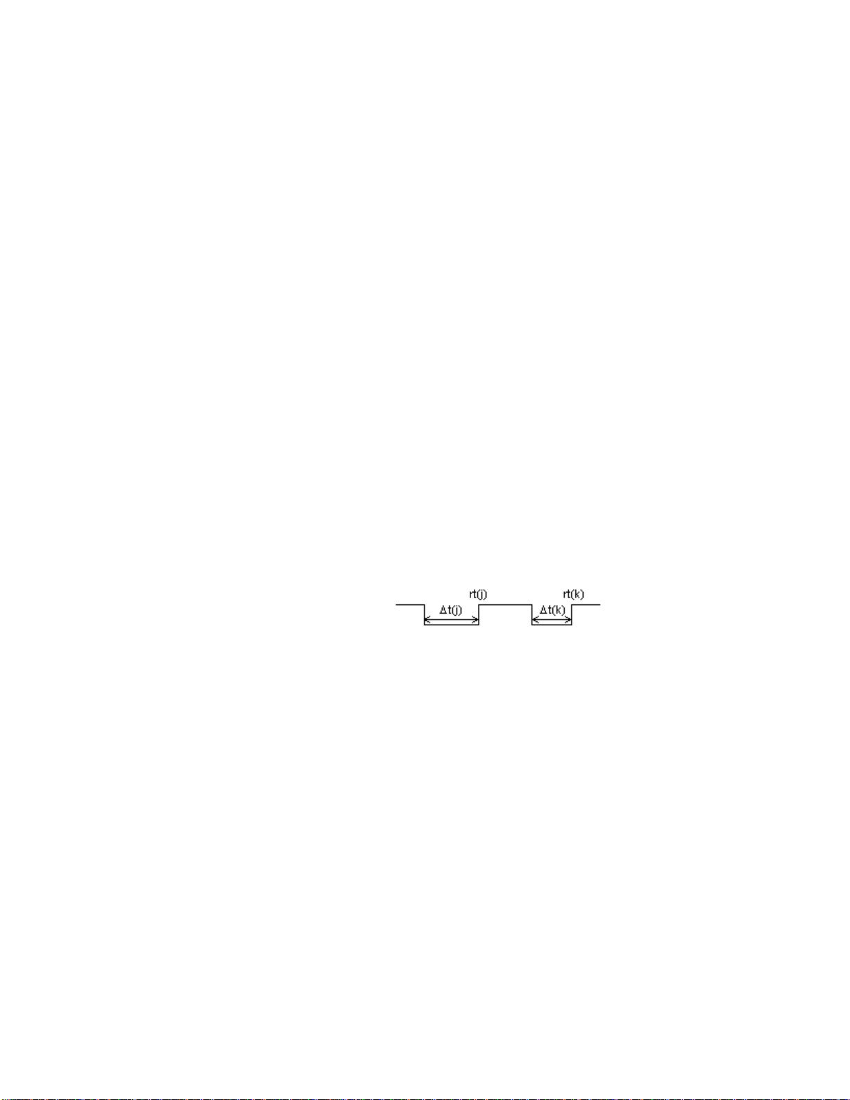
get pulse width from channel one. For equation below this is ∆t(j)
get pulse width from channel two. For equation below this is ∆t(k)
get pulse trailing edge time from channel one. For equation below this is rt(j)
get pulse trailing edge time from channel two. For equation below this is rt(k)
k
j
T = (rt(k) - ∆t(k))-(rt(j) – ∆t(j))
The user terminates the experiment.
Motion Timing
This is used to measure a continuous stream of pulses. For example, if an object with clear and opaque
sections (sometimes called a picket fence) is moved through a photogate. Many time measurements are
made. Each represents the time between successive blockings of the photogate. This uses a slightly
different mode than the previous examples, mode 4, for period measurement. For DIG/SONIC1, the setup
is as follows:
0 Clear all channels and reset the device
102,-1 Turn power on continuously
1,1,14 Set up one dummy analog channel, if no other analog channels have been assigned
12,41,4,1 Set period - continuous pulse mode for DIG/SONIC1
3,60,1000,0 Send trigger information for arbitrarily long experiment unless real analog data is being
collected. This example sets the experiment length for 1000 minutes.
Events retrieved are:
12,41,-1,n,m Requests the a subset of the data beginning at event n and ending at event m.
For instance, if 10 data points were collected and only points 8 to 10 were needed
LabPro Technical Manual16
Page 17

Revision Date: 08/02/02
this would correspond to n=8 and m=10. If n and m are omitted, all events are returned.
12,41,-2,n,m Requests the start times of each period measurement.
These two values are used to fill in the data table. Since the start times are referenced to the start of the
experiment, the value for the first event should be subtracted from the times to get the first event starting
at time t = 0.
Radiation Monitoring
Radiation counting is also set up using Command 12. It operates much like the photogate mode with the
exception that the data rate set in Command 3 is used to set the counting period.
The following is an example of how to set up radiation counting on DIG/SONIC1:
0 Clear all channels and reset the device
102,-1 Turn power on continuously
1,1,14 Set up one dummy analog channel, if no other analog channels have been assigned
12,41,5 Set count mode for digital input 1
3,30,2000,0 Send trigger information for arbitrarily long experiment unless real analog data is being
collected. This example sets the experiment length for 1000 minutes. The sample rate
determines the count information that is returned as the number of counts per 30
seconds.
Data is polled using:
12,41,0 returns number of available data points. This also is the number of sampling cycles that
have occurred since start.
12,41,-1,m,n returns data points starting with point m and ending at point n. Data is number of counts
that occurred during a sample period.
Rotary Motion Sensors
Reading data from a Vernier Software & Technology rotary motion sensor is also setup and monitored
using Command 12. LabPro reports the position of the sensor as a number in either low or high resolution.
The command to setup takes this form:
12, channel, 6, scale factor
where the scale factor should be 0 or 1 indicating whether you are in low or high resolution. If you use 0,
the resolution will be 360 counts per rotation of the sensor. If you use 1, the revolution will be four times
as many or 1440.
The following is an example of how to set up a rotary motion sensor on DIG/SONIC1.
0 Clear all channels and reset the device
102,-1 Turn power on continuously
1,1,14 Setup one dummy analog channel, if no other analog channels have been assigned
12,41,6,0 Set rotary motion mode for digital input 1 for low resolution measurements
3,30,2000,0 Send trigger information for arbitrarily long experiment unless real analog data is being
collected. This example sets the experiment length for 1000 minutes. The sample rate
determines the count information that is returned as the number of counts per 30
seconds.
Data is polled using:
12,41,0 returns number of available data points. This also is the number of sampling cycles that
have occurred since start.
LabPro Technical Manual 17
Page 18

Revision Date: 08/02/02
12,41,-1,m,n returns data points starting with point m and ending at point n. Data is position of the
rotary motion sensor, relative to its position when the data collection began.
Digital Outputs
The electrical characteristics of the digital outputs are:
♦
Voutput-high ≥3.7 V @ -400 uA
♦
Voutput-low ≤0.65 V @ 1.6 mA
Using Command 2001
This is the simplest way to set the status of the digital output lines. Just send the following command to
LabPro: 2001, X, where X is a number between 0 and 255, that matches the binary pattern you want on the
8 digital output lines. For example, sending 2001, 7 will set the first three digital output lines on
DIG/SONIC1 to high and all the other digital output lines to low.
Port
Bit Value
DIG/Sonic2
128 64 32 16 8 4 2 1
DIG/Sonic1
If you use a series of numbers after the 2001 in the command line, the data will be sent out at about 200-
µ
sec intervals.
Using the Digital Out put Buffer
A more complex method of controlling the digital output lines is to use the digital output buffer. This is
especially useful when you want a pattern of outputs to be repeated. Examples include, flashing LEDs or
stepper motors.
The digital output buffer (DOB) is a circular buffer that contains up to 32 elements. The output from the
buffer is 4-bits wide, and the outputs are CMOS (0-5V) compatible. The data in Command 1 is entered as
decimal representation of the digital value that is output. For example, 0=0000, 5=0101, and 15=1111. At
the beginning of each sample, a pointer into the digital output buffer is incremented and the next available
data is sent to the output lines.
The number of times that the DOB outputs the contents of the buffer depends on the number of data
elements defined in Command 1 and the number of samples defined in Command 3.
LabPro Technical Manual18
Page 19
Revision Date: 08/02/02
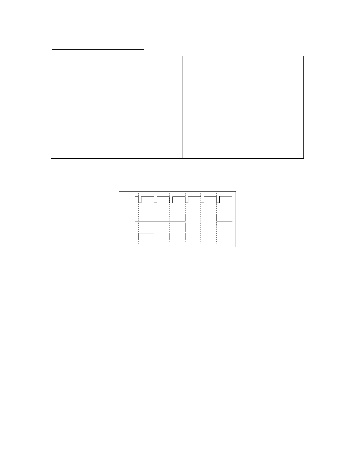
Digital Output B uf fer Example
Command 1 list is {1,31,5,1,2,3,4,5} where: Command 3 list is {3, 1, 100}
where:
1=Channel Setup.
31=DIG OUT.
5=Five data elements.
1=0001 (digital nibble).
2=0010 (digital nibble).
3=Sample and Trigger Setup.
1=One second sample time.
100=One hundred samples.
(Trigger T ype defaults to m anual
triggering.)
3=0011 (digital nibble).
4=0100 (digital nibble).
5=0101 (digital nibble).
The DOB outputs pulses that correspond to the five digital nibbles (1234512345...12345 etc.). This
sequence is repeated 20 times (100 samples/5 data elements) to the DIG OUT channel. The diagram below
shows a portion of this output for the first five data elements.
Sample
Clock
D3
D2
D1
D0
12345
1
Figure 1. Digital Output Example
Analog Outputs
The analog output is present on line 1 of CH4. Once the channel has been setup, the output is enabled
immediately regardless of data collection mode. It will remain active until the unit is reset or until it is
disabled using Command 401
When the output is activated using Command 401, the driving voltage may be monitored by reading Vin
on CH4.
The voltage out is limited to +/- 3 V and to +/- 100 mA. By changing the parameters you may change the
output value. A variety of waveforms are supported. Command 401 allows the program to set a waveform,
amplitude, offset and period and the analog output will generate the desired waveform. The official syntax
for this command is:
401, waveform, amplitude, offset, period
The current Lab Pro operating system revision understands the following parameter:
waveform
amplitude
offset
= DC voltage, ramp up, ramp down, triangle, sine
= the peak to peak voltage
= the voltage relative to ground
LabPro Technical Manual 19
Page 20

Revision Date: 08/02/02
= time (in milliseconds) to complete one cycle
period
The DC output voltage is set by the equation:
= 2.4mV*amplitude – 1.2mV*offset
V
out
The command
401,1,1024,1024,0
will output a 1.25V signal. To turn off the analog output:
401,0,0,0,0
When the analog output is off, the Vin line (pin 1) of CH4 line may be used as a ± 5 volt analog input.
Note that this is different from the other three analog input channels.
LabPro Technical Manual20
Page 21

Revision Date: 08/02/02
Computer Programming
Basic communications
Commands are sent using the following format:
s{
command number
where the command number is required followed by one or more parameters that may or may not be
required (see command reference section).
Data is returned either automatically or by requesting data by sending: the character "g".
Before you start programming, it is a healthy exercise to spend some time with a terminal program
(Hyperterm for Windows or Zterm for Mac are two examples) sending commands and receiving data.
Data Formats
ASCII Data
Numbers are returned as ASCII representation of 32-bit floating point numbers in the format of
sm.dddddEsee (sign mantissa_digit . digit digit digit digit digit E sign exponent exponent)
Hex Data
Binary mode is requested by the command {4,0, -1} but is only supported on the active analog and motion
channels. It reports the raw ADC output (i.e. calibration equations and derivatives are ignored). The data
format is 16 bits of ADC output that is zero filled, left justified according to the interfaces ADC resolution.
15 14 13 12 11 10 9 8 7 6 5 4 3 2 1 0
| |
|<------- LabPro 12 bit data ----------| 0 0 0 0|
| or |
|<---- CBL2 10 bit data ------ | 0 0 0 0 0 0|
| |
The data is transferred most significant byte first. No carriage return or line feed is transmitted.
In real time sampling mode, all active channels plus the 32-bit time counter are returned.
Ch1_MSB Ch1_LSB ... ChN_MSB ChN_LSB T_MSB T_B2 T_B1 T_LSB Chk
Where CH1_MSB indicates the most significant byte of data from the lowest number channel that is
active. After all the data has been transferred for a sample point, a checksum is included verifying the data
integrity (serial port only, does not apply to USB communications). The checksum is a single byte
computed by exclusive-ORing all bytes in the line and ones-complementing the result.
For example, assume you request a single data point with time. LabPro will transmit the following bit
pattern for a data value 8CH, a time of 00e0H and the checksum of 93H:
0000-1000 1100-0000 0000-0000
In non-real-time sampling mode, all N data points for the current channel are returned. Less than N data
points will be returned if windowing is turned on with Command 5. Each successive "Get" iterates through
MSB LSB
16-bit data 32-bit time ChkSum
, parameter 1,…, parameter n}
0000-0000 0000-0000 1110-0000 1101-0111
LabPro Technical Manual 21
Page 22

Revision Date: 08/02/02
the active channels, just as it does in the ASCII or calculator mode. For instance, with two channels active,
the following would be returned:
g (sent by host)
Pt1_Ch1_MSB Pt1_Ch1_LSB Pt2_Ch1_MSB Pt2_Ch1_LSB ... PtN_Ch1_MSB PtN_Ch1_LSB Chk
g (sent by host)
Pt1_Ch2_MSB Pt1_Ch2_LSB Pt2_Ch2_MSB Pt2_Ch2_LSB ... PtN_Ch2_MSB PtN_Ch2_LSB Chk
As in the real time mode, each case, the checksum is a single byte computed by exclusive-ORing all bytes
in the line and ones-complementing the result (serial port only, does not apply to USB communications).
After the checksum, transmission stops, i.e., no carriage return, linefeed or other stop character is sent
after the data.
Serial Port Communicati on Details
The serial port transmits commands and data requests in ASCII. Serial port setup is 38400,N,8,1. LabPro
will return command/response information in ASCII but has the option of returning collected data in either
ASCII or binary.
When communicating over the serial port, a carriage return character follows each command.
Since LabPro may be running from batteries, it may be in a low power state. In that case, if the host is
communicating over the serial port, the first byte will be missed. For safety, if the time since the last
communications is unknown, then the host should send an “s” followed by a carriage return to wake up the
LabPro. If it is not asleep, the “s” will be ignored. As an example, a status request would look like:
s<CR>
s{7}<CR>
While a setup sequence would look like:
s<CR>
s{0}<CR>
s{1,1,14}<CR>
s{3,.1,-1,0}<CR>
USB Communication Detail s
If the host is connected with USB, each time the program requests data, LabPro will send the data as soon
as the sampling occurs. If the program does not ask for the data often enough, data could be lost. If the
host is a computer connected through the serial port, LabPro automatically sends a continuous stream to
the host. This continues until the host stops data collection or resets the unit.
The LabPro enumerates with VID=08f7 and PID=0x0001.
There is 1 input bulk endpoint and 1 output bulk endpoint.
The USB packet size for bulk transfers is 64 bytes.
Transfers from LabPro to PC are always in multiples of 64 bytes.
The USB connection operates in much the same way as the serial port. It transmits commands and data
requests in ASCII. LabPro will return information in ASCII but has the option of returning collected data
in ASCII or binary. Some differences should be noted due to transport.
LabPro Technical Manual22
Page 23

Revision Date: 08/02/02
One significant difference is that trying to read from USB will not return 0 bytes of data, like an empty
serial port call. Instead, the call blocks until data is available from the LabPro. This occurs because LabPro
sends a NAK (Not Acknowledge) response until data is valid. The device driver will then wait, blocking on
the read, until the data is there. This means that the software read function will not return until the data is
ready. If this is an issue, the read request can be put in a separate thread so that the main thread can
continue to run. Third party drivers are available to create the abstraction of an input buffer similar to the
serial port operation.
The operating system in LabPro was written to make the USB interface as similar as possible to the RS232
serial interface. Getting data using USB works similar to getting data through the serial port, with some
subtle differences.
There is no checksum character for binary data, since the USB protocol already includes error detection.
Since the data is transmitted in multiples of 64 bytes, it is possible that there will be extraneous data in the
last 64-byte packet. The application software needs to know when to stop reading the buffer. In ASCII
mode, looking for a carriage return character can do this. In binary mode, it is only necessary to keep track
of the number of samples requested, and read the appropriate number of bytes.
In real time binary mode, each real-time sample is returned as 16 bits. The data is formatted as in the
RS232 design, then 0-padded up to 16 bytes. Real-time binary data is normally returned with 1 real-time
sample per USB packet. This allows roughly 1 sample/ms transfer rate, depending on loading conditions
and host controller design. If real-time sampling occurs faster that USB packets are delivered to the host,
there will be gaps in the real-time data. To allow deeper buffering of the sample data (and thus faster
sampling rates), there is an option to pack more than one sample per USB packet. The binary mode
command has an optional parameter to specify this packing. The command format is {4, 0, -1, X} where X
is the number of samples to place into one USB packet. X must be a value from 1 to 4. If no value is
specified, the default is 1. One consideration in applying this scheme is this: if USB packet delivery is
sufficiently delayed in this case, each delayed packet results in a gap that is larger than a single sample
time.
Communications Speed Limitations
LabPro may operate in two modes; real time (RT) and non-real time (NRT). In RT mode, LabPro returns
each sample as it is collected. However, the serial port or USB port have limitations on how fast they may
transfer data. The setup limitations depend on the data rate, the number of samples requested and the
length of the experiment. The primary factor for decision making is the number of active channels. From
that information, the determination of maximum rates etc. can be calculated.
When using LabPro in RT, the samples are not stored internally. Therefore, the max number of samples
and, consequently, the experiment length is limited by the software.
When using LabPro in RT mode over the serial port, the number of bytes per data point is 2*# of active
channels+4 (time bytes) + 1 (checksum) (see above information for details). This translates to
7,9,11,13,15,17 bytes per data point for 1 to six channels (four analog and two sonic) respectively.
Therefore, at a transmission rate of 38400, we can assume 10 bits/byte for a throughput of 3840
bytes/second. Using the timebase options above, we have the following theoretical limits imposed on real
time collect mode for serial port:
500 samples per second max. 1 channel active
250 samples per second max. 2 - 4 channels active
200 samples per second max. 4 - 6 channels active
LabPro Technical Manual 23
Page 24

Revision Date: 08/02/02
When using LabPro in RT mode over USB, the number of bytes transmitted back is always 16 (see above
information). For an unloaded USB bus (i.e. no other peripherals), we should have a limit of 1k samples
per second for RT mode for 1 to 6 channels active.
If you try to use RT at higher data rates, loss and corruption of data can occur. When the RT mode limit is
exceeded, the software must switch to utilize the NRT mode of LabPro. Data rate limitations change as
follows:
50K samples per second max. 1 channel active
5k samples per second max. 2 channels active
2.5k samples per second max. 3-4 channels active
2k samples per second max. 5 channels active
1k samples per second max. 6 channels active
Since the data is stored internally to LabPro prior to sending it to the host computer, the number of data
points being collected is limited to 12k samples/# of channels.
One implication of this is that the user may set up an experiment to take data from one channel at 1k
samples/second for 12 seconds. LabPro would not complete the data transfer for 18.25 seconds (12
seconds for the experiment + 6.25 seconds to data transfer over the serial port for 24000 bytes at 3840
bytes/second). Having such a delay may give the impression something is wrong. The software and the
user need to be aware of the times involved in such a situation.
Programming tips
Since the System Setup command (Command 6) must be processed while not disturbing data collection, it
is possible for additional data points to be transmitted after the Command 6 has been sent. These points
may be ignored but be aware that the receive buffer may not be empty immediately after sending this
command.
We have found that commands delimited by a carriage return character can be stacked in LabPro’s input
buffer. The input buffer can hold up to 300 characters. The benefit of stacking commands is that the
simple example
Calculator Programming
LabPro is designed to work with the TI-73, TI-82, TI-83 TI-83 Plus, TI-85, TI-86, TI-89, TI-92 and TI-92
Plus calculators. Programs are created on a TI calculator to set up specific LabPro operations, depending
on the experiment or other function that you want to perform. LabPro operations are controlled by
commands sent in the form of lists from a calculator. In the majority of cases, the data returned by LabPro
is also in the form of a list. As a rule, when a TI calculator is the host, LabPro is a passive communicator,
which must first receive a command list to provoke a response. Data is never automatically sent to the
calculator from LabPro.
Basic Communication
Below is a general example of communication between any TI calculator and LabPro:
command number
{
Send(listname)
Get(variable)
, parameter 1,…, parameter n}→listname
LabPro Technical Manual24
Page 25

Revision Date: 08/02/02
where the first line stores the
second line actively sends the list called listname to LabPro and the third line retrieves the requested data
from LabPro to variable on the calculator.
•
In the command list the
or may not be required. See the section titled LabPro Command Summary for details on the
commands and their parameters. We will use Command 7, the “Request System Status” command in
the examples to follow. This command has no parameters and is thus is sent as a single element list.
•
Any listname is acceptable when using “Send” to transfer the command list to LabPro. Refer to your
calculator guide book for the restrictions on list names and their syntax requirements. In the following
examples we will use the calculator list L6 for listname.
•
There are a number of types of variable that can be used in the “Get“ request. Most cases call for
using a calculator list. It is even common to use the same list for both listname and variable. For
clarity we will use the list called L1 to “Get“ data from LabPro to the calculator.
Only the TI-82 and TI-85 calculators need to store the command to a list in order to send it to
Note:
LabPro. All of the other calculators can omit the first step and simply use
{
command number
in the “Send” command.
Below is a working example which commands LabPro to generate and prepare to return a 17-element list
of status information and then places the requested information into the list called L1on the calculator. It is
shown in three ways to give the syntax for all of the supported calculators.
TI-73, TI-82, TI-83/83Plus, TI-86 TI-89, TI-92/92Plus TI-85
{7}→L6
Send(L6)…or simply: Send({7})
Get(L1)
, parameter 1,…,parameter n}
command number
command number
{7}→L6
Send L6…or simply:Send {7}
Get L1
and parameters to the calculator list called listname, the
is required followed by one or more parameters that may
{7}→L6
Outpt("CBLSEND",L6)
Input "CBLGET",L1
During the “Get”, the list L1 is deleted from the calculator and reformed by the data coming in from
LabPro. Regardless of the list’s length and contents prior to the “Get” request in our example, L1 should
look something like this:
{6.0112,0,0,888,0,0,0,0,0,0,0,0,0,1,0,0,0}
These steps can be executed from within a calculator program or line by line from the calculator home
screen. The TI-82 can only send commands from within a program. On the TI-73, TI-82 and TI-83/83Plus
calculators the lists called L1 and L6 are system-defined lists found on the keyboard or in the “List Names
Menu”. On the TI-85, TI-86, TI-89 and TI-92/92Plus calculators the lists called L1 and L6 are userdefined-lists which can be directly typed from the keyboard as the letter ‘L’ followed by the numbers ‘1’ or
‘6’. In either case, it is always best to initialize all variables prior to their use.
Retrieving Data
In the vast majority of cases, LabPro will be prepared to return data in calculator list format. However,
LabPro will return data in the format specified by the variable in the “Get(variable)” command. The
choices are: lists (as we used L1 above); list elements; real numbers; and in some cases strings or
categorical lists (TI-73 only). Below are examples and explanations of each of these (using the TI-83
syntax):
“Get“ request with a list element:
Send({7})
Get(L1(2))
In this case, only the second element of the list called L1is specified in the “Get” request. Therefore only
the second element of the list will be deleted and populated with the requested data. All other elements in
LabPro Technical Manual 25
Page 26

Revision Date: 08/02/02
L1 will remain as they were prior to the “Get“ request. Since LabPro was prepared to return a 17-element
status list on the next “Get“ request, and only a single list element was specified in that request, only the
first in the status list was returned as data. If L1 was {1,2,3,4,5} prior to the “Get“; after the “Get“ it would
be {1,6.0112,3,4,5}.
“Get“ request with a real number:
Send({7})
Get(A)
In this case real number variable A was specified in the “Get” request. Regardless of it’s contents prior to
the “Get“ request, the real number variable A will be erased and populated by the first value in the
commanded data. In this case A would be: 6.0112, the first element of the 17-element list requested by the
status command.
“Get“ request with a string or categorical list
:
When using some of the specialized archive commands (see section titled Archive Operation Commands)
it is possible to retrieve text directly from LabPro FLASH memory. There is a 20-character limit to the
length of each string and not all characters are supported. The format of this text depends on the data type
specified in the “Get” request. See below for details on individual calculator types.
For the TI-83/83Plus, TI-85 and TI-86:
•
If the data type specified is a string, LabPro will return a 20-character name of item.
•
If the data type specified is a list , LabPro will return a 20-element list, each element representing an
ASCII character code in the text string.
For the TI-73:
•
If the data type specified is a categorical list, LabPro will return 4 elements of 5 characters each.
Concatenate these 4 elements to form the complete text string.
•
If the data type specified is a list , LabPro will return a 20-element list, each element representing an
ASCII character code in the text string.
For the TI-89, TI92/92Plus:
•
The only allowable data type is a list. LabPro will return a 20-element list, each element representing
an ASCII character code in the text string.
Data Control
LabPro accepts over 20 different commands, each with a variety of parameters. Some of these, such as
Command 0 and Command 102, are used for experimental setup, power control or other administrative
purposes and do not generate data in response. While others, such as Command 7 and Command 201, will
generate data and prepare the LabPro to respond only to the next “Get” request. Data gathered from
experiments will remain in the LabPro data buffer, available for multiple retrieval, until the buffer is
cleared either by a loss of power or a command of type 0, 1 or 3. Be aware that pressing the Quick Setup
button will also clear the data buffer and reset any existing LabPro setup. If there is data in the buffer that
has been gathered from an experiment, successive “Get” requests will retrieve the data in an orderly
fashion. Each successive "Get" iterates through the active channel and time data, beginning with the lowest
active channel.
For Example:
CH1a, CH1b, CH1c, CH2a, CH2b,…,CHnc, Record Time, CH1a,…etc.
(Channel 1 is assumed to be the lowest active channel, a is raw data, b is d/dt, and c is d
2
/dt2 )
Refer to Command 5 for further information on data control.
LabPro Technical Manual26
Page 27

Revision Date: 08/02/02
Calculator Lim i tations
Calculator memory is an important factor to consider when collecting data with LabPro. Even though
LabPro can store up to 12,000 points, if a calculator has insufficient memory when using a “Get” request,
no data will be retrieved. Each element of a list, and therefore each data value takes up about 10 Bytes of
calculator memory (regardless of the calculator) and calculator programs also occupy memory. Each
calculator supported by LabPro has unique limitations on memory availability for program and data
storage and other limitations that may need to be considered while programming for LabPro. The table
below highlights some calculator features.
User available
memory (in
Calculator
TI-73 25 K No limit* 999* 2500
TI-82 28 K 6 99 594
TI-83 27 K No limit* 999* 2700
TI-83 Plus 24 K No limit* 999* 2400
TI-85 28 K No limit* 2800* 2800
TI-86 96 K No limit* 6000* 9600
TI-89 188 K No limit* No limit* 18800
TI-92 68 K No limit* No limit* 6800
TI-92 Plus 188 K No limit* No limit* 18800
Bytes) # of available lists
*Number will vary depending on available memory.
**These numbers are approximate, are based on a free memory, using 10 Byte/data point standard. The
TI-82 is limited to 6 lists of 99 points/list.
Maximum list
length
Maximum # of
data points**
LabPro Technical Manual 27
Page 28

LabPro Command Summary
The table below lists the commands you can use in writing programs for LabPro.
Command
Number Command Description
Revision Date: 08/02/02
0 Reset:
1 Channel Setup:
3 Data Collection Setup:
4 Conversion Equation Setup (Analog):
5 Data Control:
6 System Setup:
7 Request System Status:
8 Request Channel Status:
9 Request Channel Data:
10 Advanced Data Reduction:
Resets all channels to default conditions.
sets up a channel for data collection.
Sets up the collection parameters for an
experiment.
convert physical units measured by LabPro into a more useful
measurement unit such as newtons or °C.
Selects the type and range of data to be retri eved.
Turns sound on or off; sets an ID number for
LabPro; selects a filter to be applied to data.
Generates and prepares to ret ur n st atus
information.
Generates and prepares to ret ur n
sensor type, last valid data, and last valid data position f or t he
requested channel.
Generates and prepares to ret ur n one
data point before sampling starts. Used to verif y that set up i s
correct.
Sets up LabPro to process certai n
time-intensi ve algorithms instead of processing them in the
calculator.
Sets up parameters to
12 Digital Data Capture:
from the digit al input channel.
102 Port Power Control Command:
power-saving; or designat ed power up.
105 Baud Rate Selection:
106 Motion Detector Under sam pl e Rat e:
107 Oversampli ng Burst :
115 Request Set-up Information:
designated channel.
116 Request Long Sensor Name:
117 Request Short Sensor Nam e:
119 Request Alternate Calibrat ion:
the smart sensor.
Sets up the capture or measur em ent of data
Sets the power to always on;
Sets
Sets
Returns status information for the
Returns long sensor name.
Returns short sensor name.
Selects an alternate calibration for
Sets
LabPro Technical Manual28
Page 29

Revision Date: 08/02/02
201 Archive Operations Command: Allows the calculator to determine
the contents of LabPro’s
401 Analog Output Setup: Thi s command sets up parameters t o
control the analog output driver i n LabPr o.
1998 Set LED Command: Turns LEDs on and off on comm and.
1999 Sound Command: Specifies length and frequency of LabPro
sounds.
2001 Direct Output to Di gi tal-Out Port: Out put s data to the digital
output port.
Detailed information about each command is given below. Functionality is continually being added to each
command and the feature is denoted by a firmware version where it first appears.
FLASH
memory.
A table listing valid values follows the syntax of each command. Default values appear in
The syntax of each command is presented in terms of what is required and what is optional. Every
command must be enclosed in curly brackets, “{“ and “}”. The command # and the option parameters are
comma delimited.
Syntax: { command #, [option [,option…]] }
The command # represents the command to be issued to LabPro. The reset command has the simplest
syntax: s{0}.
[option] indicates an optional parameter. In many instances, using one optional parameter requires
additional optional parameters be specified. The channel setup command is a good example. It can take
one, two or five optional parameters.
boldface
type.
LabPro Technical Manual 29
Page 30

Revision Date: 08/02/02
Command 0 Reset LabPro
This command clears the data memory, error information, channel setup, and data collection information.
Only the RAM is reset; FLASH memory is not cleared.
Syntax: {0}
Return values: No information is returned.
Example: Clear LabPro
Computer Calculator
s{0}<CR> :Send({0})
LabPro Technical Manual30
Page 31

Revision Date: 08/02/02
Command 1 Channel Setup
This command sets up a channel for data collection.
Syntax:
Parameter List:
Channel – indicates channel on which this command operates. The possible values are
Operation – indicates the units of measure the channel should return.
{1,
channel[, operation[, post-proc, delta, equ]]
Channel number Description
0 All channels
1 – 4 Analog channels 1 through 4
11, 12 Sonic Channel 1, Sonic Channel 2
21, 22 Digital Input 1, Digital Input 2
31, 32 Digital Output 1, Digital Output 2
Operation Value Analog Channel (1 –4) Sonic Channel (11, 12)
0 Turn channel off Resets channel
1 Auto-ID the sensor
(default to 0-5V if no sensor found)
2 Voltage ±10V Meters – Returns distance and
3 Current ±10A
4 Measures resistance between
ground (pin-2) and the junction of
(pin-3) and V
V
ref
5 Period in seconds of signal on
±10V input line (CH 1 only)
6 Frequency in Hertz of signal on
±10V input line (CH 1 only)
7 Count of transitions on ±10V input
line (CH 1 only)
10 Temperature (Centigrade) from TI
Temperature or Stainless Steel
11 Temperature (Fahrenheit) from TI
Temperature or Stainless Steel
12 TI Light sensor Unused
14 Voltage, 0-5V Unused
in-low
(pin-6).
}
Meters – Returns distance and
∆
time (RT and NON-RT)
∆
time (RT and NON-RT)
Feet – Returns distance and ∆time
(RT and NON-RT)
Meters – Returns distance,
velocity, and ∆time (RT) or
distance and ∆time (NON-RT)
Feet – Returns distance, velocity,
and ∆time (RT) or distance and
∆
time (NON-RT)
Meters – Returns distance,
velocity, acceleration, ∆time (RT)
or distance and ∆time (NON-RT)
Feet – Returns distance, velocity,
acceleration, ∆time (RT) or
distance and ∆time (NON-RT)
Unused
Unused
Post-Proc – enables post processing to take place on data collected. Since data is not stored in RT mode,
no post processing is allowed.
Post-Proc Value Description
0 None (RT and NON-RT)
1 d/dt (NON-RT)
2 d/dt and d2/dt2 (NON-RT)
LabPro Technical Manual 31
Page 32

Revision Date: 08/02/02
Delta – used for internal debugging purposes and should always be set to zero (0).
Post-Proc Value Description
0 Not used but required as a place holder if EQU is specified
Equ – indicates whether or not a conversion equation is applied to the data before it is returned. If
Equ set to 1, Command 4 must be sent prior to data collection to specify the equation.
Equ Value Analog Channel (1 –4) Sonic Channel (11, 12)
0 No conversion equation applied No temperature compensation
1 Apply equation specified in
Command 4.
Return values: No information is returned.
Example 1: Clear all LabPro channels.
Computer Calculator
s{1,0}<CR> :Send({1,0})
Example 2: Clear Analog channel 3.
Computer Calculator
s{1,3,0}<CR> :Send({1,3,0})
Compensate for temperature as set
in Command 4.
Example 3: Set analog channel 2 to read 0 to 5V with all other channels off.
Computer Calculator
s{1,0}<CR> :Send({1,0})
s{1,2,14,0}<CR> :Send({1,2,14,0})
…collect the data…
get time and channel 2 data
Example 4: Set analog channel 1 to read voltages in the range of –10 to +10 Volts, analog channel 2 to
read current and calculate the first order derivative of current.
Computer Calculator
s{1,0}<CR> :Send({1,0})
s{1,1,2,0}<CR> :Send({1,1,2,0})
s{1,2,3,1}<CR> :Send({1,2,3,1})
…collect the data…
get time, channel 1data, channel 2 data and the
derivative column
Alternate Command 1 Syntax:
One variation on Command 1 is used for setting the output value on the Digital Output channels. LabPro
outputs one element for each sample. Between samples, the output returns to 0 unless the user has
commanded the power to remain on (using Command 102, -1).
LabPro Technical Manual32
Page 33

Revision Date: 08/02/02
0
1
2
3
T=
+
-
+
-
Syntax:
{1,
channel, operation, list of va lues
}
Channel Operation List of Values
31 = Digital Output 1
32 = Digital Output 2
0 = Clears the channel
1-32 = Count (number of data elements in list)
Values may be from 0 to 15.
The list of values must have one value for each count.
Example 5: Count down from 5. Note we set Channel 1 active. We don't have to retrieve the data.
Computer Calculator
s{102,-1}<CR> :Send({102,-1})
s{1,31,0}<CR> :Send({1,31,0})
s{1,31,6,5,4,3,2,1,0}<CR> :Send({1,31,6,5,4,3,2,1,0})
Set the period
Start counter
Measuring Period and Frequency
Period and frequency apply only to CH1 and only CH1 can be active if the operation is set to 5 (Period) or
6 (Frequency). Period and frequency are measured on Vin pin (pin 1) of CH1. Period and frequency
measurements always use the hardware threshold.
LabPro measures period and frequency by counting edges for 0.25 seconds, or by measuring the time
between the selected edges for one period—whichever is larger (see figure below). If a significant number
of edges are counted during the 0.25-second period, the count is used to compute both period and
frequency; otherwise, the period and frequency are computed from the time interval for one period.
Figure 2. Period and Frequency Measurement
Trigger Type
2
3
4
5
The crossover point between the two computations is about 600 Hz. Because there can be a one-count
Measuring Points
+ + (T=0 to 2)
- - (T=1 to 3)
+ +- (T=0 to 1)
+ -+ (T=1 to 2)
uncertainty during the 0.25-second period, the accuracy around 600 Hz is approximately ±4 Hz (about
0.7%). The resolution of the timer measuring the time between edges is 6.4 microseconds; therefore, the
percentage accuracy improves for frequencies above and below 600 Hz.
If LabPro is set up using Command 3 to make multiple measurements at a particular sample time, LabPro
waits for the sample time that you specified after it completes the current measurement. It then initiates the
next cycle of period/frequency measurement. The minimum sampling time for period and frequency is
0.25 seconds.
Note: Period and frequency measurements using Trigger Type 4 or 5 are only possible on non-repetitive
signals or on repetitive signals that are less then 600 Hz. This is because at 600 Hz, the edge counts will
prevail.
LabPro Technical Manual 33
Page 34

Revision Date: 08/02/02
The parameters shown in this table are used when measuring period or frequency.
Trigger Type Edge Polarity Used Hardware Threshold Used
0 Rising (+) Trigger Threshold paramet er
2–5 Specified by trigger t ype Trigger Threshold parameter
6 Not allowed (E.34 error).
Measuring Frequency
Assume a frequency measurement is requested on CH 1, and 20 measurements are desired at a .5 second
sample time.
The following commands would set up LabPro for this example:
{1,1,6}
{3,.5,20,2,0,1}
3 = Sample and Trigger setup command
.5 = Sample time of 0.5 seconds
20 = Number of samples to take
2 = Trigger from rising edge to rising edge for frequency
0 = Trigger channel not applicable
1 = Trigger at 1 Volt
Assume a ±10 Volt, 20 Hz sine wave is the input signal on pin 1. LabPro follows the sequence of steps
indicated below when the first trigger occurs (a trigger occurs every 0.05 seconds).
1. Trigger occurs on the rising edge.
2. Start counter and timer.
3. Stop timer at next rising edge.
4. Wait until 0.25 seconds has elapsed.
5. Stop counter (count should be about 5).
6. Count is less than 150 (or 600 Hz); therefore, frequency is computed from the time interval
for one period.
7. Wait for 0.5 seconds specified in Sample Time.
8. Wait for additional processing time to complete. (This time depends on what processing is
currently being performed and is typically about 0.25 additional seconds.)
9. Repeat steps 1 through 8 for nineteen more samples.
In this example, LabPro takes approximately 15 seconds to complete all the sampling.
LabPro Technical Manual34
Page 35

Revision Date: 08/02/02
Command 3 Data Collection Setup
This command sets up the data collection parameters for an experiment.
Syntax:
extclock, rectime, filter[, fastmode]]
Parameter List:
samptime – sets time between samples in seconds. The default sampling time is 0.5 second. The possible
numpoints – indicates the number of data points per input should be recorded. The possible values are 1 to
trigtype – indicates what events must occur on the Trigger Channel (trigchan) to start sampling.
{3,
samptime[, numpoints, trigtype, trigchan, trigthresh, pre-store,
}
values are 0.00002 to 16,000 seconds. Samptime may also be –1 if the previous sampling
needs to be repeated. Each probe has a minimum sample time, which is listed in the table
below:
Probe Type Minimum Sample Time
Analog probes
Sonic probes 8 milliseconds
Digital In/Out
12,287. A value of zero is invalid. Setting this value to –1 puts LabPro into real-time data
collection mode.
Pressing the START/STOP button will circumvent triggered data collection. The possible
values are
trigtype Value Trigger Type Exceptions
0 Immediate May not be used with frequency
1 Manual (default) May not be used with frequency
2 Rising edge / Rising edge May not be used with transition
3 Falling edge / Falling edge May not be used with transition
4 Rising edge / Falling edge May not be used with transition
5 Falling edge / Rising edge May not be used with transition
6 Single sample May not be used with frequency
100µsec per probe
20µsec per probe in FastMode
200µsec per channel
measurements or with period
measurements.
measurements, with period
measurements or with FASTMODE
sampling.
counting.
counting.
counting.
counting.
measurements, with period
measurements, with FASTMODE
sampling or with transition counting.
trigchan – indicates on which active channel the trigger conditions occur. Possible values are - zero (0)
for no triggering; one (1) for hardware triggering on analog channel 1; two (2), three (3) or
four (4) for software triggering on analog channels 2, 3 or 4; and 11 or 12 for DIG/SONIC1
or 2.
trigthresh – indicates the trigger threshold of the channel measured by the sensor attached to the trigger
channel. The type of the value used here is a float and must be within the measurable limits
of the channel.
LabPro Technical Manual 35
Page 36

Revision Date: 08/02/02
pre-store – indicates how much data (as a percentage of all measurements to be made) prior to the
triggering event should be stored. This value can be an integer between zero (0) and one
hundred (100). For example, if pre-store is set to 10 with 1000 total measurements to be
made, 100 data points made before the trigger event will be reported.
extclock – used for internal debugging purposes and should always be set to zero (0).
rectime – indicates the how time should be recorded for each data point. The possible values are zero
(0) which disables time recording; one (1) which time-stamps data relative to the start of data
collection; and two (2) which time-stamps data relative to the time of the previous sample. In
the last case, the data taken before the trigger event will have negative times.
filter – indicates what type of smoothing should be applied to the collected data. The possible values
are
Filter Value Description Used with collection mode
0 No filter realtime or non-realtime
1 Savitzsky-Golay 5-point filter non-realtime
2 Savitzsky-Golay 9-point filter non-realtime
3 Savitzsky-Golay 17-point filter non-realtime
4 Savitzsky-Golay 29-point filter non-realtime
5 Median Pruning 3-point filter non-realtime
6 Median Pruning 5-point filter non-realtime
7 Light Realtime tracking filter realtime
8 Medium Realtime tracking filter realtime
9 Heavy Realtime tracking filter realtime
fastmode – indicates whether or not data will be collected at the maximum sample rate allowed LabPro.
In FASTMODE, only one channel can be active, and it must be an analog channel. Sampling
can be as fast as 20
from 50,000 sample/second to 5,000 samples/second. The possible values are zero (0) for
normal operation and one (1) for FASTMODE operation.
µ
s/sample in this mode. FASTMODE is operational only for sample rates
Return values: No information is returned.
Example 1: Start reading samples and displaying them every 0.5 second.
Computer Calculator
s{3,0.5,-1}<CR> :Send({3,0.5,-1})
Example 2: Repeat last data collection.
Computer Calculator
s{3,-1}<CR> :Send({3,-1})
Example 3: Collect data every 10 seconds for 600 seconds and apply a Savitzsky-Golay 9-point filter.
Computer Calculator
s{3,10,61,0,0,0,0,0,0,2}<CR> :Send({3,10,61,0,0,0,0,0,0,2})
Triggering Details
Two types of triggering thresholds can be set in LabPro:
Hardware triggering is set to trigger on a specific voltage level established by the trigger
•
threshold parameter.
Software triggering is set to begin data collection on either the rising edge or falling edge of the
•
signal, depending on the trigger type and trigger threshold selected.
LabPro Technical Manual36
Page 37

Revision Date: 08/02/02
The THRESHOLD parameter specified in Command 3 can be used for two purposes:
•
If the operation in Command 1 is frequency, period, or count (operation = 5, 6, or 7 on Channel 1
only), then the threshold parameter in Command 3 sets a voltage level in LabPro hardware. The
signal on the Vin pin of CH 1 must pass through this voltage for LabPro to see the signal change
states.
•
If the operation in Command 1 is anything other than 5, 6, or 7, then the threshold parameter in
Command 3 specifies a trigger level and is measured in the units of the sensor selected.
When triggering, sampling does not start until the signal on the trigger channel (also specified in
Command 3) passes through this level once in the direction specified. This comparison of trigger level and
signal level occurs in software, so any level in the proper range can be selected. Also, either the Vin or Vin
Low pin (on any of the analog channels or the sonic channel) can be used as the trigger channel. LabPro
knows whether to use the Vin or Vin Low pin by looking at which operation was set up in Command 1.
If a conversion equation is enabled for the trigger channel, then the threshold specified in Command 3
should be a converted level. For example, if a pH probe is plugged into CH 2 with a conversion equation
loaded into LabPro and the trigger channel specified as CH 2, the threshold level should be entered as a pH
level in the range 0-14, not as a voltage in the range 0-5V.
Asynchronous / Synchronous Triggering versus Record Time
Actual triggering is asynchronous from the internal sampling clock when Trigger Type in Command 3 is
set to 1 or 6 (manual triggering). If sampling at very fast rates, the actual trigger may be slightly different
from the commanded trigger. The user should take this into account when calculating prestore and trigger
levels.
The actual sample time for the trigger point depends on whether or not prestore is selected in Command 3.
When prestore and relative record time are selected, the sample time for the trigger point will generally not
be identical to times around it. The time recorded for the trigger point will be the actual time between the
previous sampled point on the internal sampling clock interval and the asynchronous trigger event. The
sample taken after the trigger point will be at the specified sample time since the clock is reset each time
the trigger event occurs (pressing START/STOP or the hardware threshold trigger event).
When Trigger Type is set to 6 (Manual and Sample Trigger) in Command 3 and rectime = 1 or 2, the
recorded sample times are not the actual relative times when START/STOP is pressed. They are the same
times that would be returned during an NRT data collection. Thus, set the sample interval to 1 second and
rectime = 1 to get a list of sample numbers returned.
When no prestore is selected, the first sample time will be the trigger point. Its recorded time will not be
the internal sample clock time because LabPro is always sampling on the internal clock interval that you
selected and is storing points (if you selected prestore) until the trigger event occurs.
Example
Assume the following:
•
Input to CH1, set to measure ±10 Volts, is a 0.01 Hz sine wave.
•
Sample Time is set to 10 seconds and Number of Samples is set to collect 30 points.
•
Trigger Channel is set to 1.
•
Trigger Threshold is set to 1.0 and Trigger Type is set to 2 (trigger on rising edge).
LabPro Technical Manual 37
Page 38

Revision Date: 08/02/02
LabPro will collect and store a sample every 10 seconds. The recorded time for each sample will be 10
seconds. The trigger event (signal rising through 1.0 Volts) occurs 1.5 seconds after the previous sample,
so a sample collected at the trigger point is taken and stored with a recorded time of 1.5. The next sample
is taken 10 seconds after the trigger sample, not 8.5 seconds later as would have happened if the internal
sample clock had not been reset.
The Record Time returned (around the trigger point) will be the list: {...10,10,10,1.5,10,10,...}.
LabPro Technical Manual38
Page 39

Revision Date: 08/02/02
Command 4 Conversion Equation Setup (Analog)
This command sets up parameters to convert physical units measured by LabPro into a more useful
measurement unit such as newtons or °C.
Syntax: {4, channel[, equtype[, K0, K1]]}
Parameter List:
channel – indicates channel on which this command operates. The possible values are
Channel Description
0 All channels
1 – 4 Analog channels 1 through 4
11, 12 Sonic Channel 1, Sonic Channel 2
equtype – indicates what conversion equation is to be applied to the desired channel. Equation types
1 and 2 use a modified syntax. All equtype values except 13 apply only to analog channels 1
through 4. The possible values are:
equtype Equation Type Equation Restrictions
-1 Unary. Hex value
representing
5V/16bits.
1 Polynomial
2 Mixed Polynomial
3Power
4 Modified power
+ K1X + K2X2 + ... + KnX
K
0
X-m + ... + K-1X-1 + K0 +
K
-m
X + ... + KnX
K
1
(K1)
X
K
0
(X)
K
0K1
n
5 Logarithmic K0 + K1ln(X) X>0
6 Modified logarithmic K0 + K1ln(1/X) X>0
7 Exponential
8 Modified exponential
9 Geometric
10 Modified geometric
11 Reciprocal logarithmic
(K1X)
e
K
0
(K1/X)
e
K
0
(K1X)
X
K
0
(K1/X)
X
K
0
+ K1ln(K2X)]
[K
0
-1
12 Steinhart-Hart Model [K0 + K1 (ln 1000X) + K2(ln
1000X)
13 K0 in units of K
3…]1
1
K0 & K1 – Except when equtype =13, these are the coefficients for the equation defined by equtype
and are type float. When equtype=13, K0 is the ambient temperature in units defined by K1,
and K1 may have the following values:
K1 Temperature Units
0
°
Celsius
1
°
Fahrenheit
2
°
Celsius
3Kelvin
4Rankin
Data is returned in
hexadecimal format.
May only be used
with channel value
of 0.
n
1 ≤ N ≤ 9
0 ≤ N ≤ 4
0 ≤ M ≤ 4
M + N >0
X ≠ 0
X>0
K1>0
No restrictions other
than overflow.
X≠0
X≥0
X>0
K2X>0
X>0
Only applies to
channels 11 and 12.
LabPro Technical Manual 39
Page 40

Revision Date: 08/02/02
Return values: No information is returned.
Example 1: Compensate motion detector for air temperature of 29°C.
Computer Calculator Note
s{4,11,13,84.2,1}<CR>
s{4,11,13,29,2}<CR>
Example 2: Take 500 samples from Analog Channel 1 at 50,000/s in NRT mode and return the values in
hexadecimal values.
Computer Calculator Note
s{0}<CR>
s{1,14,1}<CR>
s{4,0,-1}<CR>
s{3,0.00002,500,0}<CR>
g<CR>
Example 3: Apply a logarithmic conversion equation to analog channel 2 data.
Computer Calculator
s{4,2,5,0,1}<CR> :Send({4,2,5,0,1})
:Send({4,11,13,84.2,1})
:Send({4,11,13,29,2})
:Send({4,11,13,84.2,1})
:Send({4,11,13,29,2})
For °Fahrenheit temps.
For °Celsius temps.
Reset the LabPro.
Enable 0 to +5V range input on Channel 1.
Set data to return in Hex
Start sampling
Get the samples from the LabPro
Alternate Command 4 Syntaxes:
When the polynomial conversion equation (equtype = 1) is used, the syntax for Command 4 is
{4, channel, 1, N, K0, . . .Kn}
When the mixed polynomial conversion equation (equtype = 2) is used, the syntax for Command 4 is
{4, channel, 2, M, N, Km, K
Example 3: Occasionally, data needs to be weighted by a polynomial function such as 4th order polynomial
as a crude frequency filter. This example demonstrates applying the polynomial function,
Y = -X^4 + 3.25X^2 – 2.25, to input data from analog channel 1.
Computer Calculator
s{4,1,1,4,-2.25,0,3.25,0,-1.0}<CR> :Send({4,1,1,4,-2.25,0,3.25,0,-1.0})
, . . .K0, . . .Kn }
m-1
LabPro Technical Manual40
Page 41

Revision Date: 08/02/02
Command 5 Data Control
This command selects the type of data to be retrieved, as well as the starting and ending data points to be
retrieved. This is the only command that requires “Get” statement to follow each Command 5 regardless of
the host. Sampling must be completed before sending Command 5 to control the data. Before sending
Command 5, do a Get statement to ensure that sampling is completed or send Command 7 to check the
status and verify that sampling is completed. Data End must be greater than or equal to Data Begin (unless
Data End = 0). Both DataBegin and DataEnd must be less than or equal to the number of samples reported
in the status command.
Syntax:
Parameter List:
channel – indicates which channel on which this command operates. The possible values are
Dataselect – indicates what conversion equation is to be applied to the desired channel. If Data Select =
databegin – indicates which data point (or row) the data block should start. Any integer value from zero
dataend – indicates which data point (or row) the data block should end at. Any integer value from
step – every nth point starting with first point in window. This first occurred in firmware 6.06227.
{5,
channel, dataselect, databegin, dataend, step
Channel number Description
-1 Recorded time
0 Lowest active channel
1 – 4 Analog channels 1 through 4
11, 12 Sonic Channel 1, Sonic Channel 2
21, 22 Digital Input 1, Digital Input 2
0, 1, or 2 and Command 3 Filter = 1-6, data will be filtered according to the filter selected in
Command 3. If Data Select = 3, 4,or 5; the filter setting in Command 3 will be ignored.
Dataselect may have the following values
dataselect Filter
0 Raw collected data (filtered)
1 d/dt (filtered)
2
3 Raw collected data (unfiltered)
4 d/dt (unfiltered)
5
to the last data point collected may be used. If this value is zero (0), the first data point
collected will be used to mark the beginning of the data. This parameter persists until LabPro
receives a Command 0 (Reset), Command 3 (Data Collection Setup), or another Command 5
(Data Control). Hence subsequent Get statements will return data with this databegin as the
starting point.
zero to the last data point collected may be used. If this value is zero (0), the last data point
collected will be used to mark the ending of the data. This parameter persists until LabPro
receives a Command 0 (Reset), Command 3 (Data Collection Setup), or another Command 5
(Data Control). Hence subsequent Get statements will return data with this dataend as the
ending point.
If your LabPro firmware is pre 6.06227, do not include this parameter. This parameter
persists until LabPro receives a Command 0 (Reset) or another Command 5 (Data Control).
Hence subsequent Get statements will return data every n points. A new Command 3 (Data
Collection Setup) will not reset this parameter as it does with the two former parameters.
2
/dt2 (filtered)
d
2
/dt2 (unfiltered)
d
}
Return values:
Example 1: Get all filtered, raw unfiltered data collected on analog channel 1. In the case of the calculator,
store the data in list L1. Then, look at the data in rows 1 through 7.
LabPro Technical Manual 41
No information i s r et ur ned until the next get command.
Page 42

Computer Calculator
s{5,1,3,0,0}<CR> :Send({5,1,3,0,0})
g<CR> :Get(L1)
s{5,1,3,1,7}<CR> :Send({5,1,3,1,7})
g<CR> :Get(L1)
Revision Date: 08/02/02
LabPro Technical Manual42
Page 43

Revision Date: 08/02/02
In a terminal session, the host-LabPro conversation appears as follows:
Host LabPro
s{0}
s{1,1,14,0}
s{3,0.02,11,0}
g { +2.31502E+00, +2.31868E+00, +2.32234E+00, +2.32479E+00, +2.32723E+00,
+2.21734E+00, +1.81319E+00, +1.48230E+00, +1.21368E+00, +9.92674E-01,
+8.11966E-01 }
s{5,1,3,0,0}
g { +2.31502E+00, +2.31868E+00, +2.32234E+00, +2.32479E+00, +2.32723E+00,
+2.21734E+00, +1.81319E+00, +1.48230E+00, +1.21368E+00, +9.92674E-01,
+8.11966E-01 }
s{5,1,3,1,7}
g { +2.31502E+00, +2.31868E+00, +2.32234E+00, +2.32479E+00, +2.32723E+00,
+2.21734E+00, +1.81319E+00 }
LabPro Technical Manual 43
Page 44

Revision Date: 08/02/02
Command 6 System Setup
This command can be used to turn sound on or off, set an ID number for LabPro, and select a filter to be
applied to data.
Syntax:
Parameter List:
syssetup – indicates which channel on which this command operates. The possible values are
parm – If syssetup has the value of 5, parm may be any floating point number between -1038 to +
Return values:
Example 1: Turn off LabPro sound.
Computer Calculator
S{6,3} :Send({6,3})
{6,
syssetup[, parm]
syssetup Description
0 Abort Sampling
1 * Undefined *
2 Abort Sampling
3 Turn sound off
4 Turn sound on
5 Sets an ID number for LabPro
6 Selects a filter to be applied to data
38
10
which sets the ID number for LabPro. This ID is used to identify a specific LabPro when
multiple units are linked together or attached to a single computer. If syssetup has the value
of 6, parm may have any value from zero (0) to six (6). Parm is the number of the filter to be
applied as specified by Command 3.
No information i s r eturned.
}
LabPro Technical Manual44
Page 45

Revision Date: 08/02/02
Command 7 Request System Status
This command returns LabPro’s 17 status registers.
Syntax: {7}
Return values: The following information is returned.
Register Description
softwareID Current software ID in format: X.MMmms where X=product code number,
MM=major ID number, mm=minor ID number, and s=step ID number.
error If non-zero, LabPro should be reset and the cause of the error corrected.
battery Battery status. Can return the following values:
0 Battery is OK for use
1 Battery is low during sampling
2 Battery is low all the time
8888 Constant value. If the correct list location is set to zero prior to requesting and getting
the list, this value can be used to ensure that the status message was received correctly.
Sample time Sample time that was commanded by the host during the last sample run.
trigger condition Triggering condition that was commanded by the host during the last sample run.
channel function Triggering channel that was commanded by the host during the last sample run.
channel post Post-processing setting that was commanded by the host during the last sample run.
channel filter Filter that was commanded by the host during the last sample run.
num samples Number of samples that was commanded by the host during the last sample run. If
sampling was aborted, this parameter reflects the actual number of samples taken.
record time This can have the following values:
0 No time was recorded in the last run
1 Absolute time was recorded in the last run
2 Relative time was recorded in the last run
temperature Temperature used for the temperature correction of the sonic data during the last run if
a sonic sensor was selected.
piezo flag This is the buzz/no-buzz value that was last commanded. Values are:
0 Sound is disabled (OFF)
1 Sound is enabled (ON)
system state The following values are used for the system state:
1 Idle
2Armed
3 Busy
4 Done
5Self-test
99 Initializing code
Add 16 to the value if the last mode was QuickSetup.
Add 32 to the value if the last data collected has not yet been retrieved.
datastart First point of data available for transmission to the host unless the host has sent
Command 5 to override this value.
dataend Last point of data available for transmission to the host unless the host has sent
Command 5 to override this value.
System ID The System ID that was set using Command 6.
Example 1: Request LabPro’s system status registers.
Computer Calculator
s{7} :Send({7})
:Get(L1)
LabPro Technical Manual 45
Page 46

Revision Date: 08/02/02
In a terminal session, the host-LabPro conversation appears as follows:
Host LabPro
s{0}
s{7} { +6.01120E+00, +0.00000E+00, +0.00000E+00, +8.88800E+03,
+0.00000E+00, +0.00000E+00, +0.00000E+00, +0.00000E+00, +0.00000E+00,
+0.00000E+00, +0.00000E+00, +0.00000E+00, +0.00000E+00, +1.00000E+00,
+0.00000E+00, +0.00000E+00, +0.00000E+00}
s{4,2,5,0,1}
s{7} { +6.01120E+00, +0.00000E+00, +0.00000E+00, +8.88800E+03,
+0.00000E+00, +0.00000E+00, +0.00000E+00, +0.00000E+00, +0.00000E+00,
+0.00000E+00, +0.00000E+00, +0.00000E+00, +0.00000E+00, +1.00000E+00,
+0.00000E+00, +0.00000E+00, +0.00000E+00}
s{3,10,61,0,0,0,0,0,2}
s{7} { +6.01120E+00, +3.10000E+01, +0.00000E+00, +8.88800E+03,
+1.00000E+01, +0.00000E+00, +0.00000E+00, +0.00000E+00, +0.00000E+00,
+6.10000E+01, +2.00000E+00, +0.00000E+00, +0.00000E+00, +1.00000E+00,
+0.00000E+00, +0.00000E+00, +0.00000E+00}
After the Command 3 was issued, the computer indicated an error by beeping 3 times. Command 7 is used
to see the error value, in this case, error 31. Looking the Error code appendix, error 31 means that
Command 3 was sent prior to performing any channel setups. However, the command was accepted and
LabPro can collect data every 10 seconds for 600 seconds and apply a Savitzsky-Golay 9-point filter.
LabPro Technical Manual46
Page 47

Revision Date: 08/02/02
Command 8 Request Channel Status
This command is used during data collection to read the operation or sensor type, the last valid data point
and the number of samples collected. Calculators must use the “Get” command to retreive this
information. Using this does not interfere with the active data collection.
Syntax:
Parameter List:
channel – indicates which channel on which this command operates. The possible values are
reqtype – determines whether the current sampled data is returned (reqtype = 0) or the data stored
Return values:
send a Get to retrieve these values.!!!Need to add info about –999.
operation
lastdata = last valid data read from sensor, if any. This is not applicable to CH1 with operations 5, 6, 7;
lastposn = last valid data position or the sample number where stored in the resulting list.
{8,
channel, reqtype
Channel number Description
1 – 4 Analog channels 1 through 4
11, 12 Sonic Channel 1, Sonic Channel 2
when channel was last setup (reqtype = 1.)
Reqtype value Description
0
1 previously sampled data is returned
Three values are returned –
= same operation used in Command 1
CH21 Digital In; or CH31 Digital Out.
}
current sampled data is returned
operation, lastdata
and
lastposn
. Calculators must
Example 1: Get the last sampled data collected. In the case of the calculator, store the data in list L1.
Computer Calculator
s{8,1,0}<CR> :Send({8,1,0})
g<CR> :Get(L1)
In a terminal session, the host-LabPro conversation appears as follows:
Host LabPro
s{1,14,1}
s{3,0.5,21,0}
s{8,1,0}
sent after the
th
data point
6
was collected
g { +2.14530E+00, +3.32112E-01, +2.30891E+00, +1.70085E+00, +1.10256E+00,
The values returned from the Command 8 line show that during data collection, point 6 was the last valid
measured row.
{ +0.00000E+00,
+2.24176E+00
+2.29060E+00, +1.29670E+00, +1.81441E+00, +2.18071E+00, +2.69841E-01,
+2.31502E+00, +1.81929E+00, +8.96215E-01, +2.26007E+00, +6.28816E-01,
+2.32723E+00 }
+2.24176E+00
, +2.44200E-01, +2.32357E+00, +2.02076E+00, +5.44567E-01,
, +6.00000E+00 }
LabPro Technical Manual 47
Page 48

Revision Date: 08/02/02
Command 9 Request Channel Data
This command requests one data point before sampling starts. Used to verify that setup is correct.
Syntax:
Parameter List:
channel – indicates the channel on which this command operates. The possible values are
mode – chooses between present setup or setup for previously collected run. This allows sensors to
Return values:
Get to retrieve these values.
curval
Example 1: Retest the analog channel 1 for a smart sensor. In the case of the calculator, store the data in
list L1.
Computer Calculator
s{9,1,0}<CR> :Send({9,1,0})
{9,
channel, mode
Channel number Description
1 – 4 Analog channels 1 through 4
11, 12 Sonic Channel 1, Sonic Channel 2
be disconnected after run is completed but still able to retrieve auto ID value.
Reqtype value Description
0
1 returns the stored AutoID value
one value is returned – current sensor value (curval). Calculators must send a
= immediate value of sensor which was setup in requested channel.
:Get(L1)
}
Re-tests the channel for AutoID value
In a terminal session, the host-LabPro conversation appears as follows:
Host LabPro
s{9,1,0} { +1.94383E+00 }
s{9,1,0} { +1.70452E+00 }
s{9,1,1} { +1.84005E+00 }
** Change to Barometer sensor **
s{9,1,0} { +2.19536E+00 }
s{9,1,0} { +2.19536E+00 }
s{9,1,0} { +2.19536E+00 }
LabPro Technical Manual48
Page 49

Revision Date: 08/02/02
Command 10 Advanced Data Reductio n
This command sets up LabPro to process certain time-intensive algorithms instead of processing them in
the host. This allows large data sets to be processed much more quickly.
Syntax:
Parameter List:
channel – indicates the channel on which this command operates. The possible values are
alg – algorithm to process..
{10,
channel, alg, P1, P2, P3
Channel number Description
1 – 4 Analog channels 1 through 4
Alg value Description
1 At the time this document was written, only the HeartBeat algorithm which
works as follows:
1. LabPro starts by finding the maximum and minimum points of the
data set. The lower threshold is set at P1 percent of the maximum
point, and the upper threshold is set at P2 percent of the minimum
point.
2. LabPro checks the difference between the maximum point and
minimum point against P3. If the difference is less than P3, the
algorithm is aborted and a 0.0 is returned. (This is the case where the
user expected the input data to have a certain variation but, for some
reason, the variation was not found.)
3. LabPro then finds the number of “rising edges” where the data in the
data set is increasing from below the upper threshold and the number
of “falling edges” where the data is decreasing to below the lower
threshold. The total number of rising edges and falling edges is
stored.
4. Next LabPro determines how many samples are between the first
edge and the last edge. The frequency is then determined as the
number of edges divided by the number of samples and is returned to
the host.
5. The user program is responsible for taking the result from LabPro
and dividing it by the sample time to get the true frequency in Hz.
}
P1 – value determines when data transitions from “high” to “low.” This value can be an
integer between zero (0) and one hundred (100) corresponding to 0 to 100 percent of the
lower threshold.
P2 – value determines when data transitions from “low” to “high.” This value can be an
integer between zero (0) and one hundred (100) corresponding to 0 to 100 percent of the
lower threshold. P2 must be greater than P1.
P3 – value determines the minimum difference in data between U pperThld and Lo werThld. This
value can be a real value in the units of the channel selected.
Return values:
LabPro Technical Manual 49
The value returned is result of t he algorit hm ’s calculation.
Page 50

Revision Date: 08/02/02
Example 1: Determine the frequency of a periodic signal on analog channel 1 from a 5000 point block of
data collected at 50 points per second. P1 is set to 10% of the lower threshold, P2 is set to 10% of upper
threshold and P3 is set to 0.5 volts.
Computer Calculator
s{1,1,14,0,0,0}<CR> :Send({1,1,14,0,0,0})
s{3,0.02,5000,0,0,0,0,0,0,0}<CR> :Send({3,0.02,5000,0,0,0,0,0,0,0})
s{10,1,1,10,20,0.05}<CR> :Send({10,1,1,10,20,0.05})
:Get(Rate)
Freq = Rate / SampleInterval = Rate / 0.02
LabPro Technical Manual50
Page 51

Revision Date: 08/02/02
Command 12 Digital Data Capture
This command sets up the capture of data from the digital input channels. The digital lines are electrically
“pulled” high so that the LabPro digital lines have a default state. Each DIG/SONIC port consists of four
digital lines. Command 12 reads a single line of each DIG/SONIC port. Figure 1 illustrates how the digital
lines are physical mapping. When Command 12 is used, the power generally stays on during sampling. As
a result, this mode tends to deplete the batteries very quickly. The number of data samples taken is limited
only by the avai l able m emory after memory i s reserved for the Comm and 1 channel s that are set up. LabPro has
about 12,000 available mem ory l ocations. If X channel s are setup and Y samp les are sel ected using Com m and
3, the number of samples on CH 41 is limited to (12,000 – X*Y)/3.You absolutely must have at least one
analog channel activated before sending the Command 3 to start sampling.
Syntax:{12, channel, mode[, P1[, P2]]}
Port
Bit Value
Parameter List:
channel – indicates which channel to work with. The possible values are
Channel number Description
41 DIG/SONIC Channel 1
42 DIG/SONIC Channel 2
mode – indicates what type of digital data collection to perform. The possible values are
mode Use
-2 Returns a list of numbers based on collection mode (>0), {see individual collection modes for
-1 Returns a list of numbers based on collection mode (>0), {see individual collection modes for
0 return number of points collected on next get statement; send after “getting” the analog
1 Sample Mode This mode is used when none of the other modes (below) are useful. In
2, 3 Measures pulse width of the data on the DIG/SONIC channel. This mode is used with a
4 Measures period of the data on the DIG/SONIC channel. This mode is used with a
DIG/Sonic2
128 64 32 16 8 4 2 1
definition of list} P1 and P2 are the data row indices, or Start and Stop
position for a block of data (see below).
definition of list} P1 and P2 are the data row indices, or Start and Stop
position for a block of data (see below).
channels
this mode, each time the data changes, it is recorded in LabPro. This
allows for any new digital probes to be used if the user is willing to write
the program to process the data. Mode –2 will return a list of times and
Mode –1 will return a list of final line states.
photogate to get very accurate measurement of the time a photogate is
blocked. Generally, this measurement is used to determine the speed of an
object (must know object’s length). Mode –2 will return a list of times and
Mode –1 will return a list of pulse widths based on the Direction indicated
by parameter P1 (see below).
photogate to get very accurate measurement of the times between when
the photogate becomes blocked. Generally, this measurement is used to
determine the speed of a wheel or a picket fence or the period of a
pendulum. Mode –2 will return a list of times and Mode –1 will return a
list of cycle widths.
DIG/Sonic1
LabPro Technical Manual 51
Page 52

Revision Date: 08/02/02
5 Counts transitions on the D0 input line of the Digital input port. This mode is used when the
frequency of a source with a TTL (or CMOS compatible) output must be
measured. Mode –1 will return a list of counts. Mode –2 is invalid in this
context.
6 Vernier Rotary Motion sensor. Generally this indicates the position of a wheel on the
sensor. Mode –1 will return the position of the rotary motion sensor,
scaled as indicated by P1 (see below). Mode –2 is invalid in this context.
P1 –During the setup of a mode this parameter can indicate the desired direction of the digital
signal or the scale factor of a rotary motion sensor. During the request of a block of data this
indicates which row is to be the start of the data block.
Direction Use (only with mode 2 or 3)
0
1 High Active Pulse width is the time between a low-high transition and the next
Scale Factor Use (only with mode 6)
0
1 High Resolution rotary motion (4 x Low Resolution).
Data Start Use (only with mode –2 or –1)
or integer N.
0
Low Active Pulse width is the time between a high-low transition and the next
low-high transition, or the time a photogate is un-blocked.
high-low transition, or the time a photogate is blocked.
Low Resolution rotary motion.
Start indicates which data point (or row) the data block should start at. Any integer
value from zero to the last data point collected may be used. If this
value is zero (0), the first data point collected will be used to mark
the beginning of the data.
P2 – Only used when requesting a block of data (mode of –2 or –1). This parameter indicates
which data point (or row) the data block should start at. Any integer value from zero to the
last data point collected may be used. If the default value of zero (0) is used, the last data
point collected will be used to mark the end of the data.
When used with mode 6, P2 is a Reset Inhibit (0 = count is reset to 0 on each new data
collection, 1 = count is not reset.) Valid first on firmware version 6.06228.
Return values: The value returned is r esult of t he algorit hm s calculation.
Example 1: Determine how many transitions have occurred on the D0 line.
Computer Calculator
s{12,41,0}<CR> :Send({12,41,0})
:Get(CNT)
Host LabPro
s{12,41,0} { +1.71000E+02 }
Example 2: Sample Digital Inputs
To illustrate digital input sampling, LabPro will be told to monitor both digital inputs for 10 seconds.
Host LabPro
s{0}<CR>
s{1,1,14,0}<CR>
s{12,41,1}<CR>
LabPro Technical Manual52
Page 53

Revision Date: 08/02/02
s{12,42,1}<CR>
s{3,10,2,0}<CR>
s{12,41,0}<CR> { +2.00000E+00 }
s{12,42,0}<CR> { +2.00000E+00 }
s{12,41,-2}<CR> { +2.40160E+00, +5.04500E+00, }
s{12,42,-2}<CR> { +3.80320E+00, +5.92310E+00, }
s{12,41,-1}<CR> { +0.00000E+00, +1.00000E+00, }
s{12,42,-1}<CR> { +0.00000E+00, +1.60000E+01, }
At each transition of the digital inputs, the absolute time and state of the inputs is reported (See Figure 3.)
This command can be run at the same time as analog sampling. The digital inputs are sampled 10,000
times/second. Each time a change in the input bits is found, the time and the new value are written to a
data buffer area. When the data buffer area overflows, data collection is halted and an error message is
sent.
Digital/Sonic
(D 1 , D 2)
Figure 3. Digital Input Measurement
The input lines can only have a value of zero or one. DIG/SONIC1, the return values will be 0 or 1.
DIG/SONIC2 being part of the upper 4-bits of the digital port will produce a 0 or 16. Each transition
stored takes two data point locations – one for final state and one for time.
Example 3: Pulse Measurement
To illustrate its use, both ports will be used to monitor the time each time the photogates are blocked by
the opaque bars on a Vernier Picket Fence.
Host LabPro
s{0}
s{7} { +6.01510E+00, +0.00000E+00, +0.00000E+00, +8.88800E+03, +0.00000E+00,
+0.00000E+00, +0.00000E+00, +0.00000E+00, +0.00000E+00, +0.00000E+00,
+0.00000E+00, +0.00000E+00, +0.00000E+00, +3.30000E+01, +0.00000E+00,
+0.00000E+00, +0.00000E+00}
s{1,1,14}
s{12,41,2,1}
s{12,42,2,1}
s{3,10,2,0}
s{12,41,0} { +8.00000E+00 }
s{12,42,0} { +8.00000E+00 }
s{12,41,-1} { +8.00000E+00 }
s{12,41,-1,0} { +2.90216E-02, +1.86400E-02, +1.48272E-02, +1.27016E-02, +1.13012E-02,
+1.02400E-02, +9.50120E-03, +8.80680E-03, }
s{12,42,-1,0} { +1.42016E-02, +1.23008E-02, +1.09260E-02, +1.00016E-02, +9.30120E-03,
+8.69040E-03, +8.13120E-03, +7.73720E-03, }
s{12,41, 2,0} { +2.80860E+00, +2.85100E+00, +2.88340E+00, +2.91070E+00, +2.93470E+00,
+2.95630E+00, +2.97630E+00, +2.99480E+00, }
s{12,42, 2,0} { +2.88840E+00, +2.91500E+00, +2.93850E+00, +2.95990E+00, +2.97960E+00,
+2.99790E+00, +3.01510E+00, +3.03140E+00, }
LabPro Technical Manual 53
Page 54

Revision Date: 08/02/02
This mode is designed to measure the widths of pulses in a continuous stream of pulses. The Sonic Timer
is used to record the time of the rising and falling edges. The resolution is 1.6 µsec. At the start of the
pulse the time is recorded and again at the end of the pulse. The difference (properly scaled) is returned to
the host. Continuous Pulse Mode may be used to measure either pulses in the high state as shown in Figure
4 or pulse in the low state. This is chosen by setting the start parameter to 1 or 0, respectively.
Digital/Sonic (D0)
T
∆
T
∆
Figure 4. Continuous Pulse Period Measurement
Example 4: Period measurement
Host LabPro
s{1,1,14}
s{12,41,4}
s{3,10,2,0}
s{12,41,0} { +0.00000E+00 }
s{3,-1}
s{12,41,0} { +2.00000E+00 }
s{12,41,-2,0} { +2.20510E+00, +5.36730E+00, }
s{12,41,-1,0} { +2.20506E+00, +3.16224E+00, }
This mode is designed to measure the periods of pulses in a continuous stream of pulses. The period of the
pulse stream is measured beginning with either a high to low transition as shown in Figure 5 or a low to
high transition. This is chosen by setting the P1 parameter to 1 or 0, respectively. The Sonic Timer is used
to record the time of the rising and falling edges. The resolution is 1.6 µsec. At the start of the pulse the
time is recorded and again at the end of the pulses. The difference (properly scaled) is returned to the host.
Digital/Sonic (D0)
∆
T
∆
T
∆
T
Figure 5. Continuous Pulse Period Measurement
To illustrate the point, LabPro will be set to measure period of the pulses on the photogate connected to
DIG/SONIC1 port. On the first pass, the photogate will transition from unblocked to blocked during the
ten second sample period which should produce no samples because no complete cycles were completed.
The second pass shows two periods were measured when the photogate was twice blocked and unblocked
and finally blocked. Finally, the times that all the transitions began are retrieved with the {12, 41,-2,0}
command and the all the period lengths are returned with the {12,41,-1,0} command.
Example 5: Counter Mode using the command {12,41,5}
This mode is designed to count the transitions on the DIGITAL input line. The D0 line must be used for
the input. The Sonic Timer is re-configured as a counter and will count the input transitions. The
transitions count is limited to 65535 transitions per cycle. The cycle time is the same as the sample time. In
other words, one count will be returned for each analog sample returned.
LabPro Technical Manual54
Page 55

Revision Date: 08/02/02
To illustrate it’s use, LabPro will be programmed to count pulses for five, one-second intervals while a
super pulley spins down (the spokes block the photogate beam.)
Host LabPro
s{1,1,14}
s{12,41,5}
s{3,1,6,0}
s{12,41,0} { +5.00000E+00 }
s{12,41,-1,0} { +5.90000E+01, +4.80000E+01, +3.70000E+01, +2.70000E+01, +1.90000E+01, }
Example 6: Rotary Motion Mode using the command {12,41,6,scalefactor}
Host LabPro
s{1,1,14}
s{12,41,6,1}
s{3,1,10,0}
s{12,41,0} { +1.00000E+01 }
s{12,41,-1,0} { -3.36000E+02, -3.31500E+03, -5.63200E+03, -7.38700E+03, -8.67000E+03, -
9.57900E+03, -1.01930E+04, -1.05800E+04, -1.07980E+04, -1.08850E+04, }
s{3,-1}
s{12,41,-1,0} { +1.10000E+01, +1.14000E+02, +2.06000E+02, +2.92000E+02, +3.72000E+02,
+4.42000E+02, +5.00000E+02, +5.47000E+02, +5.87000E+02, +6.24000E+02, }
s{12,42,6,0}
s{3,-1}
s{12,42,-1,0} { -2.10000E+01, -2.09000E+02, -3.89000E+02, -5.58000E+02, -7.21000E+02, -8.7200
0E+02, -1.01700E+03, -1.15100E+03, -1.27600E+03, -1.39500E+03, }
This mode is designed to measure the position of a rotary motion sensor. Rotational motion information is
determined by counting clockwise and counterclockwise signals from the Vernier Rotary Motion Sensor as
shown in Figure 6. The resolution of the rotary motion sensor can be set to high or low where low
resolution is one-fourth that of high resolution. This is chosen by setting the P1 parameter to 1 or 0,
respectively.
CWCNT (DI)
CWCNT (D0)
Figure 6. Rotary Motion Mode
Each rising edge of the CWCNT (D1) line will cause the position to be incremented by 1. Each rising edge
of the CCWCNT (D0) line will cause the position to be decremented by 1. Only a 32-bit counter will be
used, giving a count range from –(2^31) to (2^31)-1.
Unlike the previous modes, one data point will be saved for each sample. Sampling will be commanded by
the normal Command 3.
The following illustrates the counterclockwise (increasing negative values) and clockwise motions
(increasing positive values). The rotary motion detector will then be connected to DIG/SONIC2 and the
pulley spun counterclockwise.
LabPro Technical Manual 55
Page 56

Command 102 Port Power Co ntrol Command
This command controls how the LabPro powers the analog and DIG/SONIC ports.
Syntax: {102,pwrctl}
Parameter List:
pwrctl – determines how power is used in LabPro
pwrctl value Description
-2 Always ON; will automatically power down if running on batteries.
Leaves power to the sensor ports on at all times.
This is valid for LabPro version 6.06210 and newer.
0 Normal mode; “power save mode”
1 - 999 Specifies when power comes on relative to the time a data point is
to be taken. This number specifies the number of seconds before
the reading when power is turned on.
Return values: No information is returned.
Revision Date: 08/02/02
Example 1: Turn the LabPro on and leave it on as you might before controlling the digital lines or
outputting a voltage.
Computer Calculator
s{102,-2} :Send({102,-2})
LabPro Technical Manual56
Page 57

Revision Date: 08/02/02
Command 105 Baud Rate Selection
New in firmware version 6.06200, this command controls the baud rate of the RS-232 serial port. Only
hard reset or {105,38} returns the baud rate to 38400. This command has no effect on calculators.
Syntax: {105,baudrate}
Parameter List:
pwrctl – determines how power is used in LabPro
baudrate
value
38 38,400 baud
115 115,200 baud.
Return values: An “OK” is returned when this com m and i s r ecei ved and just before changing
timers.
Example 1: Set the baud rate for the LabPro first to 115,200 baud then back to 38400 baud.
Host LabPro
s{105,115} OK
s{105,38} OK
Description
LabPro Technical Manual 57
Page 58

Revision Date: 08/02/02
Command 106 Motion Detector Undersample Rate
New in firmware version
collected while not effecting the rate at which analog data is collecting. This is also known as “Collision
Mode” as an accelerometer can be read at a rate of 1000 per second and a motion detector at a rate of 10
per second. When collecting data this way, data at times between motion samples will have a value of
0.0000. The first motion detector reading is taken after rate points.
6.06227
, this command controls the rate at which motion detector data is
Syntax: {106,channel,rate}
Parameter List:
channel – determines how power is used in LabPro
channel
value
11, 12 Channel to which the motion detector is attached.
rate – divisor for analog rate set in command 3
rate value Description
<=0 Invalid
1 Resets the command
2 - 1024 Number of analog samples minus one between motion detector
Return values: No information is returned.
Description
samples
Example 1: Record one motion detector sample every 100 analog points. Collect analog samples for 3
seconds at 1000/second. Put the analog data in list L1, distance data in list L2 and time in list L3.
Computer Calculator
s{0} :Send({0})
s{1,1,1} :Send({1,1,1})
s{1,11,1} :Send({1,11,1})
s{106,11,100} :Send({106,11,100})
s{3,0.001,300) :Send({3,0.001,300})
g :Get({L1})
g :Get({L2})
g :Get({L3})
LabPro Technical Manual58
Page 59

Revision Date: 08/02/02
Command 107 Oversampl ing Burst
New in firmware version
collection. Currently it works with all available analog channels and will not work if a sonic channel is
enabled. For best results, the minimum allowed sample interval sent in Command 3 is 0.2 seconds per
sample. Also, the duration of an oversampling burst should not exceed ½ of the sample interval sent in
Command 3.
6.06227, t
his command controls the oversampling of data for slower rates of data
Syntax: {107,rate,samples}
Parameter List:
rate – sample interval for oversampling bursts
rate value Description
0.0001 – 16,000 Interval between samples in each burst.
samples – number of samples to take at high rate. These samples are averaged to produce a valid data
point
Samples value
Description
0 Turn off the oversampling burst. Oversampling burst is also
turned off if a Command 0 (Reset) is sent.
1 – 12,000 Number of samples to be taken in each burst.
Return values: No information i s r et ur ned. Dat a i s r et r i eved as normal after data collection is
completed.
Example 1: Collect data twice a second for one minute, where each recorded sample is the average of an
oversampling burst consisting of 100 samples at 1000 sample/second (0.001 seconds/sample).
Computer Calculator
s{0} :Send({0})
s{1,1,1} :Send({1,1,1})
s{107,0.001,100} :Send({107,0.01,100})
s{3,0.5,120,0) :Send({3,0.5,120,0})
g :Get({L1})
g :Get({L2})
LabPro Technical Manual 59
Page 60

Revision Date: 08/02/02
Command 115 Request Set-up Information
This command is only used to request the setup information for the Auto-ID sensor on a desired channel.
Syntax:
Parameter List:
channel – indicates which channel on which this command operates. The possible values are
Return values:
{115,
channel
Channel number Description
1 – 4 Analog channels 1 through 4
11, 12 Sonic Channel 1, Sonic Channel 2
The following information is returned.
Setup Parameter Description
CBL 2™ sig CBL 2 significant figures
LabPro™ sig LabPro significant figures
Y-min Suggested Y-min for graphing
Y-max Suggested Y-max for graphing
Y-scale Suggested Y-scale for graphing
sample rate Typical sample rate
number of samples Typical number of samples to collect
operation command Typical operation command
calculation equation Suggested calibration equation for Command 4
sensor warm-up time Sensor warm-up time (in seconds)
first coefficient Suggested first coefficient for Command 4
second coefficient Suggested second coefficient for Command 4
third coefficient Suggested third coefficient for Command 4
number of pages Sensor’s number of calibration pages (usually 0)
active page Sensor’s active calibration page (usually 0)
}
Example 1: Request LabPro’s system status registers. In the case of the calculator, store the data in list L1.
Computer Calculator
s{115,1} :Send({115,1})
:Get(L1)
In a terminal session, the host-LabPro conversation appears as follows (changing probes after every
Command 116):
Host LabPro
s{1,1,1,0}
s{116,1} "BAROMETER(KPA) "
s{115,1} { +4.00000E+00, +4.00000E+00, +8.00000E+01,
+1.10000E+02, +5.00000E+00, +6.00000E+02,
+1.80000E+02, +1.40000E+01, +1.00000E+00,
+0.00000E+00, +8.19520E+01, +7.80000E+00,
+0.00000E+00, +2.00000E+00, +0.00000E+00 }
LabPro Technical Manual60
Page 61

Revision Date: 08/02/02
Command 116 Request Long Sensor Name
This command returns the long sensor name in a format the calculator can handle. This command requires
the channels of interest be initialized first with Command 1 (e.g., s{1,1,1}). This command is only used
with an Auto-ID sensor on a desired channel.
Syntax:
Parameter List:
channel – indicates which channel on which this command operates. The possible values are
Return values:
Example 1: Request the sensor name (long form) of the Auto-ID sensor on analog channel 1. In the case of
the calculator, store the data in variable LN.
Computer Calculator
s{116,1} :Send({116,1})
In a terminal session, the host-LabPro conversation appears as follows (changing probes after every
Command 116):
Host LabPro
s{116,1} "VOLTAGE 0 TO 5(V) "
s{1,1,1,0}
s{116,1} "PH "
s{1,1,1,0}
s{116,1} "MICROPHONE "
s{1,1,1,0}
s{116,1} "BAROMETER(KPA) "
{116,
channel
Channel number Description
1 – 4 Analog channels 1 through 4
11, 12 Sonic Channel 1, Sonic Channel 2
This command retur ns a 20 char acter string that can be r ead by a calculator.
}
:Get(LN)
LabPro Technical Manual 61
Page 62

Revision Date: 08/02/02
Command 117 Request Short Sensor Name
This command returns the short sensor name in a format the calculator can handle. This command requires
the channels of interest be initialized first with Command 1 (e.g., s{1,1,1}). This command is only used
with an Auto-ID sensor on a desired channel.
Syntax:
Parameter List:
channel – indicates which channel on which this command operates. The possible values are
Return values:
Example 1: Request the sensor name (short form) of the Auto-ID sensor on analog channel 1. In the case
of the calculator, store the data in variable SN.
Computer Calculator
s{117,1} :Send({117,1})
In a terminal session, the host-LabPro conversation appears as follows (changing probes after every
Command 117):
Host LabPro
s{1,1,1,0}
s{117,1} "VOLTAGE(V) "
s{1,1,1,0}
s{117,1} "PH "
s{1,1,1,0}
s{117,1} "MICROPHONE "
s{1,1,1,0}
s{117,1} "BARO(KPA) "
{117,
channel
Channel number Description
1 – 4 Analog channels 1 through 4
11, 12 Sonic Channel 1, Sonic Channel 2
This command retur ns a 12 char acter string that can be r ead by a calculator.
}
:Get(SN)
LabPro Technical Manual62
Page 63

Revision Date: 08/02/02
Command 119 Request Alternate Calibration
This command returns the short sensor name in a format the calculator can handle. This command requires
the channels of interest be initialized first with Command 1 (e.g., s{1,1,1}). This command is only used
with an Auto-ID sensor on a desired channel.
Syntax:
Parameter List:
channel – indicates which channel on which this command operates. The possible values are
Return values:
Example 1: Request LabPro’s system status registers. In the case of the calculator, store the data in list L1.
If the number of calibrations is not zero, one of the alternate calibrations can be selected.
Computer Calculator
s{115,1} :Send({115,1})
s{119,1,1}
In a terminal session, the host-LabPro conversation appears as follows (changed parameters are
Host LabPro
s{1,1,1,0}
s{116,1} "FORCE PLATE 250(N) "
s{115,1} { +6.00000E+00, +6.00000E+00, -2.50000E+02,
s{119,1,1}
s{116,1} "FORCE PLATE 250(LB) "
s{115,1} { +6.00000E+00, +6.00000E+00, -2.50000E+02,
{119,
channel,altcalib
Channel number Description
1 – 4 Analog channels 1 through 4
11, 12 Sonic Channel 1, Sonic Channel 2
This command retur ns
:Get(L1)
}
):
bold
+8.00000E+02, +2.62500E+02, +2.00000E-02,
+1.80000E+02, +1.40000E+01, +1.00000E+00,
+0.00000E+00,
+0.00000E+00, +2.00000E+00,
+8.00000E+02, +2.62500E+02, +2.00000E-02,
+1.80000E+02, +1.40000E+01, +1.00000E+00,
+0.00000E+00,
+0.00000E+00, +2.00000E+00,
-2.50000E+02, +2. 50000E+02
+0.00000E+00
-5.62020E+01, +5.62020E+01
+1.00000E+00
,
}
,
}
LabPro Technical Manual 63
Page 64

Revision Date: 08/02/02
Command 201 Archive O perations Command
This command allows the host to manage the contents of FLASH memory. The content of FLASH
memory is semi-permanent in that it will not be altered unless the user chooses to do so. FLASH memory
will remain in tact even if power to LabPro is lost. With this command one can store, retrieve or erase
calculator programs, lists of data or entire data sets to and from the FLASH memory. The DataMate
program can already manage saved experiments (lists and data sets in the FLASH memory), and the
DataDir program can be used to manage calculator programs stored in FLASH memory and allow you to
perform a memory cleanup or Garbage Collection.
Syntax:
{201,
operation[, operand1, operand2[, relinfol ist]]
operation Description
0 Delete/Write
Enable
operand 1
1
Not used, set to zero
(0)
operand 2
Not used, set to
zero (0)
}
1
relinfolist
2.46802 = enable
writing data to FLASH
2
1.35791 = enable
deletion of data from
FLASH
1* Get Not used, set to zero
(0)
2* Get directory
information
3* Get directory
Label (n)
5
4 Label directory
6
entry
11 Clear directory
Directory type
Saved Program)
Directory type
Directory type4 (except
Saved Program)
Directory type
4
(except
4
4
Not used, set to
Calculator type
zero (0)
nN/A
n
Calculator type
nN/A
n
Calculator type
3
3
3
entry (n)
12 Clear all directory
entries
13 Clear all built-in
user programs
7
21 Save current data
set†
Directory type
4
Not used, set to zero
(0)
Not used, set to zero
(0)
Not used, set to
zero (0)
Not used, set to
zero (0)
Not used, set to
zero (0)
Calculator type
Calculator type
Ident 1
8
Ident 2
3
3
22 Close data set (n) n N/A N/A
23 Restore data set (n) n N/A N/A
24 Save data set
supplemental list
9
(n)
25* Get data set
supplemental list size
9
(n)
26* Retrieve data set
supplemental list (n)
31 Allocate saved
list†
32 Save list data (n) n Starting position
n Starting position
to store in
archive
n Not used, set to
zero (0)
n Starting position
9
Number of elements in
list
(default = 1)
Not used, set to
zero (0)
to store in
List data (maximum 40
elements)
N/A
Number of elements
(default = 0 {all})
Ident 1
8
Ident 2
List data (maximum 40
elements)
archive
33 Close list (n) n N/A N/A
34* Get list size (n) n N/A N/A
35* Retrieve List (n) n Starting position Number of elements
LabPro Technical Manual64
Page 65

Revision Date: 08/02/02
operation Description
operand 1
1
operand 2
1
relinfolist
2
(default = 1) (default = 0 {all})
41
Select programs
10
Not used, set to zero
(0)
Not used, set to
zero (0)
First item is calculator
type (73, 83, etc.)
followed by items to
retrieve
42 Deselect
programs
43 Retrieve
11
N/A N/A N/A
N/A N/A N/A
supplemental
programs
1001 Perform garbage
12
N/A N/A N/A
collection†
Notes:
1
Operand information relating to whatever operation is being performed. (must be integer)
2
Additional information about the operation to be performed.
3
The Calculator Type specifies the model of the calculator on which the user program is running. This
determines which programs in LabPro archive will be shown in the directory information. Available
choices are: 73, 82, 83, 83.1 (for 83 Plus and 83 Plus Silver Edition), 86, 89, 92, and 92.1 (for 92 Plus).
4
The Directory Type specifies the entries in the archive on which to perform the operation. Available
choices are: 0 (Sample Data Set), 1 (Saved List), and 2 (Saved Program).
5
If a directory entry does not have a label assigned to it, LabPro reports the label as
‘????????????????????’.
5,6
Because the TI-82, TI-89, TI-92, and TI-92 Plus do not receive string variables, the program names in
the directory cannot be passed directly as strings. The Numeric List option in operation 3 provides an
indirect way of representing the names. The list contains the ASCII code for each character in the name.
These ASCII codes can be interpreted by the user program to display the correct letters on the calculator.
6
Send a command with Operation 4 to set up label directory entry; then follow it with another command
that contains the label.
7
Built-in user programs: LabPro stores a collection of calculator programs (DataMate) and look-up tables
in its FLASH memory. These programs are intended to simplify the task of data collection and analysis.
Because these programs are designed to work together, they can only be stored and deleted as a group. To
free up memory in LabPro, you can delete the programs for calculators that you do not use.
Upgrading User Programs: The FLASH Download software provides a way to update the user programs
and lookup tables for all calculator platforms. The FLASH Download process automatically deletes all
existing user programs (all calculator models) from the archive. The new look-up tables and programs are
then installed into the archive. (Instructions for downloading new software are given on the TI web site at
www.vernier.com
8
Two optional identifying numbers can be used when saving a data set or list. These numbers are saved
.)
with the data in addition to the supplied label.
9
Operations 24, 25, and 26 are provided to facilitate saving configuration information in the same data
structure as a saved experiment, rather than in a separate file.
10
Operation 41 allows you to retrieve programs saved on LabPro. You can save programs to LabPro by
enabling writing {201,0,0,0,2.46802} and then sending programs from the calculator’s LINK/SEND menu.
11
Operation 42 cancels operation 41 or 43. If the TRANSFER key is not pressed within one minute,
operations 41 and 43 cancel automatically.
12
LabPro can store additional built-in programs in the same storage area as DataMate (for example,
programs such as DataDir and DataGate). Because of memory space considerations, these supplemental
programs are normally not transferred to the calculator with DataMate when the TRANSFER key is
pressed. Operation 43 allows you to retrieve these supplemental programs by overriding the normal
operation of the TRANSFER key.
General Notes:
LabPro Technical Manual 65
Page 66

Revision Date: 08/02/02
•
All data types are stored in LabPro directory in the same order in which they are received. LabPro
does not attempt to sort these entries in any other order.
•
If you transfer to LabPro a program with the same name as a program already in storage, the old
program will be deleted and the new program will be added to the end of the directory. (A
program with the same name but a different calculator model will not be affected.)
•
The labels and numeric information for data sets and lists can be the same as other data sets and
lists. LabPro does not check for duplicate descriptions. The uniqueness of the individual directory
entries is preserved by their unique directory entry numbers.
*Operations that return values:
Some of the operations of the 201 command will prompt the LabPro to return values such as labels or list
of information or data upon the next GET command. The format of the values returned is determined by
the data type in the GET command.
•
Operation 1:
−
If the data type in the GET command is a list, will return: {# Saved data sets, # Lists, # Saved
programs/applications, Reserved for DataMate, Reserved for DataMate, Reserved for
,
Bytes free in archive}
−
•
Operation 2:
−
DataMate, #supplemental programs
If the data type in the GET command is a real number, will return Bytes free in archive.
If the data type in the GET command is a list, will return: {Ident 1, Ident2}. (See footnote 8
for explanation of these values.)
−
If the data type in the GET command is a real number, will return Ident 1.
•
Operation 3:
−
If the data type in the GET command is a string, will return: 20-character name of item.
−
If the data type in the GET command is a categorical list (TI-73 only), will return 4 elements
of 5 characters each. Concatenate to form name of item.
−
If the data type in the GET command is a list, will return 20-element list, each element
representing a character code in the name of the item.
•
Operation 25 or 34:
−
If the data type in the GET command is a list, will return: {# of elements}.
−
If the data type in the GET command is a real number, will return # of elements.
•
Operation 26 or 35:
−
If the data type in the GET command is a list, will return a list of the elements specified in
the request.
†Notes on Garbage Collection:
Operations 21, 31, and 1001 may cause LabPro to automatically perform garbage collection on the FLASH
memory. For full or heavily used archives (many deleted items), garbage collection can take over one
minute to complete. Therefore, when executing these operations, you must poll LabPro to determine when
the operation is complete and it is safe to move to the next command. LabPro will return a real number or
a single-element list (depending on the data type used by the calculator) with the following values:
•
•
•
2 = Performing garbage collection (operation may take extra time to complete)
1 = Performing requested operation (wait for operation complete flag)
0 = Requested operation is complete. Proceed with next command.
Continue to send GET commands until LabPro returns the 0.
Notes on Battery Status:
Operations 11, 12, 13, 21, and 31 will generate an error if the battery status is low. The other operations do
not check the battery status because it is expected that the program checks the results of these preliminary
operations. This allows a full sequence of operations (such as Allocate/Save/Label/Close list) to complete
even if the battery status should go low after the sequence has started. Therefore, it is important that
programs using these commands check and honor the error conditions reported by these initial commands.
(Use Command 7 to check the battery status.)
LabPro Technical Manual66
Page 67

Revision Date: 08/02/02
Example 1: Saving and Restoring a Data Set to FLASH memory
IMPORTANT: Before performing any operation which writes or deletes items in the FLASH memory, it is
very important to check that the battery level of LabPro is sufficient. Use command {7} to do so. Also,
operations 21, 31, and 1001 may cause LabPro to automatically perform garbage collection on the FLASH
memory. Any program using these operations must be sure that garbage collection is complete before
sending any further commands (note the 2 successive ‘g’ commands).
The following example saves and labels a data set. It then shows some of the commands that are used to
see some aspects of the saved data set, and restore it from the LabPro FLASH memory.
Host LabPro
s{201,1,0,0,83.1} { +3.00000E+00, +2.00000E+00,
+0.00000E+00, +4.00000E+00,
+9.90000E+01, +3.00000E+00,
+3.00000E+00, +0.00000E+00,
+4.25578E+05 }
s{201,0,0,0,2.46802}
s{201,21,0,0,1706,2002}
g { +2.00000E+00 }
g { +0.00000E+00 }
s{201,4,0,4}
s{“DATA SET A1”}
s{201,22,4}
s{201,1,0,0,83.1} { +4.00000E+00, +2.00000E+00,
+0.00000E+00, +4.00000E+00,
+9.90000E+01, +3.00000E+00,
+3.00000E+00, +0.00000E+00,
+4.25578E+05 }
s{201,3,0,4} { “DATA SET A1” }
s{201,2,0,4} { +1.70600E+03, +2.00200E+03 }
s{201,23,4}
Example 2: Retrieving a List from FLASH memory
Host LabPro
s{201,1,0,0,83.1} { +3.00000E+00, +2.00000E+00, +0.00000E+00,
+4.00000E+00, +9.90000E+01, +3.00000E+00,
+3.00000E+00, +0.00000E+00, +4.25578E+05 }
s{201,3,1,2} { “TEMP B” }
s{201,34,2} { +1.00000E+01 }
s{201,35,2,1,5} { +2.97860E+01, +3.37623E+01, +3.39524E+01,
+3.41190E+01, +3.28095E+01 }
LabPro Technical Manual 67
Page 68

Revision Date: 08/02/02
Command 401 Analog Output Setup
This command sets up parameters to control the analog output driver in LabPro. The output voltage range
is +/- 3 V with a current limit of 100 mA. The output voltage is determined by:
= 0.0024*amplitude – 0.0012*offset where the result must satisfy –3V < Vout < 3V
V
out
The analog output is present on line 1 of CH4. Therefore the Voltage clips supplied with LabPro may be
used to connect the analog output to external circuits. Since this analog out shares the CH4 V
may monitor the output voltage by using the {1,4,2} command. You may also monitor the current by
assigning mode 22 to any other unused channel i.e. {1,3,22}.
Once the channel has been setup, the output is enabled immediately regardless of data collection mode. It
will remain active until the unit is reset or until it is disabled using Command 401(reset turns off output in
operating system later than 6.06211).
Using Command 401, the program is able to choose a waveform, amplitude, offset and period and the
analog output will generate the desired waveform. Waveforms other than DC values are divided into steps
of discrete values. The Square wave uses 2 steps per period. The Triangle wave uses 32 steps per period
(16 steps up, 16 steps down). The Ramp Up, Ramp Down, and Sine waveforms also use 32 steps per
period.
Notes about waveforms:
Only OFF and DC waveforms are operational in operating system version 6.06211 or earlier.
The amplitude parameter for sine waves is set to 4V (8Vpk-pk). The amplitude parameter may be used to
indicate how many times to reduce this value in half. See examples for clarification.
pin, you
IN
LabPro Technical Manual68
Page 69

Revision Date: 08/02/02
Syntax:
Parameter List: (note: all parameters are mandatory)
waveform – indicates which waveforms will be generated. The possible values are
amplitude – indicates which height of the wave. The possible values are from 0 to 4095.
offset – indicates where the wave will be centered. The possible values are from 0 to 4095.
period – indicates how often (in milliseconds) the waveform will repeat itself. The number must be
Return values:
follows:
V
out
Example 1:.
Computer Calculator
s{} :Send({})
{401
, waveform, amplitude, offset, period
waveform Description
0OFF
1 DC Output
2 Ramp Up (Sawtooth)
3 Ramp Down (Sawtooth)
4Triangle
5 Square
6Sine
See Sine examples for exceptions.
an integer between 5 and 2000. As a result, the range of possible frequencies is 0.5 Hz to
200 Hz.
No information i s r eturned. However, the output voltage will be produced as
= 0.0024*amplitude – 0.0012*offset where the result must satisfy –3V < Vout < 3V
}
Examples:
DC Voltage: The easiest way to produce a DC output is usually to control the amplitude and set the offset
to 0 for positive values and control the offset and set amplitude to 0 for negative output values.
401,1,1023,0,0 Vout = 2.5V signal.
Ramp:
Sine
Turn off Analog Out:
401,1,0,2048,0 Vout = –2.5V signal
401,1,1023,1023,0 Vout = 1.25 V signal
401,2,2048,2048,10 Vout = 100Hz ramp up pk-pk = 5V centered about 0
( pk voltage = 2*2048*1.2mV – 2048*1.2mV)
401,3,1023,0,20 Vout = 50Hz ramp down pk-pk = 2.5V centered about 1.25V
401,6,0,3072,10 Vout = 100Hz Sine wave pk-pk = 8V centered about 0
(pk voltage = 2*3072*1.2mV – 3072*1.2mV)
401,6,1,1536,10 Vout = 100Hz Sine wave pk-pk = 4V centered about 0
401,6,2,768,10 Vout = 100Hz Sine wave pk-pk = 1V centered about 0
NOTE: Sine wave may be improved by adding a low pass filter to output.
401,0,0,0,0 NOTE: MUST PASS ALL PARAMETERS
LabPro Technical Manual 69
Page 70

Command 1998 Set LED Command
This command causes LabPro’s LEDs to turn on or off.
Revision Date: 08/02/02
Syntax:
Parameter List:
P1 – indicates which LED to control The possible values are:
P2 – indicates the state of the LED- zero(0) for off and one(1) for on.
Note: Leaving a LED turned on will run down the batteries in LabPro.
Return values:
the command sent.
Example 1:Turn on Red LED.
Computer Calculator
s{1998,1,1} :Send({1998,1,1})
{1998
, P1, P2
P1 Color of Controlled LED
1Red
2 Yellow
3 Green
No information is returned. However, LabPr o’s LEDs will turn on or off based on
}
LabPro Technical Manual70
Page 71

Revision Date: 08/02/02
Command 1999 Sound Command
This command causes LabPro to vibrate its piezo speaker. The duration and frequency of the tones emitted
from the LabPro’s speaker determine the tune. The time base for the duration and the frequency of the
tones is 100µs.
Syntax:
Parameter List:
length – indicates the duration or how long the tone will be generated. The possible values are 1 to
Pd – indicates the period of the tone. The possible values are 1 to 255 in 100
N – number of tones that can be generated. The possible values are 1 to 32.
Return values:
Example 1: Have LabPro play Mary Had a Little Lamb.
Computer Calculator
s{1999,1} :Send({1999,1})
{1999,
length1,Pd1,length2,Pd2, . . . ,lengthN,Pd
µ
255 in 100
No information i s r eturned. However, the LabPro speaker will produce a tune.
sec steps.
}
N
µ
sec steps.
LabPro Technical Manual 71
Page 72

Revision Date: 08/02/02
Command 2001 Di rect O utput to Digi tal-Out Port
This command outputs data to the digital output port during a sampling run, thus giving the user
interactive control of some types of hardware using LabPro digital output lines. Please note the following:
•
One to sixteen data points may be output. If more than one point is sent, all the points will be sent
out at about 200 µsec intervals before the next command is parsed. This allows the LabPro to
clock data into a latch with a single command.
•
The output data goes to the DIG/SONIC channels. Therefore, sending this command while the
sonic port is being sampled will corrupt the data.
•
Sending this command does not stop the sampling, and it should not affect the analog channels.
•
Syntax:
Parameter List:
data1. . .dataN - Data values must be between 0-15. For values outside this range, behavior is
Return values:
Example 1:Turn off all lines.
Computer Calculator
s{2001,0} :Send({2001,0})
Example 2:Turn on all lines.
Computer Calculator
s{2001,255} :Send({2001,255})
Example 3:Turn on first line of port1.
Computer Calculator
s{2001,1} :Send({2001,1})
Example 4:Turn on first line of port2.
Computer Calculator
s{2001,16} :Send({2001,16})
{2001,
data1, data2, data3, . . ., dataN
undefined.
No information i s r et ur ned. The output will be effective when sampling begins.
}
LabPro Technical Manual72
Page 73

Revision Date: 08/02/02
LabPro Hardware
Connector Pinouts
LabPro sensors use 6-pin British Telecom-style connectors. Pin-1 is always farthest from the tab.
Pin Analog CH1, CH2, CH3 Analog CH4 DIG/SONIC1 & DIG/SONIC2
(Right-hand Connector) (Right-hand Connector) (Left -hand Connector)
Sonic Digital
1 Vin (-10 to +10 V) Analog Out and/or
Vin (+/- 5V only)
2 Gnd Gnd Init D1
3 Vres/Smart ID Data Vres/Smart ID Data Auto-ID D2
4 Auto-ID/ Smart ID CLK Auto-ID/ Sm ar t ID CLK + 5 Volts DC +5 Volts
5 +5 Volts DC +5 Volts DC G nd Gnd
6 Vin-low (0 to 5 V) Vin-low (0 to 5 V) Not Applicable D3
Vin Vin-low
Channels: CH1, CH 2, CH 3, CH 4 CH1, CH2, CH3, CH 4
Input signal: Analog data Analog data
Echo D0
DC
Input range: ±10 Volts (CH1–3) ±5 Volts
(CH4)
Resolution (using LabPro’s
bit
12
−
A/D converter) :
Input impedance: 1.0 M
•
•
•
•
•
•
•
LabPro Technical Manual 73
Output reference voltage from LabPro through a 15 Kohm resistor. When using this feature,
Vres:
Vres should be tied to Vin-low and the value to be measured should be connected between Vinlow and Gnd.
Ground (common for all channels).
Gnd:
Auto-ID:
Echo:
Init:
D0 In/Out to D3 In/Out:
Smart ID Clk: Clock to synchronize data transfer from smart probes.
Auto-ID
Ultrasonic motion detector input.
Distance initialization signal
sensor detection data input. (
Input or output pins for digital pulses.
4.9 mV 1.2 mV
Ω
Auto-ID
resistor connected from pin 4 to ground.)
0 to 5 Volts
Ω
>10 M
Page 74

Revision Date: 08/02/02
Technical Speci fications for LabPro
General Specific at i ons
Power Requirements 6VDC reg, 600mA or 4AA Alkaline Batteries
Power Connection 2.1mm Power Jack, center negative
Physical Dimensions 8.4" x 3.3" x 1.2"(214mm x 84mm x 31mm)
Weight 280g (w/o batteries)
Environmental:
Operating Temperature range
Storage Temperature range
Relative Humidity
Analog Channels CH1 – CH4 British Telcom 6 pin Right Hand socket
Digital Channels DIG1, DIG2 British Telcom 6 pin Left Hand socket
Power at sensor connectors 5.3VDC (nominal). 180mA max.
Analog Inputs
ADC Architecture 12-bit Successive Approximation ADC
Number of inputs 8 single ended inputs (2/analog connector)
Input ranges (CH1 – CH3) 0 - 5V, +/- 10V
Input ranges (CH4) 0 - 5V, +/- 5V
Resolution 0-5V inputs 1.2mV
Resolution +/-10V inputs 4.9mV
Max Sample rate 50,000 samples per second
Max Sample Storage 12k samples
Input impedance: 0 –5V input
Input impedance: +/-10V input
Overvoltage protection 110V powered/unpowered.
Temperature Drift
-40°C to 70°C
-40°C to 85°C
0 to 95% noncondensing
Ω
>10M
Ω
1M
100ppm/°C
LabPro Technical Manual74
Page 75

Revision Date: 08/02/02
Analog Inputs (Cont.)
DC Parameters
Integral Nonlinearity +/- 0.5 LSB
Differential Nonlinearity +/- 1 LSB (no missing codes)
Offset Error 1 LSB
System noise +/- 1 LSB
AC Parameters
Input Bandwidth: 0-5V input 50kHz (f3dB)
Input Bandwidth: +/-10V input 5kHz (f3dB)
* For the Ch4 +/-5V input, use the +/- 10V input AC and DC parameters.
Analog Output
Connector CH4 same pin as Vin (+/- input)
Signal Output Range +/- 2V at 100mA
Configuration 2 – 12 bit DACs (amplitude and offset)
Current sense resistor
Update rate 200 Hz
Max load
Protection Short circuit to ground
0.1Ω 1%
Ω
8
Digital I/O
Connector British Telcom Left Hand connector
Signals 8 configurable I/O lines; 4 on each channel
Input Characteristics:
Input High Voltage
Input Low Voltage
Output Characteristics:
Output High Voltage
Output Low Voltage
Timing Resolution
3.5V min.
1.5V max.
4.2V min. Ioh = -400uA
0.45V max. Iol = 1.6mA
1.6µs, 100µs (depending on mode).
LabPro Technical Manual 75
Page 76

Revision Date: 08/02/02
LabPro Sensor Details
Voltage Sensor
The voltage sensor is a generic sensor that you can use to read any voltage between ±10 Volts. The autoID resistor contained in the sensor causes LabPro software to automatically measure voltage. No
conversion equation is loaded. The black hook should be connected to ground and the red hook to the
signal voltage.
Channels Connect s t o CH1, CH2, CH3, CH4 (analog channels)
Voltage range ±10 Volts
Chemical tolerance None (air only)
Pins used 1-Signal, 2-Ground, 4-aut o- ID resi st or
Note: It is very important that the ground connections of the analog inputs are never connected to
different potentials. These ground connections are all in common. Connecting the grounds to different
potentials may damage LabPro.
Auto-ID Sensors
LabPro contains provisions for the auto-ID sensor resistor values listed below. If needed, a conversion
equation is loaded automatically for some of the auto-ID values.
Channels 1, 2, 3 and 4
IDENT
1
Value
2.2K Thermocouple °C-20
Sensor Type Range
C to 1400 °C
°
33K TI Voltage sensor -10 to +10 Volts
6.8K Current sensor
3.3K Resistance sensor 1K to 100 K
2
-10 to +10 Amps
Ω
22K Extra long temperature sensor for °C -50 °C to 150 °C
68K CO2 gas sensor (PPM) 0 to 5000 ppm
100K Oxygen gas sensor (PCT) 0 to 27%
150K C V voltage sensor (V) -6 to +6 Volts
220K C V current sensor (A) -0.6 to +0.6 Amps
10K Stainless steel or TI temperature sensor3 for °C -25 °C to 125 °C
15K Stainless steel or TI temperature sensor f or °F -13 °F to 257 °F
4.7K TI Light sensor 0 to 1
1K Ex heart rate sensor (BPM) N/A
47K Voltage sensor 0 to 5 Volts
1.5K EKG N/A
1
IDENT values are resistance values in ohms (tolerance ±5%).
2
Operation 3 is a mathematical conversion of voltage to a current reading (1V=1A). There is no circuitry
LabPro Technical Manual76
Page 77

Revision Date: 08/02/02
inside LabPro unit to convert current to voltage; this must be done in the external probe.
3
Default units for the Stainless Steel and TI Temperature sensors is °C.
Channel 11 and 12 (SONIC)
IDENT
1
Value
Sensor Type Range
15K Motion detector , meters 0.4 meter to 6 meters
22K Motion detector , meters 0.4 meter to 6 meters
10K Motion detector , feet 1.4 feet to 18 feet
1
IDENT values are resistance values in ohms (tolerance ±5%).
Custom Sensors
To create custom-designed sensors or other circuits for the analog input channels or a Digital/sonic input
channel LabPro, you can purchase sensor kits from Vernier Software & Technology.
•
For a custom analog sensor, use the Analog Probe Kit (order code CB-BTA). Each sensor kit
includes a four-foot length of telephone cable with a BTA connector attached to one end. The
other end of the cable is not terminated.
•
For a custom digital sensor, cut a CBL-MDC cable into two pieces to get two lengths of cable
with connectors. (The digital probe kit used with the original CBL (CBL-DNK) will not work with
LabPro.)
Be very careful when designing a custom sensor or circuit. For more accurate operation, do not connect
pins 1 and 6 together on the analog input channels. Pin 1 on the British Telecom-style connector is the pin
farthest from the release lever as shown in the pictures below.
If you design a resistance-type sensor, connect pin 3 (Vres) to pin 6 (Vin-low) (refer to “Connector
Pinouts” below). Connect the resistance to be measured from the junction of these pins to pin 2 (Gnd).
The resistance range for useful measurements is limited from approximately 1 Kohms to 100 Kohms.
When the Operation parameter in Command 1 (page 29) is set to 2, 3, 5, 6, or 7, the data is measured on
the Vin pin (pin 1). The data for all other operations is measured on the Vin-low pin (pin 6).
Note: The most current that can be drained from all four analog channels is 160 mA. This is limited by the
hardware.
LabPro Technical Manual 77
Page 78

Revision Date: 08/02/02
Appendix A: Glossary
The following terms are used in LabPro documentation.
Term Definition
accuracy The degree of conform ity of a measure to a standard or a t r ue value
archive Store data or program s in the FLASH memory of LabPro. (See page 9.)
auto-ID Aut om at ic Identificati on. Feat ur e that allows LabPro to automatically
identify specific sensor s when they are connected to a LabPr o
channel.
CMOS Complementary Metal Oxide Semiconductor
FASTMODE A data collection mode in which LabPro collects data on a single analog
channel at a very fast sample rate, stores it internally until all of the
data points are taken, and t hen sends i t to the calculator.
FLASH FLASH
non-realtime A data collection mode in which LabPro collects data, stores it i nt er nally
precision The degree of ref inement with which an operation is per f or m ed or a
realtime A data collection mode in which LabPro collects data and sends it to the
resolution The process or capability of maki ng di stinguishable the indivi dual parts of
TTL Transistor-Transistor-Logic
is a technology built into LabPro that lets you electronically
upgrade LabPro’s operating system by downloading future releases
from h ttp://www. vernier.co m.
until all the data is collected, and then sends it to the calculator.
measurement stated
calculator or computer as each point is taken.
an object
LabPro Technical ManualA-1
Page 79

Revision Date: 08/02/02
Appendix B: Beeps, Lights and Errors
Beep and Light Sequences
LabPro makes use of three LED indicators and four kinds of sounds:
•
A red LED (error indicator).
•
An amber LED (warning indicator).
•
A green LED (ready indicator).
•
A low tone followed by a high tone (low-to-high beep).
•
A medium tone followed by another medium tone (medium-medium beep).
•
A high tone followed by another high tone (high-high beep).
•
A “tick” sound when a key is pressed.
The following bullets explain when beep and light sequences normally occur and what the sequences
mean.
•
When LabPro completes initialization, you will hear the startup sequence: high-high beep,
medium-medium beep, low-to-high beep (6 total beeps, plus LEDs light up in this order: red LED,
yellow LED, and green LED)
•
When you press the QUICK SETUP button:
−
the medium-medium beep sounds if an Auto-ID sensor is attached to LabPro.
−
the high-high beep sounds if no Auto-ID sensors are attached to LabPro.
•
When LabPro is connected to a calculator during sampling commands:
−
the medium-medium beep sounds when initializing data collection.
−
the medium-medium beep sounds when starting data collection (transition from pre-store to
store).
−
the medium-medium beep sounds when completing data collection.
Note 1: If the sampling timing causes the beeps to run together, LabPro software may not sound all the
beeps.
Note 2: You will not get all the beeps when Fast Sampling is enabled.
Note 3: You will not get all the beeps when using triggering.
•
Hold the Start/Stop button for 5 seconds (firmware version 6.022 or newer only) to reset the
LabPro.
•
When you set LabPro for manual trigger and press the START button, a medium-medium beep
sounds.
•
When you press the TRANSFER BUTTON:
−
the low-to-high beep sounds when the transfer succeeds.
−
the high-high beep sounds if the transfer fails for any reason.
•
When an overcurrent condition is detected, five high-high beeps sound. (This causes an error,
which causes even more beeps to sound.)
•
When LabPro begins a full self-test, three low-to-high beeps sound.
•
When self-test completes:
−
the low-to-high beep sounds if self-test passes.
−
the high-high beep sounds if self-test fails.
•
When LabPro’s base code detects an error in the commands sent from the host, a high-high beep
sounds twice (4 high pitch beeps in a row.)
•
When LabPro powers up:
−
two high-high beeps sound if the base code is not loaded.
−
three high-high beeps sound if the power-up self-test fails.
LabPro Technical Manual B-1
Page 80

Revision Date: 08/02/02
•
During base code download, three high-high beeps sound when any errors occur. (The unit resets
and then the two high-high beeps mentioned in the previous bullet sound.)
Error Codes
In almost all cases, an error result causes the unit to sound the “low tone” three times and to illuminate the
red LED three times. When this happens, send the request for status message and then observe the “error”
code of the list returned. The “error” code will be one of the values in the table below.
Error
Code Error Cause
0 This is normal. No correct ive action is needed.
1 Invalid FASTMODE. An attempt to select fast sampling mode was made.
When i n FASTMODE, only a single analog channel can be active.
This error number also displays if the FASTMODE selection is a value other
than 0 or 1.
2 FASTMODE ABORT. During FASTMODE, an attempt to communicate with
the LabPro was made while it was waiting for a trigger. As a result, sampling
was aborted.
5 The list being sent contains a number that is too large to be represented
internally. This can only happen when the l ist being sent contains an error.
6 The list being sent contai ns a non- i nteger number where only integers are
allowed. For example, command numbers must be integers and a command
of 3.5 will produce this error.
8 The list being sent contai ned t oo m any numbers f or pr oper conversion. In
general, no more than 32 numbers can be sent for som e commands and no
more than 44 numbers for ot her com m ands.
9 The command number sent ( f irst number of the list) did not specify a valid
command.
12 The channel selected for setup did not exi st. Channel numbers must be 1-3,
11, 21, 31.
13 The operation selected for the channel being setup is invalid. For example,
sonic channels cannot be setup for a voltage probe.
14 An invalid v alue was selected for the post processing param eter. This must
be a number from 0 to 2.
16 An invalid equation on/off parameter was found. The equation on/off
parameter must be a 0 or a 1.
17 An invalid Frequency/Period selection parameter was found. This er r or
usually occurs when a second channel is selected for a measurement during
Frequency/Period measurements.
18 Multiple channels are not allowed to be selected at the same time f or t he
Digital/Sonic inputs. T his error usually means that the sonic port and a
corresponding digital port have been selected.
22 Command 2 contains invalid data.
30 The fi lter t ype must be bet ween 0 and 6 for NON- REALT IME dat a collection
LabPro Technical ManualB-2
Page 81

Revision Date: 08/02/02
Error
Code Error Cause
mode and 0, 7, 8, or 9 for r eal tim e data collection mode. This error results
from a filter selection outside of t his range.
31 Command 3 was sent prior to per forming any channel setups.
32 Sample time must be gr eater than 0 and less than 16000 seconds. The
value is normally rounded to the nearest 100 µsec, but can be rounded t o
the nearest 50 µsec in FASTMODE. If the selected channels cannot support
the rate selected, a slower sample rate will be used.
33 The number of samples must be 1 for real time sampling and between 1 and
12,000 for NON-REALTIME sampling. 0 is not allowed except for a special
case of real time sampling with manual entry.
34 Tri gger t ype must be an i nteger between 0 and 6. Any other value will
produce this error.
35 The trigger channel must be a valid channel number (e.g., 1-3 or 11) and
must be have been enabled using the channel select command.
37 The prest or e value must be an integer between 0 and 100%. Any other
values will produce this error message.
38 The external clock parameter is limi t ed t o values of 0 or 1. Any other value
will produce this error.
39 The record time parameter i s limi t ed to values between 0 and 2. Any other
values will produce this error message.
40 This error will occur when too few parameters are sent in the list. For example,
setting up an equation with 5 constants and sending only 4.
42 The equati on channel number must be a 0 to reset equation, or a 1- 3 f or the
analog channels or 11 for the sonic channel. Equation numbers outside of
this range will produce this error.
43 The equati on num ber m ust be in the range of 0.1 to 12 for analog channels
and either 0 or 13 for t he soni c channel. Equati on num ber s outside of this
range will produce this error.
44 The order of the equation must be appropr iate for the equation type
selected. For example, an equation order of 5 is not valid for the mixed
polynomial equation.
45 This er r or occur r ed because ( 1) equations were enabled when sending
Command 1, but the equation was never sent using Command 4, or
(2) GET statement was issued before sending Command 4.
49 Invalid units were selected for temper ature when sending the temperature
for the sonic to use. Valid v alues are from 0 t o 4.
52 A channel was selected that is not a valid channel. The channel numbers
are 1-3, 11, 21, and 31.
53 A data group was selected that is not valid. Valid values are from 0 to 5.
54 The beginni ng- of-data selector must be 0 (for st ar t of data) or 1 through the
number of points collected. A number outside of t his range will produce this
error message.
LabPro Technical Manual B-3
Page 82

Revision Date: 08/02/02
Error
Code Error Cause
55 The end-of-data selector must be 0 (for end of dat a) or 1 through the
number of points collected. A number outside of t his range will produce this
error message. In additi on, the end of the data must not be bef or e t he
beginning of the data.
59 Digital probe has fai led to read or writ e as com m anded by the host .
61 An attempt has been m ade t o collect more data than can be st or ed in one
data collection. This unit has 24K of mem or y dedicat ed t o data storage,
allowing up to 12K samples to be stored. (for exam ple, 3072 samples per
channel for 4 channels.) If more than this is att em pted, an error will result.
62 This er r or r esults when an attempt to return data is made and dat a has not
been collected.
63 This er r or r esults when sending Command 6 and an invalid second
parameter.
76 This er r or r esults when sending Command 10 for a channel that does not
have data stored.
77 This er r or r esults when sending a Command 10 and selecting an algorithm
that has not been defined.
78 This er r or r esults when advanced algorithm i s selected and the input
parameters for it ar e not correct.
80 This er r or indicates that the battery voltage is too low to safely write to
FLASH memory and an attempt has been made to write to FLASH memory.
The batteries should be replaced immediat ely for the unit to continue to
perform properly.
81 This error indicates that an attempt to write to the FLASH memory failed
and that the FLASH memory did not r et a i n the value written. This pr oblem
can occur under several circumstances i ncluding the bat t er i es becom ing low
after a FLASH write has been started ( or removing the AC9920 adapt er
during FLASH writes). If the problem occurs of t en, this could indicate a
hardware failure.
82 This er r or indicates an attempt was made to change t he cont ent s of FLASH
memory without properly enabling FLASH writes.
83 This er r or indicates that the FLASH mem or y dir ect or y is full and an attempt
to write to the FLASH memory occurred. If this occurs, delete some item s
from FLASH memory and repeat.
84 This er r or indicates an attempt was made to access an i t em in the FLASH
memory that does not exist.
85 This error indicates that an attempt was made to access an item that is in the
FLASH me mo ry, but hasn’t been properly opened for access.
86 This er r or indicates that the archive data type is not one of t he data formats
supported. This er r or can r esult from trying to archive a dat a set t hat has
not been properly stored.
87 This er r or r esults when trying to archi ve real time data. Only Non-Real time
LabPro Technical ManualB-4
Page 83

Revision Date: 08/02/02
Error
Code Error Cause
data can be archived.
88 This er r or r esults when an attempt is made to archive data during sampling.
Archive operati ons m ust occur only when the unit is idle.
97 This er r or indicates an attempt t o use a channel that does not exi st on
LabPro (for example, channel 42).
98 This er r or indicates an undefined error has occur r ed.
99 This er r or indicates that the curr ent load on the analog or digital ports is
more than can be supplied by the unit and the power has been turned off t o
prevent damage. Do not at t em pt to restart sampling unti l the problem has
been corrected.
970 Out Of Data Memory. Thi s is when you collect too much data. Usually there
is another error t hat happens if you try to setup 4 channels and 12K data
points but if you setup an analog channel and a digital channel, the overflow
depends on how many events you detect. This error happens when the data
pointers overlap.
LabPro Technical Manual B-5
Page 84

Revision Date: 08/02/02
Appendix C: DataMate Sensor Setup Default Settings
The table that follows shows the default settings used by the DataMate program. This sensor and
calibration information applies only to Vernier and TI sensors. The use of other manufacturers’ sensors
may require calibration or the input of that sensor’s calibration information into DataMate.
Note: Default settings apply only when using a single sensor that is connected to Channel 1.
Sensor Name Short Name Y-Min Y-Max Sample Interval
(in seconds)
Dir connect Temp
(C)
Dir connect Temp
(F)
Extra Long Temp
(C)
Stainless Temp (C) TEMP(C) -20 125 1 180
Stainless Temp (F) TEM P(F) -5 260 1 180
Thermocouple (C) TEMP( C) -200 1400 1 180
pH PH 0 14 2 60
Conduct 200 (µS) CONDUC
Conduct 100(MG/L) TDS(MG/
Conduct 2000(µS) CONDUC
TEMP(C) -15 110 1 180
TEMP(F) 0 250 1 180
TEMP(C) -50 150 1 180
0 200 1 180
T
(MICS)
0 100 1 180
L)
0 2000 1 180
T
(MICS)
No. Of
Samples
Conduct
1000(MG/L)
Conduct 20000(µS) CONDUC
Conduct
10000(MG/L)
Gas Pressure ( KPA) PRESS
Gas Pressure
(MMHG)
Gas Pressure
(ATM)
Gas Pressure
(INHG)
LabPro Technical Manual C-1
TDS(MG/
L)
T
(MICS)
TDS(MG/
L)
(KPA)
PRESS
(MMHG)
PRESS
(ATM)
PRESS
(INHG)
0 1000 1 180
0 20000 1 180
0 10000 1 180
50 150 10 90
400 1200 10 90
0.5 1.6 10 90
065 10 90
Page 85

Revision Date: 08/02/02
Sensor Name Short Name Y-Min Y-Max Sample Interval
(in seconds)
Pressure (KPA) PRESS
0 700 1 180
No. Of
Samples
(KPA)
Pressure (ATM) PRESS
0 700 1 180
(ATM)
Pressure (MMHG) PRESS
0 5200 1 180
(MMHG)
Bio Pressure ( KPA) PRESS
76 156 10 90
(KPA)
Bio Pressure
(MMHG)
Bio Pressure ( ATM) PRESS
PRESS
(MMHG)
550 1200 10 90
0.75 1.6 10 90
(ATM)
Bio Pressure ( INHG ) PRESS
20 50 10 90
(INHG)
Dual R Force (5N) FORCE(N) -5 5 0. 05 100
Dual R Force (10N) FO RCE(N) -10 10 0.05 100
Dual R Force (50N) FO RCE(N) -50 50 0.05 100
Student Force (N) FORCE(N) -40 10 0.05 100
EX Heart Rate
(BPM)
Heart Rate (BPM) Heart
Heart
RT(BPM)
45 170 5 180
45 170 5 180
RT(BPM)
25G Accel (M/S2) ACCEL
2
(M/S
)
Low G Accel (M/S2) ACCEL
2
(M/S
)
Colorimeter ABSOR-
-250 250 0.05 100
-50 50 0.05 100
0 0.6 5 180
BANCE
CO2 Gas (PPM) CO2 GAS
0 5000 10 30
(PPM)
CO2 Gas (PPT) CO2 GAS
0 5 10 30
(PPT)
CBL Microphone MICRO-
0 5 1.00E-04 200
PHONE
ULI Microphone MICRO-
0 5 1.00E-04 200
PHONE
MPLI Microphone MICRO-
PHONE
-5 5 1.00E-04 200
LabPro Technical ManualC-2
Page 86

Revision Date: 08/02/02
Sensor Name Short Name Y-Min Y-Max Sample Interval
(in seconds)
TI Light Sensor LIGHT 0 1 0.05 180
Light 600(LX) LIGHT(LX) 0 600 0.05 180
Light 6000(LX) LIGHT(LX) 0 6000 0.05 180
Light 150000(LX) LIGHT(LX) 0 150000 0.05 180
D. Oxygen (MG/L) DO(MG/L) 4 12 2 60
EKG EKG -0.5 4 0.01 200
CA ISE (MG/L) CA(MG /L) 0 40000 1 180
NH4 ISE (MG/L) NH4(MG/L
)
NO3 ISE (MG/L) NO3(MG/L
)
CL ISE (MG/L) CL(MG/L) 0 36000 1 180
Flow Rate (M/S) FLOW RT
(M/S)
Flow Rate (FT/S) FLOW RT
(FT/S)
0 18000 1 180
0 14000 1 180
0 4 1 180
0 13 1 180
No. Of
Samples
Respiration ( BPM) RESP RT
(BPM)
Turbidity (NTU) TURBID
(NTU)
C V Current ( A) CURRENT
(A)
C V Voltage (V) VOLTAGE
(V)
Voltage -10 to +10
(V)
Voltage 0 to 5 (V) VOLTAGE
Hi Magnet Fld (MT) MAGNET
Hi Magnet Fld (G) MAGNET
Lo Magnet Fld (MT) MAGNET
Lo Magnet Fld (G) MAGNET
VOLTAGE
(V)
(V)
F(MT)
F(G)
F(MT)
F(G)
0 30 10 180
0 50 1 180
-0.6 0.6 0.1 180
-6 6 0.1 180
-10 10 0.1 180
0 5 0.1 180
-0.32 0.32 0.05 180
-3.2 3.2 0.05 180
-10 5 0.05 180
-100 50 0.05 180
Barometer (KPA) BARO(KP
A
LabPro Technical Manual C-3
80 110 600 180
Page 87

Revision Date: 08/02/02
Sensor Name Short Name Y-Min Y-Max Sample Interval
(in seconds)
Barometer (MMHG) BARO
(MMHG)
Barometer (INHG) BARO
(INHG)
Barometer (MBAR) BARO
(MBAR)
Relative Humidity
(PCT)
Oxygen Gas (PCT) O2 GAS
Oxygen Gas (PPT) O2 GAS
Custom 0 to 5 (V) CUSTO M 0 5 1 180
Custom -10 to 10
(V)
Motion (M) MOTION
REL HUM
(PCT)
(PCT)
(PPT)
CUSTOM -10 10 1 180
(M)
600 800 600 180
24 32 600 180
810 1060 600 180
0 100 600 180
15 25 15 40
150 250 15 40
0 6 0.05 100
No. Of
Samples
Motion (FT) MOTION
(FT)
Current Probe (A) CURRENT
(A)
Resistanc e (OHMS) RES
(OHMS)
The values in the table are valid for all calculator versions of DataMate except the TI-73, TI-82, TI-83,
and TI-92. Because of memory limitations on these calculators, the number of data points is sometimes
reduced for other calculator.
•
For the TI-73, the number of samples will be reduced if it exceeds 100 and multiple samples are
set up.
•
For the TI-82, all default number of samples will be limited to 99 points.
•
For the TI-83, the number of samples will be reduced if it exceeds 200 points and multiple
samples are set up.
1 20 0.05 100
-10 10 0.1 180
0 100000 0.1 180
LabPro Technical ManualC-4
Page 88

Revision Date: 08/02/02
Appendix D: Computer Programming Examples
These programs were created in Microsoft Visual Basic 6.0 to set up specific LabPro operations. Samples
of various types of programs follow. Each program includes both program commands and comments
explaining what the commands do.
General Structure of a VB Program
Labpro.Output = "s{0} + vbCrLf resets LabPro (clears RAM)
Labpro.Output = "s{1,……}" sends the initialize command to set up collection
Labpro.Output = "s{3,……}" sends the sample rate, data points, triggering info
Channels 1-3 are Analog, Channel 21 is Digital in, Channel 11 is SONIC, and Channel 31 is Digital out.
Example 1: Temperat ure Non-Real time Data Collection
In this example we AutoID the probe, set up channel 1, and send a command to collect 100 points in
metric units ( a point every 0.1 seconds). The onComm() event is called whenever data is transferred and
is used to update the listbox with new data.
Create a standard .exe file
Open the Project menu and click on Components, add a Microsoft Comm Control
Name the Comm Control LabPro
Add a command button and name it cmdCollect
Add a listbox and name it lstInput
Add the following code to your form:
Private Sub Form_Load() your forms load event
LabPro.PortOpen = True opens the Comm port
LabPro.Settings = "38400,N,8,1" sets the proper settings for LabPro
End Sub
Private Sub cmdCollect_Click() your button's click event
LabPro.Output = "s{0}" + vbCrLf reset LabPro (clears RAM)
LabPro.Output = "s{1,1,1}" + vbCrLf set up channel 1 for collection
LabPro.Output = "s{3,.1,100,0}" + vbCrLf takes a sample every 0.1
LabPro.Output = "g " + vbCrLf "get" data command
End Sub
Private Sub labpro_OnComm() your Comm port's communication event
lstInput.AddItem LabPro.Input adds the data to your listbox
End Sub
Private Sub Form_Unload(Cancel As Integer) your forms unload event
LabPro.PortOpen = False closes the Comm port
second (100 samples)
End Sub
Example 2: Temperat ure Real time Data Collection
In this example we AutoID the probe, set up channel 3, and send a command to collect points in realtime
in metric units. cmdStop is used to tell LabPro to stop collecting data and to return the data.
Create a standard .exe file
Open the Project menu and click on Components, add a Microsoft Comm Control
Name the Comm Control LabPro
Add a command button and name it cmdCollect
Add another command button and name it cmdStop
Add a listbox and name it lstInput
Add the following code to your form:
LabPro Technical Manual D-1
Page 89

Revision Date: 08/02/02
Private Sub Form_Load() your forms load event
LabPro.PortOpen = True opens the Comm port
LabPro.Settings = "38400,N,8,1" sets the proper settings for LabPro
End Sub
Private Sub cmdCollect_Click() your button's click event
LabPro.Output = "s{0}" + vbCrLf reset LabPro (clears RAM)
LabPro.Output = "s{1,3,1}" + vbCrLf set up channel 3 for collection
LabPro.Output = "s{3,1,-1}" + vbCrLf take sample every second, re-arms, and
End Sub
Private Sub cmdStop_Click() your button's click event
lstInput.Additem LabPro.Input adds the data to your listbox
LabPro.Output = "s{0}" + vbCrLf tells LabPro to stop collecting
End Sub
Private Sub Form_Unload(Cancel As Integer) your forms unload event
LabPro.PortOpen = False closes the Comm port
End Sub
fires again
Example 3: Dist ance and Velocity Non-Realt i me Data Collect i on
In this example we AutoID the probe, set up SONIC 1, and send a command to collect 100 points in metric
units ( a point every 0.1 seconds). The onComm() event is called whenever data is transferred and is used
to update the listbox with new data.
Create a standard .exe file
Open the Project menu and click on Components, add a Microsoft Comm Control
Name the Comm Control LabPro
Add a command button and name it cmdCollect
Add a listbox and name it lstInput
Add the following code to your form:
Private Sub Form_Load() your forms load event
LabPro.PortOpen = True opens the Comm port
LabPro.Settings = "38400,N,8,1" sets the proper settings for LabPro
End Sub
Private Sub cmdcollect_Click() your button's click event
LabPro.Output = "s{0}" + vbCrLf reset LabPro (clear RAM)
LabPro.Output = "s{1,11,4,1}" + vbCrLf sets up SONIC 1 and returns velocity
LabPro.Output = "s{3,0.1,100}" + vbCrLf take sample every 0.1 second
LabPro.Output = "g" + vbCrLf "get" data command
End Sub
Private Sub labpro_OnComm() your Comm port's communication event
lstInput.AddItem LabPro.Input adds the data to your listbox
End Sub
Private Sub Form_Unload(Cancel As Integer) your forms unload event
LabPro.PortOpen = False closes the Comm port
End Sub
and distance
(100 samples)
Example 4: Digital Output
In this example we set up Channel 31 and send a command to light up LEDs connected to DIG/SONIC1.
Every 0.5 second, the command is sent.
Create a standard .exe file
Open the Project menu and click on Components, add a Microsoft Comm Control
Name the Comm Control LabPro
Add a command button and name it cmdSend
Add the following code to your form:
LabPro Technical ManualD-2
Page 90

Revision Date: 08/02/02
Private Sub Form_Load() your forms load event
LabPro.PortOpen = True opens the Comm port
LabPro.Settings = "38400,N,8,1" sets the proper settings for LabPro
End Sub
Private Sub cmdSend_Click() your button's click event
LabPro.Output = "s{0}" + vbCrLf reset LabPro (clear RAM)
LabPro.Output = "s{1,31,16,0,1,2,3,4,5,6,7 sets up Channel 31 to output
,8,9,10,11,12,13,14,15}" + vbCrLf values to digital in source
LabPro.Output = "s{3,0.5,10,0}" + vbCrLf every 0.5 seconds send the
End Sub
Private Sub Form_Unload(Cancel As Integer) your forms unload event
LabPro.PortOpen = False closes the Comm port
End Sub
the listed
digital out value
Example 5: Digital In Data Collection
In this example we AutoID the probe, set up Channel 21, and send a command to collect 100 points in
metric units ( a point every 0.1 seconds). The onComm() event is called whenever data is transferred and
is used to update the listbox with new data.
Create a standard .exe file
Open the Project menu and click on Components, add a Microsoft Comm Control
Name the Comm Control LabPro
Add a command button and name it cmdCollect
Add a listbox and name it lstInput
Add the following code to your form:
Private Sub Form_Load() your forms load event
LabPro.PortOpen = True opens the Comm port
LabPro.Settings = "38400,N,8,1" sets the proper settings for LabPro
End Sub
Private Sub cmdcollect_Click() your button's click event
LabPro.Output = "s{0}" + vbCrLf reset LabPro (clear RAM)
LabPro.Output = "s{1,21, 1}" + vbCrLf sets up Channel 21 for digital data
LabPro.Output = "s{3,0.1,100}" + vbCrLf take sample every 0.1 second
LabPro.Output = "g" + vbCrLf "get" data command
End Sub
Private Sub labpro_OnComm() your Comm port's communication event
lstInput.AddItem LabPro.Input adds the data to your listbox
End Sub
Private Sub Form_Unload(Cancel As Integer) your forms unload event
LabPro.PortOpen = False closes the Comm port
End Sub
collection
(100 samples)
Data and String Manipulation
The data you receive from LabPro, in these examples, is in String format. For a real or non-real collection
a string of data would look like: { +4.40904E+00,+4.40904E+00, +4.40904E+00 }. So if you want to
access this data and receive numerical values you need to use string manipulation. The easiest way to do
this is by using the Mid function. It returns a portion of a string or caption. For example: if you want to
store the input value as a Double. You could use the following code:
(We will use labpro.Input = { +4.40904E+00 } for this example.)
If Mid(labpro.Input, 15, 1) = "0" Then returns the exponent (0)
REM input value is equal to 4.409
LabPro Technical Manual D-3
Page 91

Revision Date: 08/02/02
inputvalue = Mid(labpro.Input, 5, 4)
Else REM the exponent is not zero
REM input value is equal to 4.40904 ^ 00
End If
range = "." + Mid(labpro.Input, 5, 4) ^ Mid(labpro.Input, 15, 1)
If you are using negative numbers you will need to add If statements to check if the 4th and 13th
characters are "+" or "-". (Mid(labpro.Input, 4,1) and Mid(labpro.Input, 13,1))
Comm Object Settings
In the Property Window of your Comm Object you will need to set some properties so that it can
communicate with LabPro correctly.
DtrEnable = False
EofEnable = False
HandShaking = 0-comNone
RtsEnable = True
Settings = 38400,n,8,1
SThreshold and RThreshold = 0
Make sure that the baud rate = 38400 and the parity is off.
LabPro Technical ManualD-4
Page 92

Revision Date: 08/02/02
Appendix E: Calculator Programming Examples
Although you can create and edit your programs using the calculator keypad, calculator programs are most
easily dealt with on a computer using the TI-GRAPH LINK software (available from www.ti.com/calc). Once
written, the program can be transferred to the calculator via a TI-GRAPH LINK cable (available from Vernier
Software). Samples of various types of programs follow. Each of the following programming examples
includes both program commands and comments explaining what the commands do. These examples are
written using a TI-83 calculator.
Example 1: Temperat ure Non-Real time Data Collection
&OU$OO/LVWV
&OU+RPH
6HQG^`
6HQG^`
6HQG^`
6HQG^`
*HW/
*HW/
3ORW6FDWWHU/
=RRP6WDW
/
Reset LabPro. (This clears LabPro RAM.)
Turn LabPro sound on.
Set up Channel 1 for data collection.
Take temperature sample every .1 second.
Retrieve temperature data to L2.
Retrieve time data to L1.
Plot temperature versus time.
Example 2: Temperat ure Real time Data Collection
&OU$OO/LVWV
3ORWV2II)XQF
)Q2II$[HV2Q
;PLQ;PD[;VFO
<PLQ<PD[<VFO
&OU+RPH
6HQG^`
6HQG^`
6HQG^`
,
,
GLP/
6HQG^`
&OU'UDZ
)RU,
*HW/
3W2Q,/
(QG
Initialize graphing functions.
Set up the min/max range and scale factors as needed.
Reset LabPro. (This clears LabPro RAM.)
Turn LabPro sound on.
Set up Channel 3 for data collection.
Dimension List
Take a sample once every second; re-arm immediately and get
next sample.
Get a sample and plot it on the graph for 30 points.
Example 3: Dist ance and Velocity Non-Realt i me Data Collect i on
3ORWV2II
&OU$OO/LVWV
&OU+RPH
&OU'UDZ
6HQG^`
6HQG^`
6HQG^`
6HQG^`
*HW/
*HW/
*HW/
3ORW6FDWWHU/
3ORW6FDWWHU/
/
/
Reset LabPro. (This clears LabPro RAM.)
Turn LabPro sound on.
Set up Channel 11 (Sonic)to collect distance and velocity data.
Take a sample every .1 second, 100 times.
Retrieve distance data to L2.
Retrieve velocity data to L3.
Retrieve time data to L1.
Plot distance versus time.
Plot velocity versus time.
LabPro Technical Manual E-1
Page 93

=RRP6WDW
Example 4: Multiple Channel s Non-Realtime Dat a Col l ection
3ORWV2II
&OU$OO/LVWV
&OU+RPH
6HQG^`
6HQG^`
6HQG^`
6HQG^`
6HQG^`
6HQG^`
*HW/
*HW/
*HW/
*HW/
3ORW6FDWWHU/
=RRP6WDW
3DXVH
&OU+RPH
3ORWV2II
3ORW6FDWWHU/
=RRP6WDW
3DXVH
&OU+RPH
3ORWV2II
3ORW6FDWWHU/
=RRP6WDW
/
/
/
Reset LabPro. (This clears LabPro RAM.)
Turn LabPro sound on.
Set up Channel 1 for temperature data collection in Centigrade.
Set up Channel 2 for temperature data collection in Fahrenheit.
Set up Channel 3 for light intensity data collection.
Take a sample every .1 second, 100 times.
Retrieve temperature in Centigrade data to L2.
Retrieve temperature in Fahrenheit data to L3.
Retrieve light intensity data to L4.
Retrieve time data to L1.
Plot temperature in Centigrade versus time.
Plot temperature in Fahrenheit versus time.
Plot light intensity versus time.
Revision Date: 08/02/02
Example 5: Conversion Equation Setup (Command 4)
&OU$OO/LVWV
&OU+RPH
6HQG^`
6HQG^`
6HQG^`
6HQG^`
6HQG^`
*HW/
*HW/
6HQG^`
*HW/
3ORW6FDWWHU/
=RRP6WDW
3DXVH
&OU+RPH
3ORWV2II
3ORW6FDWWHU/
=RRP6WDW
/
/
Reset LabPro. (This clears LabPro RAM.)
Turn LabPro sound on.
Set up Channel 1 with conversion equation enabled.
Take a sample every .1 second, 100 times.
Apply unary equation to return the raw data.
Retrieve raw data to L2.
Retrieve time data to L1.
Apply exponential equation type to the raw data.
Retrieve the converted data to L3.
Plot raw data versus time.
Plot the converted data versus time.
Example 6: Data Control Setup (Comm and 5)
&OU$OO/LVWV
&OU+RPH
6HQG^`
6HQG^`
6HQG^`
Reset LabPro. (This clears LabPro RAM.)
Turn LabPro sound on.
Set up Channel 2 for temperature data collection in Fahrenheit.
LabPro Technical ManualE-2
Page 94

Revision Date: 08/02/02
6HQG^`
*HW/
*HW/
6HQG^`
*HW/
Take a sample every .1 second, 100 times.
Retrieve temperature in Fahrenheit data to L2.
Retrieve time data to L1.
Process temperature data 35 through 45 for retrieval.
Retrieve temperature data 35 through 45 to L3.
Example 7: Digital In Data Collection
&OU$OO/LVWV
&OU+RPH
6HQG^`
6HQG^`
6HQG^`
6HQG^`
*HW/
*HW/
'LVS /
'LVS /
Reset LabPro. (This clears LabPro RAM.)
Turn LabPro sound on.
Set up Channel 21 (Digital In) for digital data collection.
Take a sample every .1 second, 100 times.
Retrieve collected digital data to L2.
Retrieve time data to L1.
Display collected digital data.
Display time.
Example 8: Digital Out
&OU$OO/LVWV
&OU+RPH
6HQG^`
6HQG^`
6HQG^`
6HQG^
`
6HQG^`
'LVS":+(1 6$03/,1*
'LVS"&203/(7('
'LVS"35(66 (17(5
'LVS"72 7851
'LVS"32:(5 2))
3DXVH
6HQG^`
"
"
"
"
Reset LabPro. (This clears LabPro RAM.)
Turn LabPro sound on.
Turn power on if external LED is to display the Digital Out.
Set up Channel 31 (Digital Out) to output listed values to digital in
source.
Every .5 seconds send the digital out value to the digital in source.
"
Reset LabPro to turn power off.
Example 9: LabPro LED Display
This program is just for fun. It makes LabPro’s lights blink on and off.
)RU0
)RU1
6HQG^1`
(QG
)RU1
6HQG^1`
(QG
(QG
Repeat 10 times to make the lights flicker on and off.
Turn all three lights on.
Turn all three lights off.
Example 10: Playing Musi c on LabPro
This program plays “We Wish You a Merry Christmas.”
.
^.......
LabPro Technical Manual E-3
K = 0.15 second
Play the short notes for 0.15 seconds and the long
Page 95
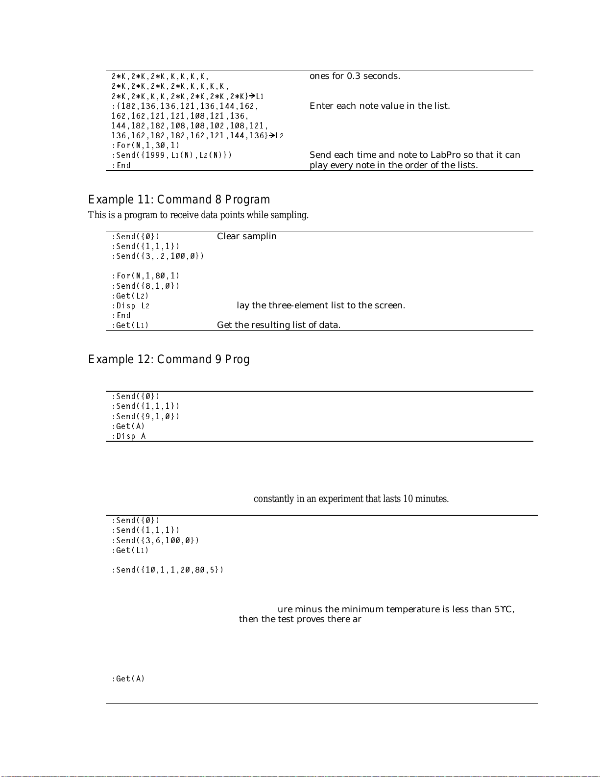
Revision Date: 08/02/02
.......
........
........`/
^
`/
)RU1
6HQG^/
(QG
1/1`
Example 11: Command 8 Program
This is a program to receive data points while sampling.
6HQG^`
6HQG^`
6HQG^`
)RU1
6HQG^`
*HW/
'LVS /
(QG
*HW/
Clear sampling settings.
Set up Channel 1 with auto-ID.
Take 100 samples in 20 seconds.
Use a loop to get samples as they are taken.
Ask for Channel 1’s last sampled data point.
Get the sensor type, most recent data point, and position in list.
Display the three-element list to the screen.
Get the resulting list of data.
Example 12: Command 9 Program
This is a program used to read a single data point.
ones for 0.3 seconds.
Enter each note value in the list.
Send each time and note to LabPro so that it can
play every note in the order of the lists.
6HQG^`
6HQG^`
6HQG^`
*HW$
'LVS $
Clear sampling settings.
Auto-ID a TI temperature sensor.
Send Command 9 to get a single data point from Channel 1.
Get the single data point.
Display the one data point.
Example 13: Command 10 Program
This program uses Command 10 with the Temperature Sensor. This test is used to find a sinusoidal-like
pattern in temperature as it rises and falls constantly in an experiment that lasts 10 minutes.
6HQG^`
6HQG^`
6HQG^`
*HW/
6HQG^`
*HW$
Clear sampling settings.
Auto-ID the TI temperature sensor.
Collect 1 sample every 6 seconds for 10 minutes.
Get the data for later use or display.
Send the advanced data reduction command with the heartbeat
algorithm. Set the lower threshold to 20% above the minimum
point. Set the upper threshold to 80% above the minimum point.
Set the standard temperature variance to 5ϒC. If the maximum
temperature minus the minimum temperature is less than 5ϒC,
then the test proves there are no oscillations in temperature outside
of 5ϒC in the 10-minute experiment. If the variance is more than
5ϒC, then this will count how many times it goes over the 80%
threshold level plus how many times it goes below the 20%
threshold level.
Get the number of times the samples went above the upper
threshold and went below the lower threshold (the edge count). If
the data range was less than 5ϒC, the result is zero.
LabPro Technical ManualE-4
Page 96

Revision Date: 08/02/02
$%
Divide the edges per sample by the sample time. This returns true
frequency (edges per second).
'LVS %
Display the frequency.
Example 14: Archive P rogram (Command 201)
This program stores and retrieves a data set.
6HQG^`
6HQG^`
;
:KLOH ;Ù
*HW;
(QG
6HQG^`
*HW/
^`/
^/`/
DXJPHQW///
6HQG/
"6(& (;3
6HQG^/
6WU
"
`
6HQG6WU
6HQG^/
`
&OU$OO/LVWV
6HQG^`
6HQG^`
*HW/
6HQG^/
*HW/
6HQG^/
`
`
*HW6WU
'LVS 6WU/
6HQG^/`
*HW/
'LVS /
6HQG^/`
*HW/
'LVS /
Enable “writes” to LabPro FLASH memory.
Save the data. Make room for 5 list elements. Give some
optional identification (e.g., data from Section 1.1, Experiment
2).
Wait for operation to complete.
Locate newest data set in FLASH memory. Its entry number will
be in L1[1].
Save associated data from L2 into the record.
Label the data set.
Close the data set. Saving is complete.
Reset LabPro and calculator.
Locate the most recently saved data set.
Get and display the identifying label and numbers.
Get and display the saved list data.
Restore and display the sample data. Data can be retrieved
using Command 5, which is described elsewhere in this
document.
LabPro Technical Manual E-5
 Loading...