

Page 1
1
What's Included
l Go Direct Sensor Cart
l Hook
l Flat-top rubber bumper for force sensor
l Anti-roll peg
l 4 empty collision tabs
l Micro USB Cable
Compatible Software
See www.vernier.com/manuals/g dx-cart for a list of software compatible with the
Go Direct Sensor Cart.
Getting Started
Please see the following link for platform-specific connection information:
www.vernier.com/start/gdx-cart
Bluetooth Connection
1. Install Graphical Analysis 4 on your computer, mobile device, or
Chromebook™. See www.vernier.com/ga4 for software availability.
2. Charge your Sensor Cart for at least 8hours before first use.
3. Turn on your Sensor Cart by pressing the power button once. The
Bluetooth®LED will blink red.
4. Launch Graphical Analysis 4.
5. Click or tap Sensor Data Collection.
6. Click or tap your Go Direct Sensor Cart from the list of Discovered W ireless
Devices. Your sensor's ID is located near the barcode on the sensor. The
Bluetooth LED will blink green when it is successfully connected.
7. The active channel is listed in the Connected Devices Sensor Channels list.
To change channels, select the check box next to the Sensor Channel(s) you
would like to activate.
8. Click or tap Done to enter data-collection mode.
Charging the Sensor Cart
Connect the Go Direct Sensor Cart to the included Micro USB Cable and any
USB device for eight hours.
You can also charge up to eight Go Direct Sensor Carts using our Go Direct
Charge Station, sold separately (order code: GDX-CRG).
Charging
Orange LED next to battery icon is solid while
sensor is charging.
Fully charged
Green LED next to battery icon solid when
sensor is fully charged.
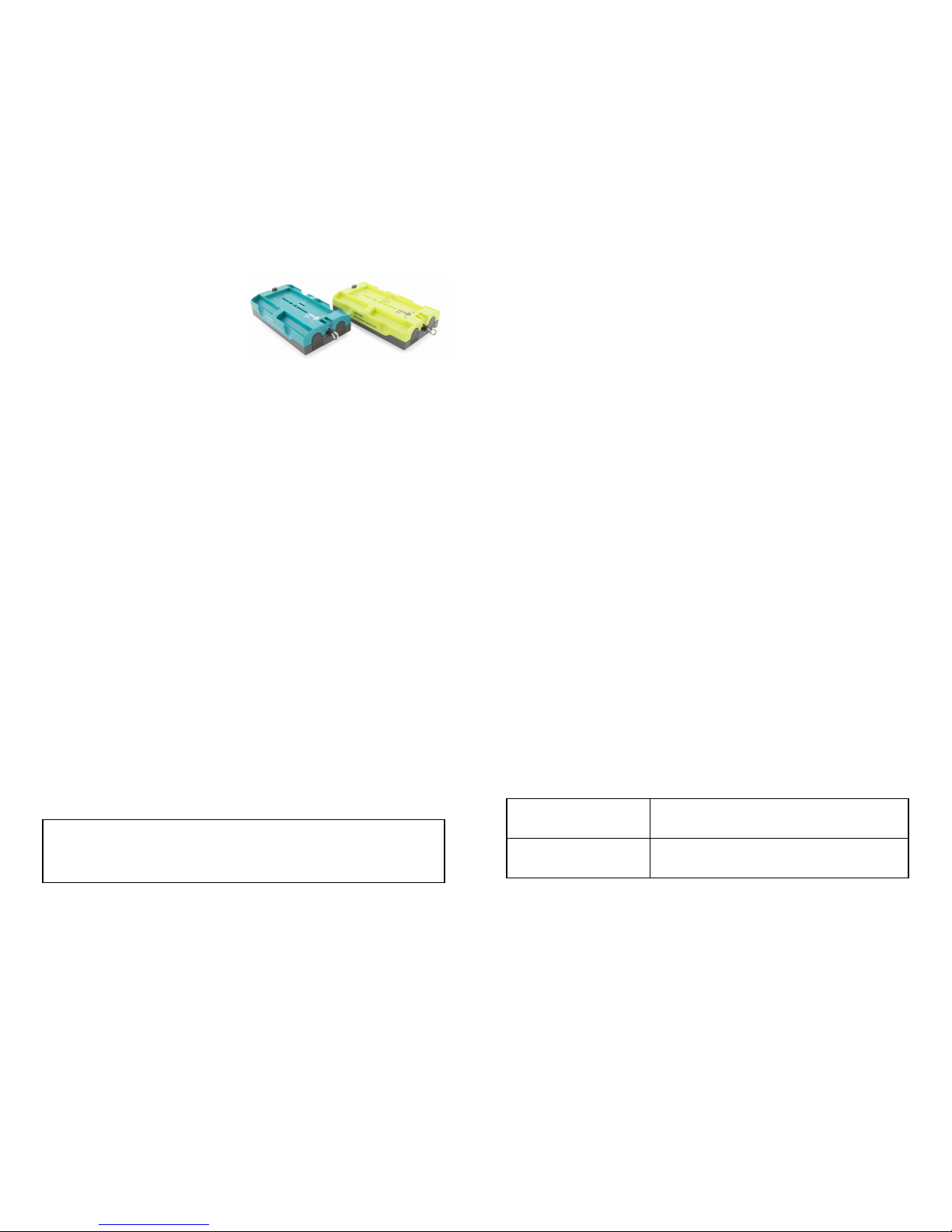
Go Direct
®
Sensor Cart
(GDX-CART-G) - Green
(GDX-CART-Y) - Yellow
Go Direct Sensor Cart can be used for hands-on kinematics and dynamics
demonstrations but can also be used as a force or acceleration sensor. Hang a
mass and spring from the force sensor to study simple harmonic motion, or
attach the cart to a turntable to study centripetal acceleration.
Each dynamics cart includes
l Encoder wheel to report position
l 3-axis accelerometer to measure independent acceleration
l 50 N force sensor to measure push and pulls
l Mass trays for changing total mass
l Plunger for collision and impulse studies
l Low friction wheels for uniform motion
l Anti-roll peg
The Go Direct Sensor Cart can be used in a variety of experiments:
l Collect position, velocity, and acceleration data as the cart rolls freely up
and down an incline.
l Observe collisions between two carts, test for the conservation of
momentum, or measure energy changes during different types of collisions.
l Investigate the relationship between force, mass, and acceleration.
l Examine the energies involved in simple harmonic motion.
l Measure a cart’s momentum change and compare it to the impulse it
receives.
Go Direct Sensor Cart connects directly to your mobile device, Chromebook™,
or computer using our free Graphical Analysis™ 4 app.
Go Direct Sensor Cart is available in green and yellow in order to facilitate
classroom discussions about collisions. The two colors are designed to be
distinguishable by many color-blind viewers.
Data column names have a suffix of Y or G so that you can tell the carts apart
in a data table. When only one cart is used, disregard the suffix.
Note: Vernier products are designed for educational use. Our products are not
designed nor are they recommended for any industrial, medical, or commercial
process such as life support, patient diagnosis, control of a manufacturing
process, or industrial testing of any kind.
Page 2

2
Channels
Go Direct Sensor Cart has five measurement channels. The channel names are
l Position
l Force
l X-axis acceleration
l Y-axis acceleration
l Z-axis acceleration
Position
The default channel that is active when the cart is first connected is position.
Graphical Analysis calculates velocity and acceleration data from the position
information. The position reading changes as the encoder wheel turns. If the cart
is picked up and moved to a different location without rolling the encoder
wheel, the position reading does not change. The behavior is like the mouse on
a computer.
Force
The default channel that is active when the sensor is connected is force. The
force channel measures pushes and pulls along the main axis of the sensor body.
Use the hook attachment for pulling and the bumper attachment for pushing.
Pulls are registered as positive forces and pushes are registered as negative
forces, unless sensor readings are reversed in Graphical Analysis 4.
Do not twist or remove the hex barrel of the force sensor. Removal will damage
the load cell.
Acceleration
There are three acceleration channels, measured by a single chip, which is
located under the 3-axis icon on the label. The icon shows the positive direction
for each axis, with the x-direction of acceleration parallel to the pulling force on
the force sensor and the z-direction straight up through the label. Each direction
of acceleration can be measured separately.
If you choose to activate all three acceleration channels at once, you can create
a calculated column for the total acceleration magnitude.
Track Usa ge Notes
The Sensor Cart can be used with or without a track. Using the cart on a
tabletop or floor allows very easy experiment setup, but a track allows more
careful experiments, including collisions, to be performed.
The Sensor Cart is compatible with many common dynamics tracks, including
the Vernier Combination 1.2 m Track and Optical Bench.
Anti-Roll Peg
The cart includes an anti-roll peg. The peg rides in the center groove of a
Vernier Track, allowing the cart to roll freely. When the cart is placed on a
table, the peg keeps the cart from rolling. If you want to use the cart on a table
or floor, remove the peg by pulling and twisting.
Powering the Cart
Turn on the cart
Press button once. Red LED indicator next to
Bluetooth icon flashes when unit is on.
Put the cart in sleep mode
Press and hold button for more than three
seconds to put into sleep mode. Red LED
indicator stops flashing when sleeping.
Connecting the Sensor Cart
See the following link for up-to-date connection information:
www.vernier.com/start/gdx-cart
Connecting via Bluetooth
Ready to connect Red LED next to Bluetooth icon flashes when
sensor is awake and ready to connect.
Connected Green LED next to Bluetooth icon flashes w hen
sensor is connected via Bluetooth.
Connecting via USB
Connected and charging Orange LED next to battery icon is solid when
sensor is connected to Graphical Analysis via
USB and the unit is charging. LED next to
Bluetooth is off.
Connected, fully charged Green LED next to battery icon is solid when
sensor is connect to Graphical Analysis via USB
and fully charged. LED next to Bluetooth icon is
off.
Charging via USB,
connected via Bluetooth
Orange LED next to battery icon is solid when
sensor is connected to charger via USB and the
unit is charging. Green LED next to Bluetooth
icon flashes when sensor is connected via
Bluetooth.
Identifying the Sensor
You can make the Bluetooth LED flash red and green by clicking Identify in
Sensor Information. This is useful to distinguish between two identical sensors.
Using the Sensor Cart
Connect the sensor following the steps in the Getting Started section of this user
manual.
Page 3

3
The force sensor can be zeroed. This is useful after calibration to remove the
weight of the hook. The force sensor can also be reversed so that push is
positive.
X, Y, and Z Acceleration in m/s
2
This sensor is factory calibrated.
Specifications
Position resolution 0.25 mm, displaying to nearest 1 mm
Nominal mass 275 g excluding accessories
Accessory port Available for future expansion
Force response time 1 ms
Force range ±50 N
Acceleration range ±160 m/s
2
USBspecification USB 2.0 full speed
Wireless specification Bluetooth v4.2
Maximum wireless
range
30 m (unobstructed)
Dimensions Length: 16.6 cm, not including accessories mounted
to the force sensor
Width: 9.6 cm
Height: 4.7 cm
Battery 650 mAh Li-Poly Rechargeable
Battery life (single full
charge)
~10 hours continuous data collection
Battery life (long term) ~300 full charge cycles (several years depending on
usage)
Safety
The wheels are spring-loaded so that they will retract when excessive force is
applied, as when stepping on the cart.
Plunger
The cart includes a spring-loaded plunger for collisions. To use the plunger,
simultaneously press the horizontal button above the plunger and press the
plunger in until it locks. To release, press on the pin from the top of the cart.
The plunger force can be adjusted. To adjust the plunger release force, rotate the
plunger while it is extended. An uncalibrated scale is visible on the underside
of the cart. Use this scale to return to a previous setting. The plunger cart is
capable of superelastic collisions. To enable this mode, use a small screwdriver
to unlock the dark gray plastic plug below the main plunger. Depress the plug
using the screwdriver and rotate one-quarter turn counterclockwise to unlock.
The plug will extend about 2 mm. Lock the plunger as before to prepare for a
superelastic collision. In a collision, the plug will strike first and trigger the
release of the plunger. To disable superelastic collision mode, use a small
screwdriver to depress and rotate the plug one-quarter turn clockwise. It will
lock in the flush position.
Available Sensor Cart Accessory Kit (order code GDX-CART-AK)
An accessory kit for the Vernier Go Direct Sensor Cart is available. The kit is
recommended for more advanced users. It includes
l Hoop spring bumper (heavy)
l Hoop spring bumper (light)
l Magnet tabs (4)
l Hook-and-pile tabs (4 pair)
l Masses (4 hex)
l Magnetic disk bumper for force sensor (2)
l Additional metal hook and nut for force sensor (3)
l Additional flat-top rubber bumper (3)
l Additional anti-roll pegs (3)
Calibrating the Sensor Cart
Position in m
The position channel does not need to be calibrated, nor can it be calibrated.
The position channel can be zeroed. This is useful to establish a zero position
on a track. Do not pick up the cart after zeroing to avoid disturbing the zero.
The position sensor can also be reversed. This is useful when using two carts in
collision mode with force sensors facing one another. To put the two carts on
the same coordinate system, reverse the direction of the position and force
sensors on one cart, and zero the cart positions with the carts in contact.
Force in N
This sensor is factory calibrated. If you would like to calibrate the force sensor
yourself, use a two-point calibration: no force applied and a known force
applied. It is easiest to simply hang a mass from the hook. We recommend a
1kg mass. Do not exceed the maximum of 50 N during calibration.
Page 4

4
Accelerometer
The accelerometer is a microelectromechanical device (MEMS device)
consisting of a cantilever and a test mass. As the mass is accelerated, the
cantilever bends, generating a signal proportional to the acceleration. Three
orthogonal axes provide three channels of acceleration information.
Additional Information about Accelera tion
Since the accelerometer is sensitive to both acceleration and the Earth’s
gravitational field, interpreting accelerometer measurements is complex. A useful
model for understanding accelerometer measurements is a spring-based scale
with a reference mass (or object) attached to the scale. If the scale is pointing
upward (the usual orientation for such a device) the weight of the mass causes
the spring to compress, and you get a non-zero reading. If you were to turn the
scale upside down, the spring will be extended, instead of compressed, and we
get a reading of the opposite sign. If you turn the scale so it points sideways,
and keep it motionless, then the spring will just be at its relaxed length, and the
reading will be zero. If you accelerated the scale toward the mass, then the
spring w ould compress. If you accelerate the scale away from the mass the
spring w ould stretch. In each case the scale is reading a value corresponding to
the normal force on the mass. This reading can be made relative by dividing out
the mass, giving units of N/kg, which is the same as m/s2.
Troubleshooting
For troubleshooting and FAQs, see www.vernier.com/til/4131
Repair Information
If you have followed the troubleshooting steps, and are still having trouble with
your Go Direct Sensor Cart, contact Vernier Technical Support at
support@vernier.com or call 888-837-6437. Support specialists will work with
you to determine if the unit needs to be sent in for repair. At that time, a Return
Merchandise Authorization (RMA) number will be issued and instructions will
be communicated on how to return the unit for repair.
Accessories/Replacements
Item Order Code
Sensor Cart Accesso ry Kit
GDX-CART-AK
Dynamics Cart and Track System with Go
Direct Sensor C arts
DTS-GDX
Dynamics Cart and Track System with Go
Direct Sensor C arts and Lo ng Track
DTS-GDX-LONG
Replacement Battery
GDX-BAT-650
Micro USBCab le
CB-USB-MICRO
USB-C to Micro USBCable
CB-USB-C-MICRO
Warranty
Vernier warrants this product to be free from defects in materials and
workmanship for a period of five years from the date of shipment to the
Care and Maintenance
Battery Information
The Go Direct Sensor Cart contains a small lithium-ion battery. The system is
designed to consume very little power and not put heavy demands on the
battery. Although the battery is warranted for one year, the expected battery life
should be several years. Replacement batteries are available from Vernier (order
code: GDX-BAT-650).
Storage and Maintenance
To store the Go Direct Sensor Cart for extended periods of time, put the device
in sleep mode by holding the button down for at least three seconds. The red
LED will stop flashing to show that the unit is in sleep mode. Over several
months, the battery will discharge but will not be damaged. After such storage,
charge the device for a few hours, and the unit will be ready to go.
Exposing the battery to temperatures over 35°C (95°F) will reduce its lifespan. If
possible, store the device in an area that is not exposed to temperature extremes.
Water Resista nce
The Go Direct Sensor Cart is not water resistant and should never be immersed
in water.
If water gets into the device, immediately power the unit down (press and hold
the power button for more than three seconds). Disconnect the sensor and
charging cable and remove the battery. Allow the device to dry thoroughly
before attempting to use the device again. Do not attempt to dry using an
external heat source.
How the Sensor Works
Position
The position channel uses an optical encoder system. As the sensing wheel
rotates, the position of attached disc with radial markings is detected by a pair
of optical sensors. From counting the events and their sequence, the angle
turned as well as its sense of rotation can be determined. The angle is converted
to a change in position using the diameter of the sensing wheel. Since the wheel
does not turn if the cart is not on a surface, the reading will not change if the
cart is repositioned by lifting.
A result of the design is that there is no natural zero for the sensor. The position
when the cart is first connected to software is thus used as a zero. The position
channel can be zeroed in software as desired.
Velocity and acceleration are calculated in software from the position and time
data.
Force
The force channel uses strain gauge technology to measure force based on the
bending of a beam in a load cell.
Page 5

5
(2)l ’appareil doit accepter tout interférence radioélectrique, même si cela résulte à un brouillage s usceptible d’en compromettre le
fonctionnement.
Cet appareil numérique respecte l es li mites de bruits radioélec triques applic ables aux appareils numériques de Cl asse B prescrites dans
la norme sur l e matériel interférant-brouilleur: “Appareils Numériques,” NMB-003 édictée par industrie Canada. L’util isation est soumise
aux deux conditions sui vantes:
(1)c et appareil ne peutc auser d’interférences, et
(2)c et appareil doit accepter toutes interférences, y comprises cell es s usceptibles de provoquerun disfonctionnement du dis positif.
Afin de réduire les interférences radio potentiell es pour les autres utilis ateurs, le type d’antenne et son gain doivent être chois ie de tel le
façon que l ’équivalent depui ssance i sotrope émis (e.i.r.p)n’ est pas plus grand que celui permis pour une communic ation établie.
Avertissement d’exposition RF: L’équipement est conforme aux limites d’ exposition aux RF établies pourun envi ronnementnon
supervisé. L’ antenne (s) utilis ée pour ce transmetteur ne doit pas être jumelés oufoncti onner en conjoncti on avec touteautre antenne ou
transmetteur.
Note: This product is a sensitive measurement devic e. For best results, use the cables that wereprovided. Keep the device away from
electromagnetic nois e sources, such as mi crowaves, monitors, elec tric motors, and appli ances.
Vernier Software & Technology
13979 SW Millikan Way • Beaverton, OR 97005-2886
Toll Fr ee (888) 837-6437 • (503) 277-2299 • Fax (503) 277- 2440
info@vernier.com • www.vernier.com
Rev. 3/27/1 8
Go Direct, Graphical An alysis , and other marks shown are our trademarks or regis tered trademarks in the Unit ed
States. All ot her marks not ow ned by us that appear herein are the property of their respecti ve owners, who may
or may not be affiliated wit h, connected to, or spons ored by us.
The Bluetoo th®word mark and logos are regist ered trademarks owned by the Bluetoo th SIG, Inc. and any us e of
such marks by Vernier Software & Technolog y is under licens e. O ther trademarks and trade names are tho se of
their respecti ve owners.
customer. This warranty does not cover damage to the product caused by abuse
or improper use. This warranty covers educational institutions only.
Disposal
When disposing of this electronic product, do not treat it as household waste. Its
disposal is subject to regulations that vary by country and region. This item
should be given to an applicable collection point for the recycling of electrical
and electronic equipment. By ensuring that this product is disposed of correctly,
you help prevent potential negative consequences on human health or on the
environment. The recycling of materials will help to conserve natural resources.
For more detailed information about recycling this product, contact your local
city office or your disposal service.
Battery recycling information is available at www.call2recycle.org
Do not puncture or expose the battery to excessive heat or flame.
The symbol, shown here, indicates that this product must not be disposed of
in a standard waste container.
Federal Communication Commission Interference Statement
This equipment has been tested and found to comply with the limits fora Clas s B digital devi ce, pursuant to Part 15 of the FCCrules .
These limi ts are designed toprovi de reasonable protection against harmful i nterference in aresi dential ins tallation. This equi pment
generates, uses and can radiate radio frequency energy and, i f not ins talled and used in acc ordance with the ins tructions, may cause
harmful interference to radio communic ations. However, there is noguarantee that i nterference will not occur in a particular instal lation. If
this equi pment does cause harmful i nterference to radio or tel evisi on reception, which can be determined by turning the equipmentoff and
on, the user i s encouraged to try to correct the interference by one or more of thefol lowing measures:
Reorient or relocate the receivi ng antenna.
Increase the separation between the equipmentand receiver.
Connect the equipment i nto an outlet on a circuit different from that to whic h the receiv er is c onnected.
Consult the deal er or an experienced radio/TV technic ian for help.
FCC C aution
This devi ce compli es with Part 15 of theFCC Rules. Operation is subject tothe following two conditi ons:
(1)thi s devi ce may notc ause harmful interference and
(2)thi s devi ce must accept any i nterference received, including interference that may cause undesired operation
RF Exposure Warning
The equipment complies with RF exposure limi ts set forthfor an uncontrolled envi ronment.The antenna(s) used for thi s transmitter must
not be co-loc ated or operating in conj unction with any other antenna or transmitter. You are cautioned that changes or modifications not
expressly approved by the party responsible for c ompliance c ould voi d your authority to operate the equipment.
IC Statement
This devi ce compli es with Industry Canada li cense-exempt RSS s tandard(s). Operation is subject to thefol lowing two condi tions:
(1)thi s devi ce may notc ause interference, and
(2)thi s devi ce must accept any i nterference, incl uding interference that may cause undesired operation of the device.
Industry Canada- ClassB This digital apparatus does not exceed the Class B limi ts for radio nois e emiss ions from digi tal apparatus
as set out in the i nterference-causing equipment standard entitled “Digital A pparatus,”ICES-003 of Industry Canada. Operation is subject
to the foll owing two conditi ons: (1) this device may not cause interference, and
(2)thi s devi ce must accept any i nterference, incl uding interference that may cause undesired operation of the device.
To reduce potential radio interference to other users, the antenna type andi ts gain should be so chosen that the equiv alent is otropically
radiated power(e.i.r.p.) is not more than that permitted for succ essful c ommunication.
RF exposure warning: The equipment complies with RF exposure li mits s et forth for an uncontrolled env ironment. Theantenna(s) used
for this transmitter mus t not be c o-located or operating in c onjunction with any other antenna or transmitter.
Le présent appareil es t conforme aux CNR d’Industrie Canada applicabl es aux appareils radio exempts de licence. L’exploitation est
autorisée aux deux conditions suivantes :
(1)l ’appareil ne doi t pas produire de brouil lage, et
 Loading...