

Page 1

1
blink green when it is successfully
connected.
7. This is a multi-channel sensor. The
active channel is listed in the
Connected Devices Sensor
Channels list. To change channels,
select the check box next to the
Sensor Channel(s) you would like
to activate.
8. Click or tap Done to enter
data-collection mode.
Charging the Sensor
Connect Go Direct 3-Axis Magnetic Field to the included Micro USB Cable
and any USB device for two hours.
You can also charge up to eight Go Direct 3-Axis Magnetic Field Sensors using
our Go Direct Charge Station, sold separately (order code: GDX-CRG).
Charging
Blue LED is on steady and a red LEDis flashing
while sensor is connected to the Micro USB
Cable or Charge Station.
Fully charged
Blue LED is off when charging is complete.
Powering the Sensor
Turning on the sensor
Press button once. Red LED indicator flashes
when unit is on.
Putting the sensor in sleep
mode
Press and hold button for more than three
seconds to put into sleep mode. Red LED
indicator stops flashing when sleeping.
Connecting the Sensor
See the following link for up-to-date connection information:
www.vernier.com/start/gdx-3mg
Connecting via Bluetooth
Ready to connect Red LED flashes when sensor is awake and
ready to connect.
Connected Green LED flashes when sensor is connected via
Bluetooth and taking data.
Go Direct®3-Axis
Magnetic Field
(Order Code GDX-3MG)
Go Direct 3-Axis Magnetic Field allows you to
determine the magnitude and direction of the magnetic field at any point in
space. It directly connects wirelessly via Bluetooth®or wired via USB to your
platform.
Note: Vernier products are designed for educational use. Our products are not
designed nor are they recommended for any industrial, medical, or commercial
process such as life support, patient diagnosis, control of a manufacturing
process, or industrial testing of any kind.
What's Included
l Go Direct 3-Axis Magnetic Field
l Rechargeable battery (included inside unit)
l Micro USBCable
Compatible Software
See www.vernier.com/manu als/gdx-3mg for a list of software compatible with Go
Direct 3-Axis Magnetic Field.
Getting Started
Please see the following link for platform-specific connection information:
www.vernier.com/start/gdx-3mg
Bluetooth Co nnection USB Connection
1. Install Graphical Analysis 4 on
your computer, Chromebook™, or
mobile device. See
www.vernier.com/ga4 for software
availability.
2. Charge your sensor for at least
2hours before first use.
3. Turn on your sensor by pressing
the power button once. The
Bluetooth®LED will blink red.
4. Launch Graphical Analysis 4.
5. Click or tap Sensor Data
Collection.
6. Click or tap your Go Direct sensor
from the list of Discovered
Wireless Devices. Your sensor's ID
is located near the barcode on the
sensor. The Bluetooth LED will
1. If using a computer or Chromebook,
install Graphical Analysis 4. If using
LabQuest 2, make sure LabQuest
App is up to date. See
www.vernier.com/ga4 for Graphical
Analysis 4 availability or
www.vernier.com/downloads to
update LabQuest App.
2. Connect the sensor to the USB port.
3. Launch Graphical Analysis 4 or turn
on LabQuest 2. You are now ready
to collect data.
4. This is a multi-channel sensor. To
change the default channel
selections, see
www.vernier.com/start/gdx-3mg
Page 2
2
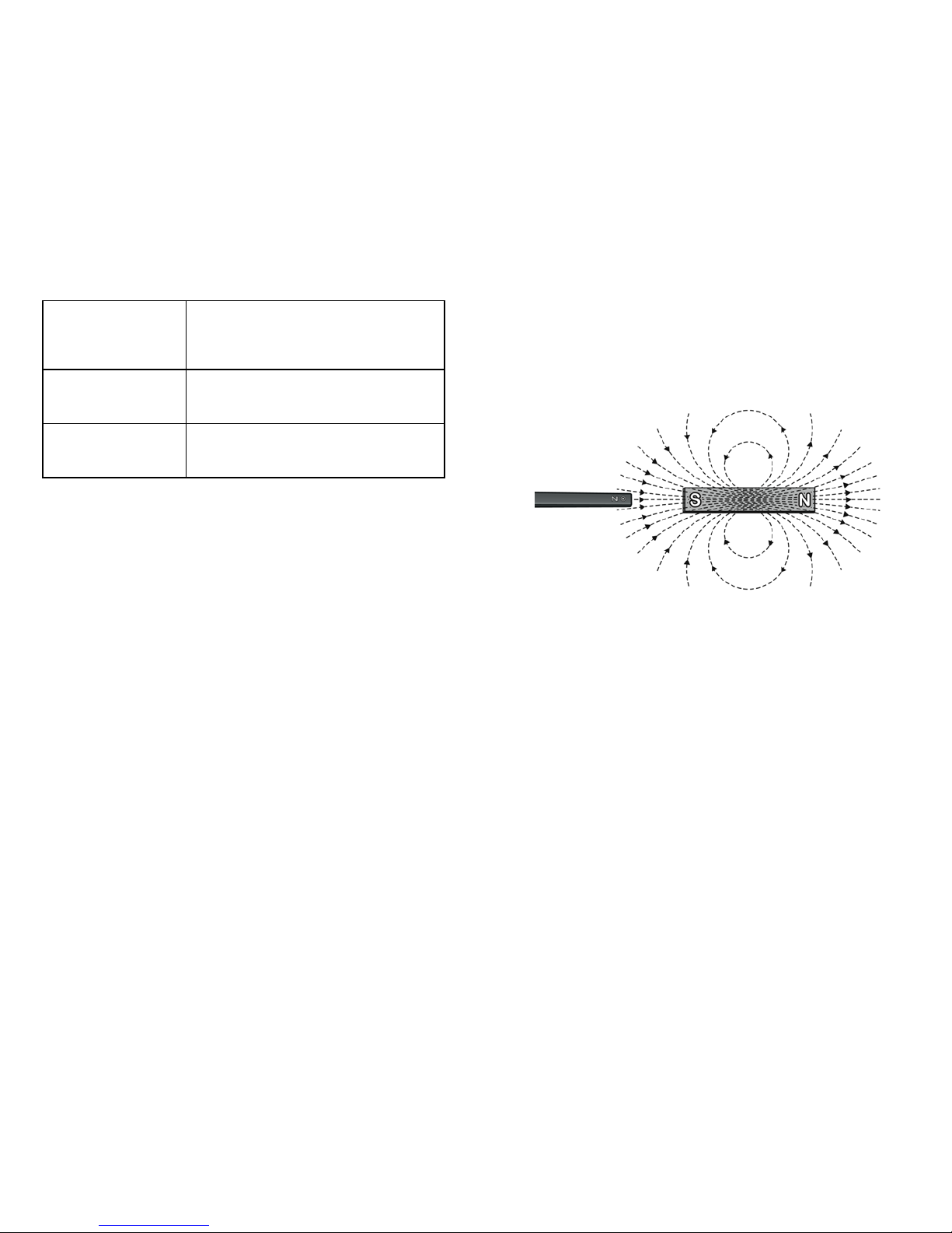
Measuring the X-direction Magnetic Field
Magnetic fields that point in the same direction the wand is pointing are
recorded as positive, and fields that point in the opposite direction are recorded
as negative. Thus, the magnetic field of the Earth will register as a positive field
when the wand is pointed toward the magnetic pole in the Earth’s northern
hemisphere, which is a South magnetic pole. When the wand is aligned with a
permanent magnet and pointed toward the South pole of a magnet it will also
record a positive field.
The x-direction measurement is positive when the wand points toward the South
pole of a magnet.
Measuring y- and/or z-directions
The marks on the sides of the wand, at the tip, indicate the y- and z-directions
of positive magnetic field measurements, as well as marking the location within
the housing where the ±5 mT magnetic field sensor is located. This is important
for consistent placing of the sensor and accurately measuring the distance
between the sensor and the source of a magnetic field.
Connecting via USB
Connected and charging Blue and green LED solid when sensor is con-
nected to Graphical Analysis via USB and unit
is charging. (Green LED is obscured by the blue
one.)
Connected, fully charged Green LED solid when sensor is connected to
Graphical Analysis via USB and the unit is fully
charged.
Charging via USB,
connected via Bluetooth
Blue LED is solid and green LED is flashing, but
the green flashing LED looks white because it is
overwhelmed by the blue.
Identifying the Sensor
When two or more sensors are connected, the sensors can be identified by
tapping or clicking Identify in Sensor Information.
Using the Product
Connect the sensor following the steps in the Getting Started section of this user
manual.
Channels
Go Direct 3-Axis Magnetic Field has 6 measurement channels. The channel
names are
l X magnetic field
l Y magnetic field
l Z magnetic field
l X magnetic field 130mT
l Y magnetic field 130mT
l Z magnetic field 130mT
The default channel that is active when connected is the X magnetic field
channel, which has a maximum range of ±5 mT. This range works well for the
experiments we have published in our lab manuals.
There are two additional channels that use the ±5 mT range, Y magnetic field
and Z magnetic field. The y- and z-directions are indicated by the dots
impressed in the plastic near the end of the wand. These marks also indicate the
location of the actual sensor chip within the wand.
When using any of the ±5 mT channels, if the sensor is exposed to a magnetic
field greater than ±5 mT on any axis, the software will display a reading of 5
mT. To measure the field strength of stronger magnetic fields, use the 130 mT
channels. The 130 mT channels are measured by a second sensor chip inside the
wand, located 5.5 mm toward the handle from the dots in the end of the wand.
Page 3

3
Specifications
Measurement range ±5 mT and ±130 mT
Sensor location ±5 mT sensor location is indicated by
dots on wand, about 5mm from the wand
tip.
±130 mT sensor location is about
10.5mm from the wand tip.
Maximum data-collection rate 100 Hz
Resolution 0.00015 mT on ±5 mT range
0.1 mT on ±130 mT range
USB specification USB 2.0 full speed
Wireless specification Bluetooth v4.2
Maximum wireless range 30 m (unobstructed)
Dimensions 19 cm long, wand portion 12.2 cm long
Wand tapers from 0.8 cm square at
handle to 0.7 cm square at tip. This
sensor is designed to be placed inside a
solenoid if needed.
Battery 300 mA Li-Poly
Battery life (single full charge) ~24 hours continuous data collection
Battery life (long term) Several years depending on usage
Care and Maintenance
Battery Information
Go Direct 3-Axis Magnetic Field contains a small lithium-ion battery in the
handle. The system is designed to consume very little power and not put heavy
demands on the battery. Although the battery is warranted for one year, the
expected battery life should be several years. Replacement batteries are available
from Vernier (order code: GDX-BAT-300).
Storage and Maintenance
To store Go Direct 3-Axis Magnetic Field for extended periods of time, put the
device in sleep mode by holding the button down for at least three seconds. The
red LED will stop flashing to show that the unit is in sleep mode. Over several
months, the battery will discharge but will not be damaged. After such storage,
charge the device for a few hours, and the unit will be ready to for use.
Exposing the battery to temperatures over 35°C (95°F) will reduce its lifespan. If
possible, store the device in an area that is not exposed to temperature extremes.
In this orientation, the z-direction measurement will be positive.
Measuring Magnitude
This sensor measures just the vector component of the field along each
direction. To determine the total magnetic field strength at a location, you could
measure only in the x-direction (the default setting in Graphical Analysis) and
point the wand exactly in the direction of the magnetic field in the location you
are measuring. Another option is to create a calculated column in software. The
magnitude of the field is calculated as the square root of the sum of the squares
of the measurements along all three axes. Using this method may be useful with
students who have been introduced to vectors in three dimensions.
Calibrating the Sensor
User calibration is not available for this sensor. We have set the sensor to match
our stored calibration before shipping it.
It is useful, however, to zero Go Direct 3-Axis Magnetic Field. Position the
sensor and zero it using your data-collection software. Moving the sensor will
upset the zero since the background magnetic field in your lab probably varies
with position. For experiments measuring the spatial variation of a magnetic
field, it is better to zero the sensor and then move the source to various
positions.
Page 4

4
Battery recycling information is available at www.call2recycle.org
Do not puncture or expose the battery to excessive heat or flame.
The symbol, shown here, indicates that this product must not be disposed of
in a standard waste container.
Federal Communication Commission Interference Statement
This equipment has been tes ted and found to comply with the limits for a Class B digital devic e, pursuant to Part 15 of the FCC rules.
These limi ts are designed to provide reasonable protection against harmful i nterference in a residential installati on. This equipment
generates, uses and can radiate radio frequency energy and, if not install ed and us ed in accordance with the ins tructions, may cause
harmful interference to radio communications. However,there i s no guaranteethat interference will not occur in a particular instal lation. If
this equipment does c ause harmful interference to radio or televi sion reception, which can be determined by turning the equi pment off and
on, the us er is encouraged to try to correct the interference by one or more of the following measures:
Reorient or relocate the receiving antenna.
Increase the separation between the equipment and receiver.
Connect the equipment into an outlet on a circuit different from that to which the receiver is connected.
Consult the dealer or an ex perienced radio/TV technic ian for hel p.
FCC Caution
This devi ce c omplies with Part 15 of the FCC Rules. Operation is subject to the following two conditions:
(1)thi s dev ice may not cause harmful i nterference and
(2)thi s dev ice must acc ept any interference receiv ed, inc luding interference that may cause undesired operation
RF Exposure Warning
The equipment compli es wi th RF exposure l imits set forthfor an uncontrolled envi ronment. The antenna(s)us ed for this transmitter must
not be c o-located or operating i n c onjunction with any otherantenna ortransmitter. You are cautioned that changes ormodi fications not
expressly approved by the party responsibl e for c ompliance could voi d your authority to operate the equipment.
IC Statement
This devi ce c omplies with Industry Canada license-exempt RSS standard(s). Operation is subjec t to the following two conditions:
(1)thi s dev ice may not cause interference, and
(2)thi s dev ice must acc ept any interference, i ncluding interference that may cause undesi red operation of the device.
Industry Canada - C lassB This digi tal apparatus does not ex ceed the Class B limi ts for radio noise emissions from digital apparatus
as s et out in the interference-causing equi pment standard entitled “Digital Apparatus,” ICES-003 of Industry Canada. Operation i s s ubject
to the following two c onditions: (1)thi s dev ice may not c ause i nterference, and
(2)thi s dev ice must acc ept any interference, i ncluding interference that may cause undesi red operation of the device.
To reduce potential radio interference to other us ers, the antenna type and i ts gain should be so chosen that the equival ent is otropically
radiated power (e.i.r.p.)i s not more than that permitted for successful communicati on.
RF exposure warning: The equipment complies with RF exposure l imits set forthfor an uncontrolled envi ronment. The antenna(s)us ed
for this transmitter must not be co-located or operating in c onjunction with any other antenna or transmitter.
Le présent appareil est c onformeaux CNR d’Industrie Canada applicables aux appareils radio exempts de li cence. L’exploitation est
autorisée aux deux condi tions suivantes :
(1)l ’appareil ne doit pas produire de brouill age, et
(2)l ’appareil doit accepter tout interférence radioélectrique, même s i cela résulte à un brouillage susc eptible d’en compromettre le
fonctionnement.
Cet appareil numérique respecte les limites de bruits radioélectriques appli cables aux appareils numériques de Classe B prescrites dans
la norme s ur le matériel interférant-brouilleur: “Appareils Numériques,” NMB-003 édictée par industrie Canada. L’ utilis ation es t soumis e
aux deux conditions suiv antes:
(1)c et appareil ne peut caus er d’interférences, et
(2)c et appareil doit acc epter toutes i nterférences, y comprises cell es s usceptibles de provoquer un disfonctionnement du dispositi f.
Afin de réduire les interférences radio potentielles pour les autres utili sateurs, le type d’ antenne et s on gain doivent être c hoisie de tell e
façon que l’équival ent de pui ssance isotrope émis (e.i.r.p)n’ est pas plus grand que celui permis pourune communication établie.
Avertissement d’exposition RF: L’équipement es t conforme aux limi tes d’ exposition aux RF établi es pourun environnement non
supervisé. L’antenne (s) utili sée pour c e transmetteur ne doi t pas être jumelés ou fonctionner en conjonction avec toute autre antenne ou
transmetteur.
Note: This product i s a sensiti ve measurement devi ce. For best results, use the c ables that were provided. Keep the device away from
electromagnetic noi se s ources, suc h as microwaves, monitors, electric motors, and appli ances.
Water Re sistance
Go Direct 3-Axis Magnetic Field is water resistant and can be submerged in
water for limited periods of time. However, submerging the sensor impacts the
radio operation by absorbing much of the energy. This may make it difficult or
impossible to connect to the sensor while submerged, particularly if there are
electrically noisy signals nearby such as pumps or motors.
How the Sensor Works
The ±5 mT chip in Go Direct 3-Axis Magnetic Field uses a device based on
anisotropic magnetoresistance. In certain materials, the electrical resistance
varies with the external magnetic field strength and the angle between the
current and the field. Using this effect one can measure the component of the
magnetic field along each axis.
The ±130 mT chip in the sensor uses a Hall-effect transducer. It produces a
voltage that is linear with magnetic field.
Repair Information
If you have followed the troubleshooting steps and are still having trouble with
your Go Direct 3-Axis Magnetic Field, contact Vernier Technical Support at
support@vernier.com or call 888-837-6437. Support specialists will work with
you to determine if the unit needs to be sent in for repair. At that time, a Return
Merchandise Authorization (RMA) number will be issued and instructions will
be communicated on how to return the unit for repair.
Accessories/Replacements
Item Order Code
Replacement Bat tery
GDX-BAT-300
Micro USBCable
CB-USB-MICRO
USB-C to Micro USBCable
CB-USB-C-MICRO
Warranty
Vernier warrants this product to be free from defects in materials and
workmanship for a period of five years from the date of shipment to the
customer. This warranty does not cover damage to the product caused by abuse
or improper use. This warranty covers educational institutions only.
Disposal
When disposing of this electronic product, do not treat it as household waste. Its
disposal is subject to regulations that vary by country and region. This item
should be given to an applicable collection point for the recycling of electrical
and electronic equipment. By ensuring that this product is disposed of correctly,
you help prevent potential negative consequences on human health or on the
environment. The recycling of materials will help to conserve natural resources.
For more detailed information about recycling this product, contact your local
city office or your disposal service.
Page 5

5
Vernier Software & Technology
13979 SW Millikan Way • Beaverton, OR 97005-2886
Toll Fr ee ( 888) 837-6437 • ( 503) 277-2299 • F ax (503) 277-2440
info@vernier.com • www .vernier.com
Rev. 04/0 2/18
Go Di rect, Graphical Analys is, Lab Quest , and ot her marks sh own are ou r trademarks o r regist ered trademarks in
the Un ited States. All other marks not o wned b y us that ap pear herein are th e propert y of t heir respect ive
owners, wh o may or may n ot b e affiliat ed wit h, conn ected to, o r spon sored b y us .
The Blu etoot h®word mark and log os are regis tered trademarks owned b y th e Blueto oth SIG, In c. and any u se of
such marks by Verni er Software & Techno log y is under l icense. Oth er trademarks and trade names are th ose of
their res pective o wners.
 Loading...