

Page 1
®
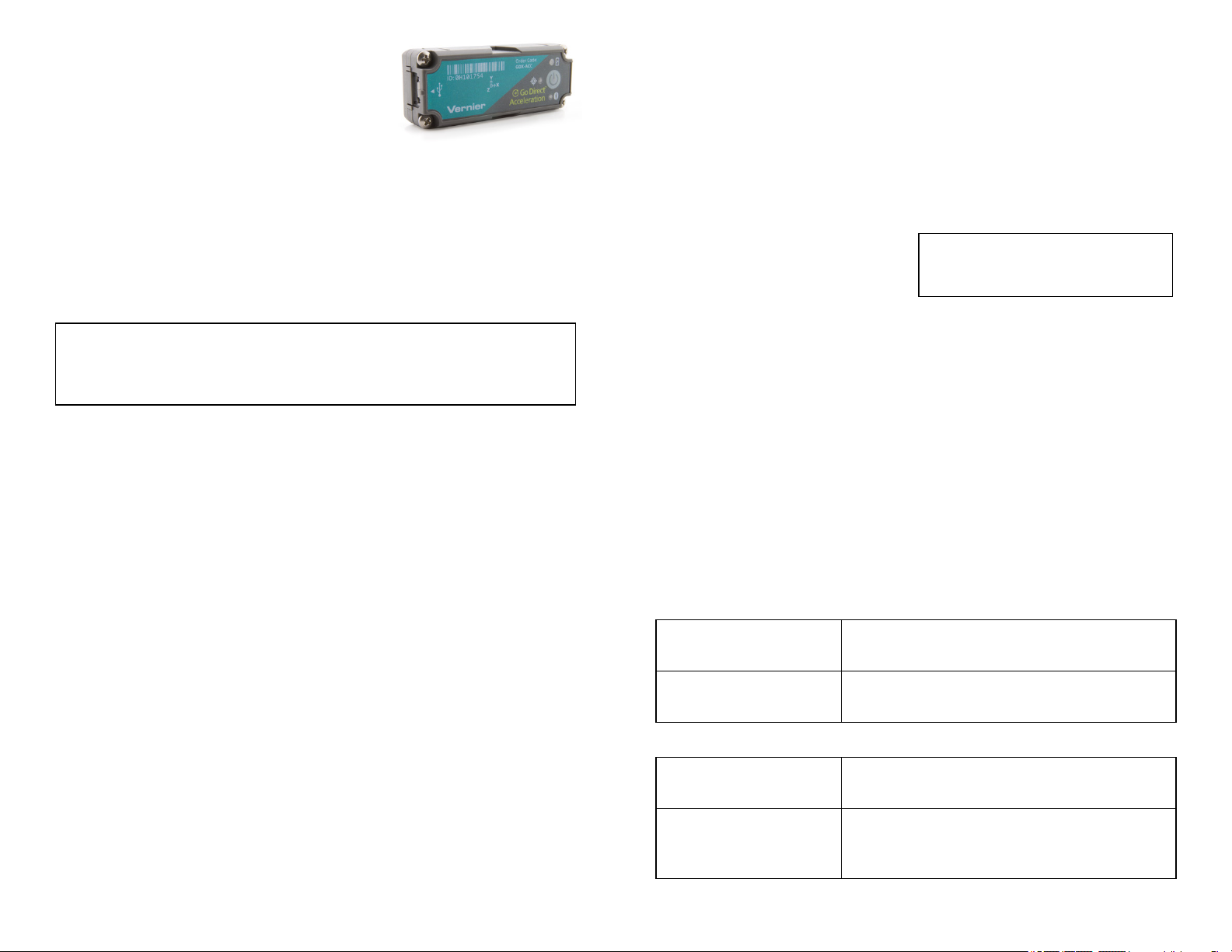
Go Direct
Acceleration
(Order Code GDX-ACC)
Collect acceleration, rotation, and altitude data in
the classroom or in the field. Go Direct Acceleration
connects wirelessly via Bluetooth®or wired via USB to your device. This 3-axis
acceleration sensor has two acceleration ranges plus an altimeter and a 3-axis
gyroscope.
l Measure helmet impacts in concussion-related investigations.
l Slip it into your pocket and pirouette or ride a half-pipe.
l Zip-tie this accelerometer to your bicycle or affix it to your lab cart without
any dragging cables.
Note: Vernier products are designed for educational use. Our products are not
designed nor are they recommended for any industrial, medical, or commercial
process such as life support, patient diagnosis, control of a manufacturing
process, or industrial testing of any kind.
What's Included
l Go Direct Acceleration
l Micro USBCable
l Shim plate for cart
l U-bracket for cart
l Cylinder mounting plate
Compatible Software
See www.vernier.com/manuals/g dx- acc for a list of software compatible with
GoDirectAcceleration.
Getting Started
Please see the following link for platform-specific connection information:
www.vernier.com/start/gdx-acc
Bluetooth Connection USB Connection
1. Install Vernier Graphical
Analysis™ on your computer,
Chromebook™, or mobile device. If
using LabQuest®, make sure
LabQuest App is up to date. See
www.vernier.com/ga4 for Graphical
Analysis availability or
www.vernier.com/downloads to
update LabQuest App.
1. If using a computer or
Chromebook, install Vernier
Graphical Analysis. If using
LabQuest, make sure LabQuest
App is up to date. See
www.vernier.com/ga4 for Graphical
Analysis availability or
www.vernier.com/downloads to
update LabQuest App.
2. Charge your sensor for at least
2hours before first use.
3. Turn on your sensor by pressing the
power button once. The Bluetooth
LED will blink red.
4. Launch Graphical Analysis or turn
on LabQuest.
5. If using Graphical Analysis, click
2. Connect the sensor to the USB
port.
3. Launch Graphical Analysis or turn
®
on LabQuest. You are now ready to
collect data.
4. This is a multi-channel sensor. To
change the channel selections, see
www.vernier.com/start/gdx-acc
or tap Sensor Data Collection. If
using LabQuest, choose Wireless
Device Setup > Go Direct from the
Sensors menu.
6. Select your Go Direct sensor from
Note: This sensor does not work with
the original LabQuest. It works with
LabQuest 2 or LabQuest 3.
the list of Discovered Wireless
Devices. Your sensor's ID is located
near the barcode on the sensor. The
Bluetooth LED will blink green
when it is successfully connected.
7. Click or tap Done. You are now
ready to collect data.
8. This is a multi-channel sensor. To
change the channel selections, see
www.vernier.com/start/gdx-acc
Charging the Sensor
Connect Go Direct Acceleration to the included Micro USB Cable and any
USB device for two hours.
You can also charge up to eight Go Direct Acceleration Sensors using our
GoDirect™ Charge Station, sold separately (order code: GDX-CRG). An LED
on each Go Direct Acceleration indicates charging status.
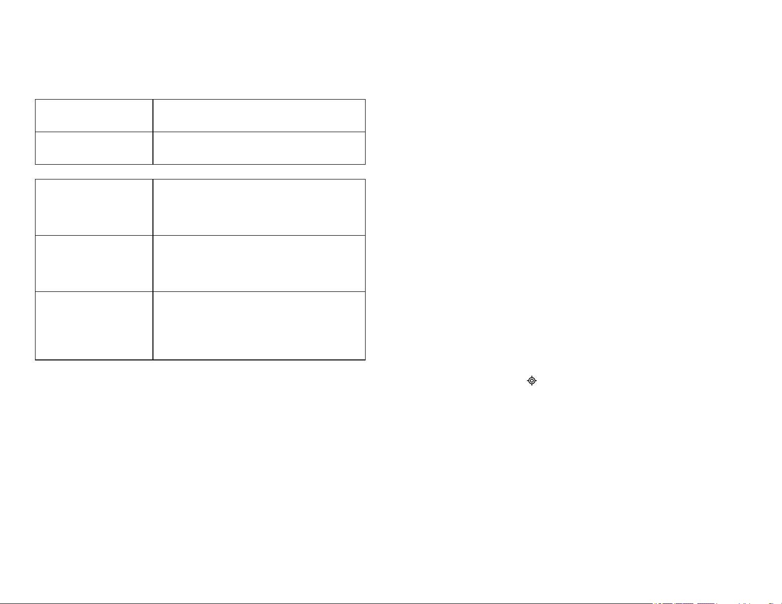
Charging
Orange LED next to battery icon is solid while
sensor is charging.
Fully charged
Green LED next to battery icon solid when
sensor is fully charged.
Powering the Sensor
Turning on the sensor
Putting the sensor in sleep
mode
Press button once. Red LED indicator next to
Bluetooth icon flashes when unit is on.
Press and hold button for more than three
seconds to put into sleep mode. Red LED
indicator stops flashing when sleeping.
1
Page 2
Connecting the Sensor
See the following link for up-to-date connection information:
www.vernier.com/start/gdx-acc
Connecting via Bluetooth
Ready to connect Red LED next to Bluetooth icon flashes when
sensor is awake and ready to connect.
Connected Green LED next to Bluetooth icon flashes when
sensor is connected via Bluetooth.
Connecting via USB
Connected and charging Orange LED next to battery icon is solid when
sensor is connected to Graphical Analysis via
USB and the unit is charging. LED next to
Bluetooth icon is off.
Connected, fully charged Green LED next to battery icon is solid when
sensor is connect to Graphical Analysis via USB
and fully charged. LED next to Bluetooth icon is
off.
Charging via USB,
connected via Bluetooth
Orange LED next to battery icon is solid when
sensor is connected to charger via USB and the
unit is charging. Green LED next to Bluetooth
icon flashes when sensor is connected via
Bluetooth.
Identifying the Sensor
When two or more sensors are connected, the sensors can be identified by
tapping or clicking Identify in Sensor Information.
l Y-axis gyro (rad/s)
l Z-axis gyro (rad/s)
l Altitude (m)
l Angle (°)
Acceleration
There are six acceleration channels, measured by two different chips, which are
located under the 3-axis icon on the sensor label. The icon shows the positive
direction for each axis, with the x-direction of acceleration parallel to the length
of the sensor and the z-direction straight up through the label. Each direction of
acceleration can be measured separately.
If you choose to activate three acceleration channels from one chip at once, you
can create a calculated column for the total acceleration magnitude.
Gyroscope
Use the gyroscope channels to measure the rotation rate of the unit. Measured
values are positive when the rotation is counter-clockwise relative to the axis
directions indicated by the 3-axis icon on the label. For example, when placed
label upward on a turntable rotating clockwise, the x- and y- gyroscopes will
read close to zero and the z- gyroscope will show a negative reading.
If you choose to activate all three gyroscope channels at once, you can create a
calculated column for the total magnitude of angular velocity.
Altitude
The altimeter channel measures altitude with a range of –1800 m to 10,000 m.
Zero the altimeter before use to measure relative height above and below your
zero level.
Angle
The angle measurement channel uses the ±16 g accelerometer chip and
trigonometry to calculate the angle of the x-direction axis relative to horizontal.
If you set the sensor flat on a horizontal surface with the Angle channel turned
on, the green "level" LED, , will glow to indicate 0° (horizontal) or 90°
(vertical) inclination.
Using the Product
Connect the sensor following the steps in the Getting Started section of the user
manual.
Channels
Go Direct Acceleration has 11 measurement channels:
l X-axis acceleration (m/s
l Y-axis acceleration (m/s
l Z-axis acceleration (m/s
l X-axis acceleration - high (m/s
l Y-axis acceleration - high (m/s
l Z-axis acceleration - high (m/s
l X-axis gyro (rad/s)
2
)
2
)
2
)
2
)
2
)
2
)
Videos
View videos related to this product at www.vernier.com/gdx-acc
Calibrating the Sensor
Acceleration
In most cases, calibration is not necessary for this sensor. However, most
accelerometers, including this one, sense gravity as well as acceleration. Thus, if
you want to measure vertical acceleration separate from gravity, simply place
the sensor in its measurement orientation and zero the axis that is pointing
vertically upward.
If you plan to use this sensor exclusively for vertical acceleration, it makes sense
to calibrate the sensor so that zeroing will not be necessary every time a new
2
Page 3

experiment is created in the software. Calibration writes an offset value to the
sensor, as opposed to setting a zero temporarily for the duration of an
experiment. The offset value will then be applied each subsequent time the
sensor is used. To calibrate the sensor, click or tap the meter for the axis you
wish to offset and choose Calibrate. Orient your sensor as for measurement and
enter 0 m/s2(or whatever offset you choose, for example –19.6 m/s2if you
orient an axis vertically downward instead of upward). Click or tap Keep, then
Apply the calibration.
Gyroscope
This sensor is factory calibrated.
Altitude
This sensor is factory calibrated, but you can choose to offset the value based on
your physical location using the calibrate option.
Angle
This sensor is factory calibrated.
Specifications
Maximum data-collection rate 1000 sample/second (gyro and
accelerometer)
2 sample/second (altimeter)
Acceleration range ±156.8 m/s
High acceleration range ±1960 m/s2(± 200 g)
Gyroscope range ±34.9 rad/s
Altitude range –1800 m to 10,000 m
Angle range ±180°
USB specification USB 2.0 full speed
Wireless specification Bluetooth v4.2
Maximum wireless range 30 m (unobstructed)
Dimensions 68 mm × 27 mm × 17 mm
Least cross section 28.6 mm
Battery 300 mA Li-Poly
Battery life (single full charge) ~24 hours continuous data collection
2
battery. Although the battery is warranted for one year, the expected battery life
should be several years. Replacement batteries are available from Vernier (order
code: GDX-BAT-300).
Storage and Maintenance
To store Go Direct Acceleration for extended periods of time, put the device in
sleep mode by holding the button down for at least three seconds. The red LED
will stop flashing to show that the unit is in sleep mode. Over several months,
the battery will discharge but will not be damaged. After such storage, charge
the device for a few hours, and the unit will be ready to go.
Exposing the battery to temperatures over 35°C (95°F) will reduce its lifespan. If
possible, store the device in an area that is not exposed to temperature extremes.
Water Resistance
Go Direct Acceleration is not water resistant and should never be immersed in
water.
If water gets into the device, immediately power the unit down (press and hold
the power button for more than three seconds). Disconnect the sensor and
charging cable, and remove the battery. Allow the device to dry thoroughly
before attempting to use the device again. Do not attempt to dry using an
external heat source.
How the Sensor Works
Accelerometer
The accelerometers are microelectromechanical devices (MEMS devices) each
consisting of a cantilever and a test mass. As the mass is accelerated, the
cantilever bends, generating a signal proportional to the acceleration. Three
orthogonal axes provide three channels of acceleration information for most
experiments and an additional three channels of acceleration for high-g
situations are also available. Acceleration measurements are used for the angle
measurement.
Gyroscope
The gyroscope is a microelectromechanical device that uses a vibrating structure
to determine rate of rotation using the Coriolis force on the structure. Three
orthogonal axes provide three different channels of rotation information.
Altitude
The altimeter is a temperature-compensated, absolute air pressure sensor that can
measure from 260 mBar up to 1260 mBar. We use the following equation to
convert to altitude in meters:
Battery life (long term) Several years depending on usage
Care and Maintenance
Battery Information
Go Direct Acceleration contains a small lithium-ion battery. The system is
designed to consume very little power and not put heavy demands on the
assuming that p0, the pressure at sea level, is 1013.25 mBar. The resulting
altitude range is from about –1800 m to 10000 m.
3
Page 4

The absolute pressure accuracy is ±0.2 mBar which can give you an error of
±1.4 m to ±5 m depending on which end of the scale you are at (–1800 m or
10000 m respectively).
You will often want to study the change in altitude during an experiment.
Examples would include roller coaster rides, sky dives, or bungee jumps. In
these cases, the absolute altitude above sea level is not as important as relative
altitude compared to the ground or to the starting point of data collection. Zero
the sensor before collecting data to use relative altitude.
Additional Information about Acceleration
Since the accelerometer is sensitive to both acceleration and the Earth’s
gravitational field, interpreting accelerometer measurements is complex. A useful
model for understanding accelerometer measurements is a spring-based scale
with a reference mass (or object) attached to the scale. If the scale is pointing
upward (the usual orientation for such a device) the weight of the mass causes
the spring to compress, and you get a non-zero reading. If you were to turn the
scale upside down, the spring will be extended, instead of compressed, and we
get a reading of the opposite sign. If you turn the scale so it points sideways,
and keep it motionless, then the spring will just be at its relaxed length, and the
reading will be zero. If you accelerated the scale toward the mass, then the
spring would compress. If you accelerate the scale away from the mass the
spring would stretch. In each case the scale is reading a value corresponding to
the normal force on the mass. This reading can be made relative by dividing out
the mass, giving units of N/kg, which is the same as m/s2.
Q: What does an accelerometer measure?
A: It meaures normal force per unit mass, otherwise known as proper
acceleration.
Note that it’s not the net force per unit mass (which is acceleration), but it is the
normal force per unit mass. This somewhat unusual quantity corresponds with
what a rider on a roller coaster feels during the turns. This interpretation is
useful even for the scalar total acceleration value, which is 9.8 N/kg for a 3-axis
accelerometer at rest, zero for one in free fall, and greater than 9.8 for one
rounding a corner.
This normal force interpretation works even for a one-axis accelerometer being
accelerated in a horizontal direction. The reading is non-zero as the test mass
inside the device has to have a force applied to accelerate it. That’s just a
normal force that happens to be horizontal.
When discussing the accelerometer reading, we can call it the Normal Force per
Unit Mass, with units of N/kg.
Q: I thought the accelerometer measured acceleration!
A: Here we are being very careful to not call something an acceleration when it
is not a kinematic acceleration. For example, an “acceleration” of 9.8 m/s2for an
object that remains at rest is clearly a problematic interpretation, yet that’s what
the accelerometer reads.
You can correct the accelerometer reading to get a true acceleration by adding
the component of the gravitational acceleration field along the direction of the
sensor arrow. For example, if the axis of the accelerometer is pointing upward,
then the gravitational component is –9.8 m/s2. The accelerometer reads 9.8 m/s
2
when the arrow is upward and the device is at rest. By adding –9.8 m/s2, we get
zero, which is the correct acceleration. If the arrow is horizontal, then the
reading is zero, but the gravitational component is zero, and we still have zero
for the true acceleration.
Q: What about g-force measurements?
A: We avoid the term g-force because the quantity doesn’t have units of force.
Instead, g-factor can be used as a simplified label for Normal Force per Unit
Mass in axis labels and discussions.
You can see that the g-factor is then 1 for an object sitting at rest on a table,
zero in free fall, etc. The g-factor is dimensionless. If the Normal Force is a
vector, then so is the g-factor. g-factor is completely optional—it is just a
shortcut to avoid a long name.
Troubleshooting
For troubleshooting and FAQs, see www.vernier.com/til/4083
Repair Information
If you have followed the troubleshooting steps and are still having trouble with
your Go Direct Acceleration, contact Vernier Technical Support at
support@vernier.com or call 888-837-6437. Support specialists will work with
you to determine if the unit needs to be sent in for repair. At that time, a Return
Merchandise Authorization (RMA) number will be issued and instructions will
be communicated on how to return the unit for repair.
Accessories/Replacements
Item Order Code
Micro USB Cable
USB-C to Micro USBCable
Go Direct 300 mAh Replacement Battery
CB-USB-MICRO
CB-USB-C-MICRO
GDX-BAT-300
Warranty
Warranty information for this product can be found on the Support tab at
www.vernier.com/gdx- acc
General warranty information can be found at www.vernier.com/warranty
Disposal
When disposing of this electronic product, do not treat it as household waste. Its
disposal is subject to regulations that vary by country and region. This item
should be given to an applicable collection point for the recycling of electrical
and electronic equipment. By ensuring that this product is disposed of correctly,
you help prevent potential negative consequences on human health or on the
4
Page 5

environment. The recycling of materials will help to conserve natural resources.
For more detailed information about recycling this product, contact your local
city office or your disposal service.
Battery recycling information is available at www.call2recycle.org
Do not puncture or expose the battery to excessive heat or flame.
The symbol, shown here, indicates that this product must not be disposed of
in a standard waste container.
Federal Communication Commission Interference Statement
This equipment has been tested and found to comply with the li mits for a Cl ass B digi tal devic e, pursuant to Part 15 of the FCC rules.
These l imits are designed to provide reasonable protection agains t harmful interference i n a resi dential ins tallation. This equipment
generates, uses and can radiate radio frequency energy and, i f not i nstall ed and us ed i n accordance with the i nstructions, may c ause
harmful i nterference to radio communicati ons. However, there i s no guarantee that i nterference will not occ ur in a particular ins tallation. If
this equipment does cause harmful interference to radio or telev isi on reception, whic h c an be determined by turning the equipment off and
on, the user is enc ouraged to try to c orrect the interference by one or more of the foll owing meas ures:
Reorient or relocate the receivi ng antenna.
Increase the s eparation between the equipment and receiver.
Connect the equipment into an outlet on a c ircuit different from that to which the receiver i s connected.
Consult the dealer or an ex perienced radio/TV technici an for help.
FCC Caution
This devic e complies wi th P art 15 of the FCC Rules . Operation i s subj ect to the fol lowing two c onditions:
(1) this devi ce may not cause harmful interference and
(2) this devi ce must acc ept any interference receiv ed, includi ng interference that may cause undes ired operation
RF Exposure Warning
The equipment compli es with RF exposure limi ts set forth for an uncontrolled environment. The antenna(s) us ed for this transmitter must
not be c o-located or operating i n conjuncti on with any other antenna or transmitter. You are c autioned that c hanges or modific ations not
expressly approved by the party responsible for compliance c ould void y our authority to operate the equipment.
Note: This product is a s ensitiv e measurement devic e. For best results, use the cables that were provided. Keep the dev ice away from
electromagnetic noise s ources, such as mic rowaves, monitors, elec tric motors, and appli ances.
IC Statement
This devic e complies wi th Indus try Canada lic ense-exempt RSS s tandard(s). Operation is s ubject to the following two conditi ons:
(1) this devi ce may not cause i nterference, and
(2) this devi ce must acc ept any interference, i ncluding i nterference that may c ause undesired operation of the device.
Industry Canada - C lass B This di gital apparatus does not ex ceed the Clas s B li mits for radio noi se emiss ions from digital apparatus
as set out in the interference-causing equipment standard enti tled “Digital Apparatus,” ICES-003 of Industry Canada. Operation is subject
to the fol lowing two c onditions: (1) this device may not cause i nterference, and
(2) this devi ce must acc ept any interference, i ncluding i nterference that may c ause undesired operation of the device.
To reduce potential radio interference to other users, the antenna type and its gai n should be so chosen that the equivalent is otropically
radiated power (e.i.r.p.) is not more than that permitted for succes sful c ommunication.
RF exposurewarning: The equipment compl ies with RF expos ure li mits s et forth for an uncontrolled envi ronment. The antenna(s) used
for this transmitter mus t not be co-loc ated or operating i n c onjuncti on with any other antenna or transmitter.
Le présent appareil est conforme aux CNR d’Industrie Canada applicabl es aux appareils radio exempts de lic ence. L’expl oitation est
autorisée aux deux c onditions sui vantes :
(1) l’appareil ne doit pas produire de brouill age, et
(2) l’appareil doit ac cepter tout interférence radioélec trique, même si c ela résulte à un brouillage susc eptible d’en compromettre le
fonctionnement.
Cet appareil numérique respecte l es li mites de bruits radioélectriques applic ables aux appareils numériques de Cl asse B prescrites dans
la norme sur le matériel interférant-brouilleur: “Appareils Numériques,” NMB-003 édic tée par industrie Canada. L’utili sation est s oumise
aux deux conditi ons suiv antes:
(1) cet appareil ne peut c auser d’i nterférences, et
(2) cet appareil doit accepter toutes interférences, y c omprises cel les sus ceptibles de provoquer un disfonc tionnement du dis positi f.
Afin de réduire les i nterférences radio potentielles pour les autres utili sateurs, le type d’antenne et son gain doivent être c hoisi e de tel le
façon que l ’équiv alent de puissanc e i sotrope émi s (e.i.r.p) n’est pas plus grand que cel ui permis pour une communic ation établie.
Avertissement d’exposition RF: L’équipement est conforme aux limites d’ expositi on aux RF établies pour un environnement non
supervisé. L’antenne (s) uti lis ée pour ce transmetteur ne doit pas être j umelés ou fonctionner en c onjonction avec toute autre antenne ou
transmetteur.
13979 SW Millikan Way • Beaverton, OR 97005- 2886
Vernier Software & Technology
Toll F ree ( 888) 837-6437 • ( 503) 277-2299 • Fax (503) 277-2440
info@vernier.com • www.vernier.com
Rev. 2/17/20 21
Go Direct, Vernier Graphical Analys is, LabQu est, and other marks shown are o ur trademarks or registered
trademarks in the Unit ed States. All other marks not owned by us th at appear herein are the property of t heir
respective owners, who may or may not be affil iated with, con nected to, or s pon sored by us .
The Blueto oth®word mark and logos are regis tered trademarks owned by the Bluetoo th SIG, Inc. and any use of
such marks by Vernier Software & Technology is under licens e. Ot her trademarks and trade names are thos e of
their respectiv e owners.
5
 Loading...