

Page 1
BlueView Transilluminator
(Order Code BLUE-VIEW)
and
Blue Digital Bioimaging System
(Order Code BL-DBS)
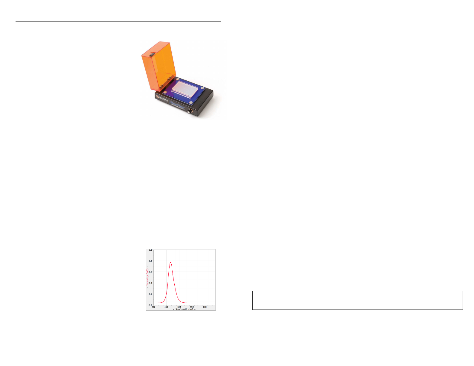
The Blue View Transilluminator is an
illuminating base for observing fluorescently
stained nucleic acid and protein gels. Using a
filtered bright blue LED light source, this
transilluminator excites stained gel bands
resulting in light emissions in the visible light
region of the spectrum.
Use the BlueView Transilluminator:
To visualize fluorescent bands from gel electrophoresis results.
To safely observe gel digest results.
As part of the Blue Digital Bioimaging System to photodocument and analyze
gel electrophoresis results.
To analyze transformation results using Green Fluorescent Protein (GFP).
What is Included with the BlueView Transilluminator?
BlueView Transilluminator
12 V AC Power Adapter
How to Use the BlueView Transilluminator
Connect the BlueView Transilluminator to AC power using the cable provided.
Note: Do not use any other power supply with the transilluminator. Lift the lid and
place the gel or tray holding the gel on the blue platform. Close the lid. Turn on the
unit by turning the knob and adjust the brightness for optimal viewing.
How the BlueView Transilluminator Works
The BlueView Transilluminator uses bright blue
LEDs and a blue filter to produce light with a peak
wavelength of 470 nm as shown in Figure 1. This
wavelength excites nucleic acids and proteins
stained with certain dyes, causing them to
fluoresce. The orange lid filters out the blue light
to reveal only the fluorescently stained bands.
A rotary dial control switch adjusts light intensity
to optimize visualization. A magnetic switch turns
off the LEDs when the lid is open.
Figure 1: Emission spectrum of
the BlueView Transilluminator
Which Stains Can Be Used with the BlueView Transilluminator?
Fluorescent stains and dyes that work well with the BlueView Transilluminator
include, but are not limited to, the following.
For nucleic acid gel electrophoresis:
SYBR
SYBR
SYBR
GelStar
®
Safe DNA Gel Stain
®
Green I DNA Gel Stain
®
Gold DNA Gel Stain
®
Nucleic Acid Gel Stain
GelGreen™ Nucleic Acid Gel
Stain
For protein gel electrophoresis:
®
SYPRO
Orange Protein Gel
Stain
SYPRO
®
Ruby Protein Gel
Stain
Coomassie Fluor™ Orange
Ethidium bromide
BlueView Transilluminator Specifications
AC power supply to external power brick: Input 0.8 A @ 100 to 240 V AC
DC power input to transilluminator: 2.0 A @ 12 V
Dimensions (excluding power supply): 17 cm 23 cm 10.5 cm
Care and Cleaning
For best results, keep the viewing surface as dry as possible. Should the lid or
viewing surface require cleaning, disconnect from power, use soapy water, and wipe
dry with a soft cloth to avoid scratching. Do not use solvents, glass cleaners,
cleansers, or any solution containing ammonia on these surfaces. If liquid wicks
under the blue viewing surface, disconnect power, unscrew and remove the four
Phillip’s screws, separate the white and blue plates, wipe dry with a soft cloth, and
reassemble before connecting power. If the lid fogs when viewing a gel, lift and
gently wipe with a soft cloth.
Patent Information
The BlueView Transilluminator includes Clare Chemical Research, Inc.'s
Dark Reader
more of Clare Chemical Research, Inc.'s U.S. Patent nos. 6,198,107,
6,512,236, and 6,914,250.
®
transilluminator technology and is covered by one or
Warranty
Vernier warrants the BlueView Transilluminator to be free from defects in materials
and workmanship for a period of five years from the date of shipment to the
customer. This warranty does not cover damage to the product caused by abuse or
improper use.
Note: This product is to be used for educational purposes only. It is not appropriate
for industrial, medical, research, or commercial applications.
2
Page 2
Blue Digital Bioimaging System
(Order Code BL-DBS)
The Blue Digital Bioimaging System is a
total system for illuminating, observing,
digitally photographing, and analyzing
fluorescently stained nucleic acid and protein
gels.
Use the Blue Digital Bioimaging System:
To view gel electrophoresis results.
To document and analyze gel
electrophoresis results using Logger Pro
software (Logger Pro sold separately.
See p. 7 for ordering information).
What is Included with the Blue Digital Bioimaging System?
BlueView Transilluminator
ProScope HR Body
1–10X ProScope Lens
ProScope Stand
Imaging Hood
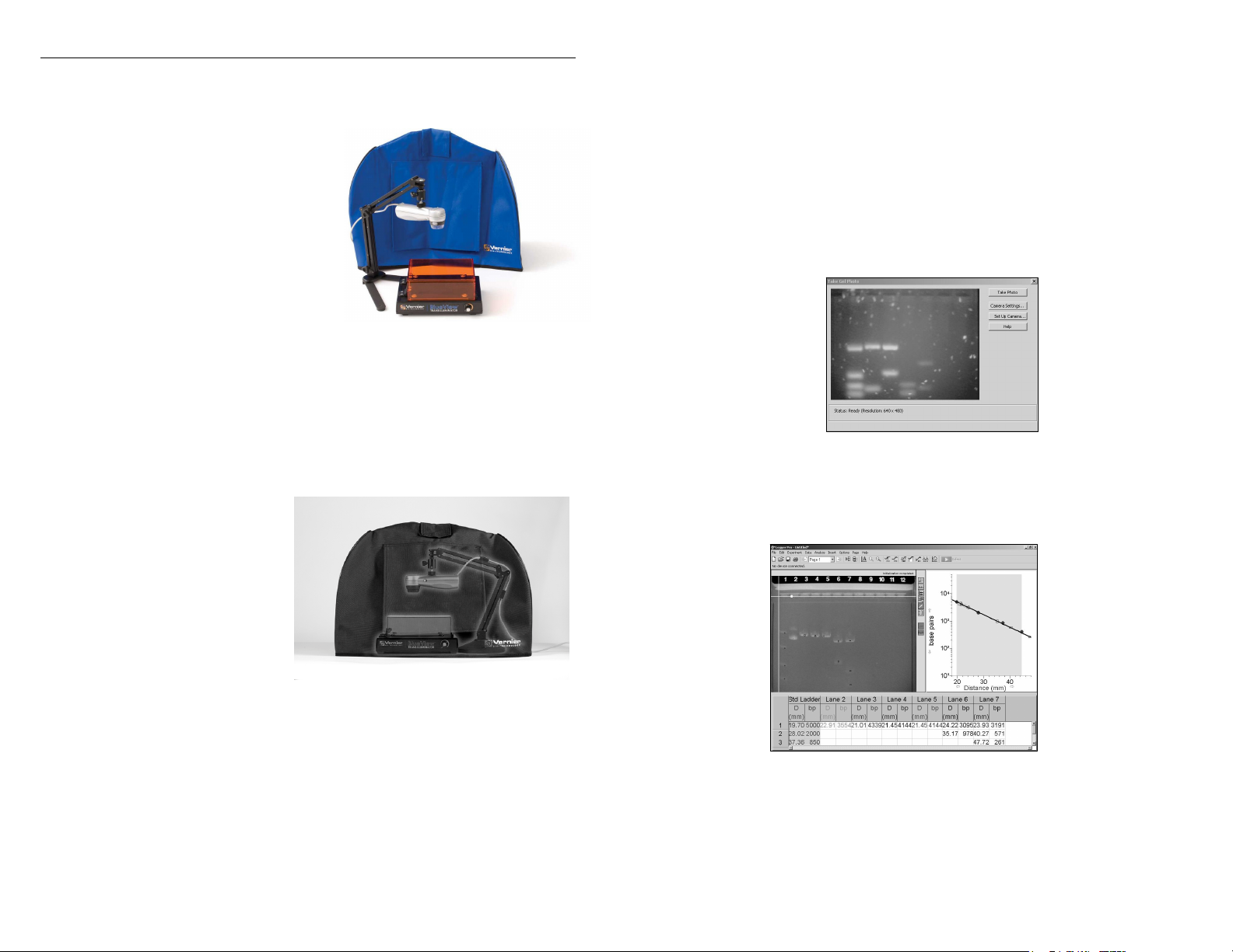
Setting Up the Blue Digital Bioimaging System
Place the gel in the BlueView
Transilluminator and adjust for
optimal viewing.
Assemble the ProScope, lens,
and Stand, and position above
the Transilluminator as shown
in Figure 2.
Place the Imaging Hood over
the entire apparatus.
Connect the ProScope USB
cable to the computer and
follow the documentation and
analysis sequence in the following
section.
Figure 2: Blue Digital
Bioimaging System
Method 1: Inserting a Digital Photo from File
1. Start Logger Pro.
2. Choose Gel Analysis from the Insert menu, then choose From File...
3. Choose the photo you want to analyze from your desktop folder.
4. Once the photo is on the screen, choose Auto Arrange from the Page menu.
Method 2: Taking a Digital Photo with a ProScope HR
1. Start Logger Pro.
2. Choose Gel Analysis from the Insert menu, then choose Take Photo. A dialog
box with a live picture from the ProScope, as shown in Figure 3, should appear.
Figure 3: Take Gel Photo
dialog box
3. When you are satisfied with the image, click the Take Photo button. Your screen
should now look similar to the one in Figure 4.
Obtaining a Digital Photo
There are two ways to obtain a digital photo for Gel Analysis in Logger Pro. In one
method, a photo is inserted into Logger Pro from an existing file on your computer.
In the second method, Logger Pro actively captures a photo of a gel using a digital
camera such as the ProScope HR.
3
Figure 4: Logger Pro ready to
begin Gel Analysis
4
Page 3

Gel Analysis in Logger Pro
The buttons along the right side of the photo will be used. The first four, shown
below, are the primary Gel Analysis tools. Holding the mouse over each button will
display its function. Text above the photo serves as a reminder of the next step in the
analysis.
Set Origin
Set Scale
Set Standard Ladder
Add Lane
4. Set Origin. In this step, you will show Logger Pro the position of the wells on
the photo.
Click the Set Origin button. Click on the photo just to the
left of the first well. A yellow coordinate system will appear
on the photo. The x-axis should go directly along the
bottom edge of the wells. You can move the origin by
grabbing either axis with the mouse and dragging it to the desired location.
The axes can be rotated by grabbing the round handle on the x-axis.
5. Set Scale. This optional step converts the units of distance measured from
number of pixels into millimeters or centimeters.
Click the Set Scale button. Drag the mouse between two
points of known distance apart. A window will appear
prompting you to enter this distance and its units. Note: If
your gel tray does not have a built-in ruler, you could measure either the
width or length of the gel tray and use as your reference. If no reference is
available, distances will be displayed in pixels, but base pair calculations
will be correct.
6. Set Standard Ladder. In this step, you will identify the bands of the standard
ladder and input their base pair values. Logger Pro will automatically create a
standard curve on the graph.
Click the Set Standard Ladder button. Click on the band
closest to the well of the standard ladder lane. Type the
corresponding number of base pairs into the field provided
in the resulting dialog box and click OK. Moving down this
lane, repeat these steps for each visible band of the standard ladder. Notice
the Standard Curve being created on the graph once you have added the
second point.
7. Add Lane. In this step, you will identity the experimental bands on the photo.
Logger Pro will then plot and calculate their respective number of base pairs
Click the Add Lane button and choose the Add Lane option.
Position the cursor over the leading edge of the band closest
to the well of the first experimental lane and click. Take a moment to notice
that when you click, three things happen: a marker with a distinct shape and
color was placed on the photo, a matching marker was placed on the graph,
and the distance and number of base pairs is added to the data table as
shown in Figure 3.
Continue in order down the lane, clicking on each of the remaining bands.
8. To analyze another lane, click on the Add Lane button again, choose Add Lane,
and repeat Step 7. Repeat this process for each experimental lane until the entire
gel has been analyzed, as shown in Figure 5.
Figure 5: Completed Gel Analysis
5
6
Page 4

Vernier Products for Biotechnology
Logger Pro Software (LP)
Blue Digital Bioimaging System (BL-DBS)
BlueView Transilluminator (BLUE-VIEW)
Imaging Hood (HOOD)
ProScope HR Body Only (BD-BODY)
1–10X Lens (BD-10X)
ProScope Stand (BD-STAND)
SpectroVis Plus Spectrophotometer (SVIS-PL)
Vernier UV-VIS Spectrophotometer (VSP-UV)
Additional Information
For more information on Vernier products for Biotechnology, please visit
www.vernier.com/biotech
Warranty
Vernier warrants this product to be free from defects in materials and workmanship
for a period of five years from the date of shipment to the customer. This warranty
does not cover damage to the product caused by abuse or improper use.
Vernier Software & Technology
13979 S.W. Millikan Way Beaverton, OR 97005-2886
Toll Free (888) 837-6437 (503) 277-2299 FAX (503) 277-2440
Rev. 11/5/2014
Logger Pro is our registered trademark in the United States. SYBR Safe and E-Gel containing SYBR Safe are provided
under license from Molecular Probes, Inc. All other marks not owned by us that appear herein are the property of their
respective owners, who may or may not be affiliated with, connected to, or sponsored by us.
Printed on recycled paper.
info@vernier.com www.vernier.com
7
8
 Loading...