

Page 1

Vortex+ Technical Manual
www.vernacare.com
NOV 2017
Page 2

Vernacare Vortex+ Technical Manual
Contents
Declaration of Conformity Page 01
Warranty Page 02
Section 1 - Specifications Page 05
Section 2 - Installation & Commissioning Page 08
Section 3 - General Description Page 15
Section 4 - Outer Casing Page 17
Section 5 - Motor Assembly Page 18
Section 6 - Diaphragm Valve Assembly Page 19
Section 7- Lid Arm Assembly Page 20
Section 8 - Top Cover Assembly Page 22
Section 9 - Hopper Vent Arrangement Page 23
Section 10 - Water Distribution Page 24
Section 11 - PCB Page 25
Section 12 - Electrical Enclosure Page 26
Section 13 - Sensor Terminal Page 26
Section 14 - Additional Items & Kits Page 26
Appendix A - Manual Pump and Outlet Buttons Page 28
Appendix B - Motor Terminal Wiring Page 29
Appendix C - Motor Electrical Box Plug & Socket Connectors Page 30
Appendix D - Orientation of Diodes for Solenoid Valve Coil Terminals Page 30
Appendix E - Suggested Periodic maintenance Page 31
Page 3

Page | 3
Declaration of Conformity
VERNACARE
Declare that this declaration has been issued under the sole
responsibility of the manufacturer. The object of the declaration is in conformity with the
relevant Union harmonisation
PRODUCT
Vernacare Vortex / Vortex + Macerator
DIRECTIVE
EC Directive 2014/30/EU
EC Directive 2006/42/EC
EC Directive 2014/35/EU
EC Directive 2002/95/EC (RoHS)
EC Directive 2011/65/EU (RoHS 2)
EC Directive 2002/96/EC (WEEE)
STANDARDS
IEC EN61010 - 1: 2001
BS EN61010-1: 2001
BS EN 61000-6-1:2005
BS EN 61000-6-3:2007
Conformity is demonstrated by the affixing of the CE Mark.
LOCATION
Vernacare Limited
Folds Road
Bolton
Lancashire
United Kingdom
BL1 2TX
DATED
23/05/2016
AUTHORISING SIGNATURE
C.E.O of Vernacare Limited
Page 4

Page | 4
Warranty
A. Warranty terms
1. The warranty is for 12 months from the date of commissioning or 18 months from the
date of delivery, whichever is the shortest period.
2. The warranty will cover parts and labour.
3. The warranty will not cover customer damage or abuse.
4. Warranty requests should be submitted in writing, quoting the machine number, date
of commissioning and the machine fault.
5. The warranty will not affect your statutory rights, or rights given in the company’s
Terms and Conditions of Sale.
6. Extended warranties are available. Contact Vernacare for further details.
B. Conditions of warranty
1. The Vortex+ must be installed to the instructions provided in this technical manual.
2. The Vortex+ must be commissioned by a person authorised by Vernacare,
failure to do so may invalidate the warranty.
3. Unauthorised modifications may invalidate the warranty if not carried out by
a person authorised by Vernacare.
The above warranty details should be read in conjunction with the Company Terms
and Conditions of Sale, copies of which are included with your invoice, or available
upon request from Vernacare:
Telephone: +44(0)1204 555988 Fax: +44(0)1204 523595
E-mail: [email protected]
C. Service Contracts
To ensure continued reliability and performance, service contracts are available.
All warranty and service contract work will be carried out by Vernacare Technical
Services, a division of Vernacare Limited OR in the case of an overseas installation,
warranty and service contract work will be carried out by a Vernacare approved
technician.
Page 5

Page | 5
1
Specifications
1.1 Capacities and usage
The “Vernacare Vortex +” macerator will dispose of a maximum of four “Vernacare”
disposable products such as bedpan liners, bottles etc. together with their contents in a
single cycle. Please note due to their physical size only two Vernacare wash bowls
may be disposed of per cycle.
Products should be placed in the Vortex + one at a time and should not be stacked inside
each other.
Do not stack products inside each other or attempt to dispose of more than four items
in a single cycle as this will impair the effective operation of the machine and in severe
cases, may cause the motor to stall. It is considered good practice to operate the
machine each time a utensil is placed into the machine.
Do not place string, wipes, plastic or metal items inside the machine as these may
damage components.
Note: Vernacare “Senset” wipes can be disposed of in the Vortex macerator.
1.2 Dimensions
The dimensions of the “Vernacare Vortex +” are shown on page 9 (Figure 1)
1.3 Handling
The weight of the “Vernacare Vortex +” complete with pallet and packaging is 83 kg
(machine only 72 kg). The “Vernacare Vortex +” should be moved to the point of
installation by fork, pallet or sack truck whilst still attached to the pallet provided.
1.4 Electrical specification
The machine is supplied with a 3-meter length of 1.5mm flex, which shall be connected
to either:
230 Volt Machine – 16 Amp MCB to BS EN60898 Type C or alternatively fused 16 Amp
to BS EN60269-1. An appropriate I.E.C Approved 16 Amp isolator shall be installed in
both cases.
110 Volt Machine – 16 Amp MCB to BS EN60898 Type C or alternatively fused 16 Amp
to BS EN60269-1. An appropriate I.E.C Approved 16 Amp isolator shall be installed in
both cases.
It is recommended that the disposal unit is supplied by a dedicated circuit.
Where supplementary protection is provided by an RCD/RCBO, this should be rated at
100mA.
Note: The machine should not be switched off at the mains supply in mid-cycle
Page 6

Page | 6
except in case of emergency, as this will impair the effective operation of the
machine and may cause damage to the components.
1.4.1 Motor
1.1 KW; 3 Phase; 220-240v 50Hz/ 380-420v 50Hz; IP55; D90 frame size. Rating at
peak load 4.57 amps (nominal).
1.4.2 Invertor
AC invertor with either 110v or 230v supply voltage, 230v motor output and utilising
current monitoring.
1.4.3 Pump
0.27 kW; 24vdc; 50 cycles. 40 l/min at 5 lbs/in². Protected by a 5 amp fuse.
1.5 Water requirements
Inlet supply: Cold water ONLY with flow rate of 18 l/min (4 gals/min) nominal. Nominal
overall usage; 25 litres (+/- 10%) per cycle.
1.6 Drainage
A 2 inch/ 50mm P Trap compression fitting to be connected either directly, or via a swept
bend, to a standard 2in/50mm drain pipe with a 1 in 25 or suitable fall into a soil drain.
A 1 1/4 inch/32mm tank connector is supplied, which should be used to connect the
water tank warning pipe to a separate drain line, according to the relevant water
regulations.
A standard warning pipe installation kit is available. Contact Vernacare Customer Care
Department for details.
Page 7
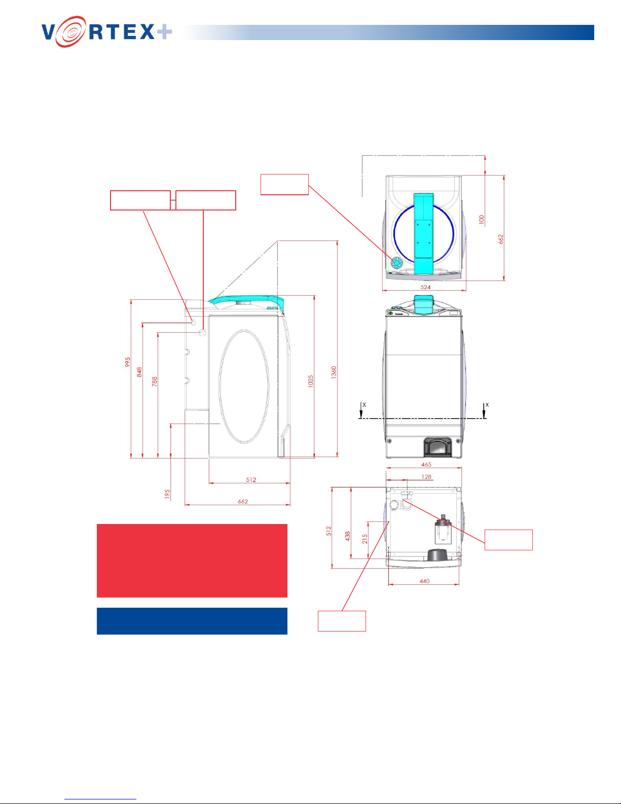
Page | 7
150mm Clear each side
100mm Clear at rear
Deodoriser
fill cap
NOTE:
Water inlet & warning pipe
connections can be made to
either the left or right hand side
of the machine.
2" Drain
Connector
ALL DIMENSIONS IN mm
2 Mounting
Holes Ø9
Dimensions of the Vernacare Vortex +
Water Inlet
½’’ BSP Male
Warning Pipe
Connection
(drain)
with lid open !IMPORTAN
T!
Page 8

Page | 8
2 Installation / Commissioning
Installation
Note: Installation of this equipment should only be carried out by a suitable
qualified person.
2.1 Siting and fixing
The “Vernacare Vortex +” disposal unit should be positioned adjacent to the following:
a) A suitable power supply point.*
b) An adequate water supply line.
c) A suitable drainage connection.
Check the floor area is firm and level. The unit must be bolted down using the holes
provided. Mark out the bolt positions on the floor and fit bolts utilizing the
dimensions given in Figure 1.
Ensure that adequate space is maintained at each side of the Macerator to
allow for access. Vernacare recommend a gap of 6” - 8” (150 - 200mm) per side and 4”
- 5” (100 - 125mm) away from the wall at the back.
Important- To comply with UK WRAS regulations sufficient clearance must be provided
to allow water to freely discharge from the water tank overflow weir.
Check that the unit is level in both directions.
230 Volt Machine – 16 Amp MCB to BS EN60898 Type C or alternatively fused 16 Amp
to I.E.C 60269-4. An appropriate I.E.C Approved 16 Amp isolator shall be installed in
both cases.
110 Volt Machine – 16 Amp MCB to BS EN60898 Type C or alternatively fused 16 Amp
to I.E.C 60269-4. An appropriate I.E.C Approved 16 Amp isolator shall be installed in
both cases.
Where supplementary protection is provided by an RCD/RCBO, this should be rated at
100mA.
For all installations, an I.E.E. approved disconnection device must be fitted to the
final installation. This device shall be positioned in close proximity to the Vortex and
within easy reach of the operator & shall also be clearly marked as being the
disconnecting device for the machine.
For installations where the height of the existing drain causes difficulty a plinth is
available which may be utilised in order to raise the height of the Vortex so that
better alignment is achieved.
Please contact Vernacare for further information
Page 9

Page | 9
2.2 Plumbing
2.2.1 Water supply
The machine should be connected to a suitable cold water supply as follows:-
The connection to the machine water tank is made at the upper rear left or right hand
side corner of the machine. It is a standard connection to a 1/2 inch BSP float-type
cistern valve. This can be made in rigid or flexible piping, according to customer
preference. Flow rate should be 18 litres per minute (4 gallons/minute) minimum, into
the water tank, which holds sufficient water for a complete cycle.
Note: The inlet flow valve is supplied already fitted with a flow restrictor in place. The
restrictor should be left in place on tank fed installations with heads above 50ft or mains
fed installations with pressures above 1.5 bar (25psi). In all other circumstances the flow
restrictor is not required.
2.2.2 Drain connection
The “Vernacare Vortex +” is fitted with a 2 inch/50mm ‘P’ Trap. In order to connect to the
drain, it is necessary to cut a minimal clearance hole in the plastic drain access cover
located at the rear of the machine below the water tank. It is important to ensure that the
drain access cover is fitted so as to prevent access to internal electrical components.
The drain is secured by tightening the compression fitting on the ‘P’ Trap onto the
inserted plastic pipe. The free area below the water tank allows for the fitting of a swept
bend if required.
Page 10

Page | 10
2.2.3 Overflow - Warning Pipe
The Vortex Is supplied with a 32mm (1 ¼“) tank connector which should be installed
using one of the predrilled holes in either the Left Hand side or Right Hand side of the
water tank. It is Important that any discharge from the warning pipe is visible.
A standard warning pipe installation kit is available. Contact Vernacare Customer Care
Department for details.
Points to Watch
Ensure that the supply line to the unit is at no point less than 15mm or larger is available
head is low.
Ensure that the water supply cannot be starved by any other fittings.
Fit an easily accessible, full way isolating valve close to the unit.
For installations with dirty water supplies it is recommended that an in-line filter is fitted.
Ensure that the route taken to soil drain is the shortest, with minimum number of bends. If
necessary, use long radius or ‘swept’ bends - never short or 90’ elbows.
The waste must be run separately to the soil stack or drain.
Ensure that there is a fall of a minimum of 1 in 25 or a sufficient fall to maintain a self-
cleansing velocity.
Provide easy access for Roding.
Ensure a clean run inside the pipework - leave no burrs or reducing shoulders.
With plastic pipework, ensure that there is no reduction in the bore size and that there is
adequate support for horizontal runs to prevent sagging. Remember, ceiling voids can get
very warm.
Avoid running the drain line near or across hot water pipes.
Anti-syphon precautions should be in line with general practice.
Ensure that the discharge from the warning pipe is visible.
Warning pipe arrangement must include an air break prior to a connection to a drain.
Waste must be run separately to soil stack or drain.
Do not reduce the diameter of the warning pipe at any point.
Page 11

Page | 11
2.3 Electrical
2.3.1 Single-phase electrical system (230v, 1 Ph, 50 HZ) (110v, 1 ph, 60 HZ)
The machine is supplied with a 3 metre length of 1.5mm flex to BS6500 which
shall be connected to:
• 230 Volt Machine – 16 Amp MCB to BS EN60898 Type C or fused 16 Amp to
IEC 60269.
• 110 Volt Machine – 16 Amp MCB to BS EN60898 Type C or fused 16 Amp to
IEC 60269.
Notes:
1. All electrical installation to comply with current I.E.E. regulations.
2. Mains supplies to be protected by:
1 Phase 230v ......... 16 Amp approved I.E.C. fuse.
1 Phase 110v…….. 16 Amp approved I.E.C. fuse.
3. For all installations, an I.E.E. approved disconnection device must be fitted to the
final installation. This device shall be positioned in close proximity to the Vortex and
within easy reach of the operator & shall also be clearly marked as being the
disconnecting device for the machine.
Page 12

Page | 12
2.3.2 Back-up generator tests / mains electrical supply surges.
Damage to internal electrical components of the Vortex macerator can occur as a result
of voltage surges / spikes occurring in the electrical supply to the machine. The likelihood
of such damage occurring is increased when frequent testing of back-up electrical
supplies are carried out.
To prevent such damage, Vernacare recommends that transient voltage suppressors (in
accordance with IEC class 3 surge protection) be installed in the electrical supply to the
machine.
2.4 Environment
Indoor use only. Altitudes up to 2000m. Temperatures 5C to 40C.
Maximum relative humidity 80% for temperatures up to 31C, decreasing linearly to 50%
relative humidity at 40C.
Mains supply voltage fluctuations not to exceed +/- 10% of nominal voltage.
2.5 Commissioning
After installation, to ensure warranty validity the machine should be commissioned by a
Vernacare technician OR in the case of an overseas installation, by a Vernacare
approved technician. The machine should not be run until after this check has been
done.
Important
The machine MUST be bolted down before use. The machine should be run once
- empty - to prime the pipework, diaphragm valve, deodoriser feed etc.
Note: For warranty, service or repair please quote the machine serial number which can
be found clearly marked upon the rating plate which is positioned on the RH side, bottom
front of the machine.
2.6 Warning labels and icons – explanations
Please refer to the technical manual prior to installation, maintenance
or operation of this equipment.
Symbol indicates presence of 230v 50hz/ 415v 3phase 50hz electrical
supply.
Start Cycle – Press this button to start the machine. An auto-start option is also
available. Contact Vernacare for more information.
Page 13
Page | 13
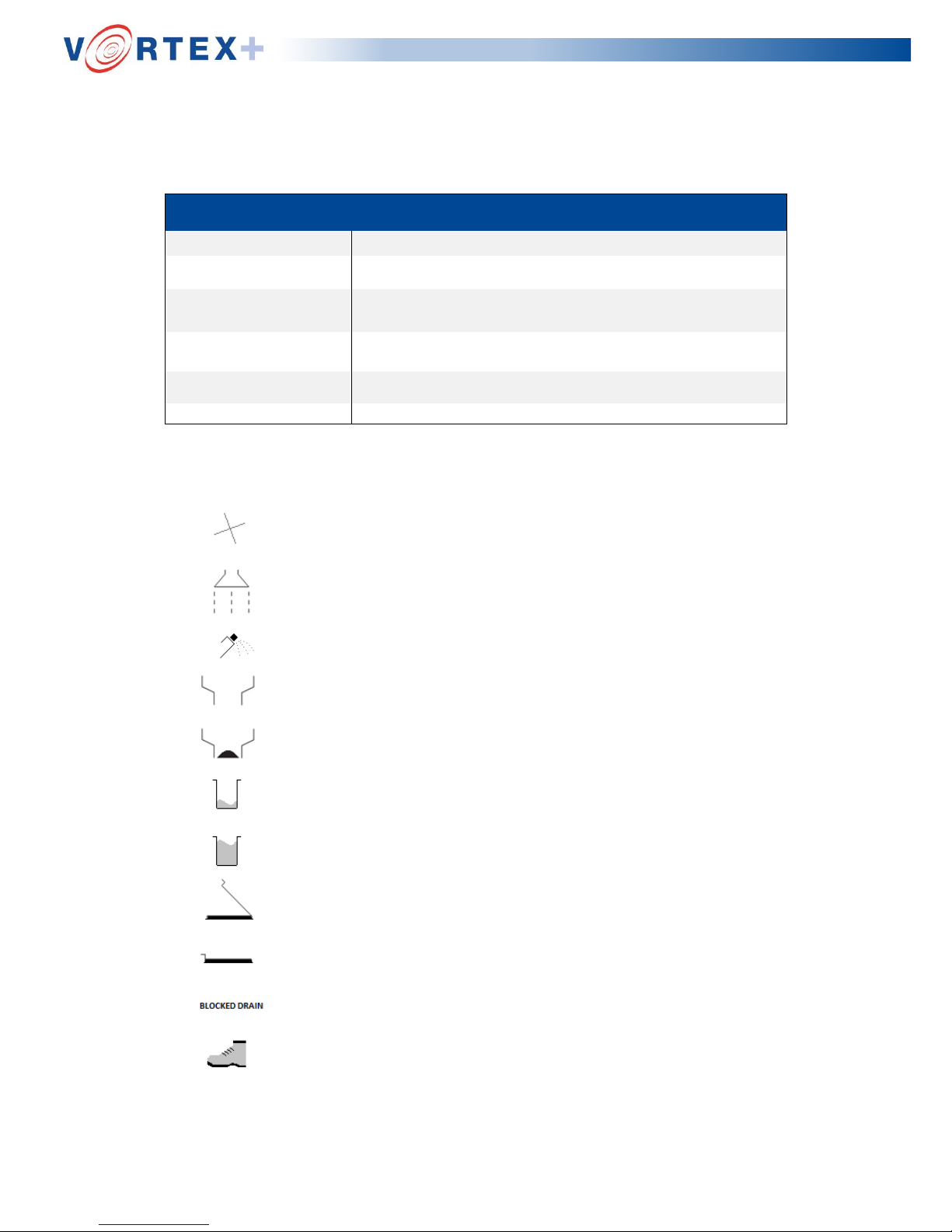
2.7 Display screen icons and warning messages –
explanations
ERROR
DESCRIPTION
RUNNING
The machine has been started and is running through its cycle.
END
The machine has finished the cycle and is ready to open.
BLOCKED BLADES
The motor invertor has defaulted to overload due to a blockage of the
machine cutter blades.
BLOCKED DRAIN
The pressure transducer has sensed an over pressure in the chamber
due to a blockage of the drain outlet.
LOW WATER
There is insufficient water in the water supply tank.
POWER FAIL
There has been an interruption to the mains power supply/cycle.
The motor is running and the cutter blades are rotating.
The water pump is running.
The deodoriser reservoir is empty.
The outlet diaphragm is open.
The outlet diaphragm is closed.
The water tank reservoir level is low.
The water tank reservoir is full.
The lid is open.
The lid is closed.
The drain is blocked.
The foot sensor has been operated.
(For details of the fault finding guide see section 14 page 29).
Page 14

Page | 14
2.7.1 Cycle Counter
At the end of each cycle the LCD screen will briefly display the TOTAL cycle count for
the machine and also the SERVICE count which is the number of cycles since the
machine was last serviced.
The TOTAL cycle display counts every machine cycle and is not resettable (unless the
machine is reprogramed).
The SERVICE count is reset by the engineer when the machine is serviced. The
service count will also trigger a “Service” message on the LCD display once 20,000
cycles have been completed since the last service visit.
Page 15

Page | 15
3 General Description
3.1 General description
The “Vernacare Vortex +” disposal unit is designed to operate within a 2-minute cycle
using 24 litres +/-10% of water. The machine can dispose of up to four ‘Vernacare”
disposable single- use products, at one time.
Disposable single-use products are placed within the hopper. Activation of the foot
sensor causes the lid to descend and lock when in the fully closed position. The lid is
closed against a moulded silicone section which gives an effective seal whilst
maintaining an abrasion resistant face.
Sensors in the lid actuator and lid lock ensure that the lid is fully closed & physically
locked. Failure or loss of signal from either sensor will prevent / stop the cycle. Once the
lid is fully closed and locked the cycle is initiated automatically, at which point the
machine will give an ‘audible sound’ and the cycle will commence
The display screen will then indicate the machine is ‘Running’ and the icons at the
bottom of the screen will show the status of operation. (See section 2.7)
In the event of low water level, blocked blades or power failure, the fault will be clearly
indicated upon the display screen and the cycle stopped. The Vortex+ will remain in this
condition until the fault is cleared by following the instructions on the display screen.
The 2-minute cycle is controlled by a microprocessor, which controls the operation and
timing of the water pump, the cutter motor and the inlet, outlet and deodoriser solenoid
valves.
Shortly after commencement of the cycle, the water pump starts to take water
from the reservoir tank and pumps it to the following areas:
a) The lid spray, which provides a curtain of water, which washes over the lid and tub
sides and provides the bulk of the ‘tub fill’ water.
b) The mechanical seal flush, which flushes and lubricates the faces of the
mechanical seal to prevent ingress of pulp fibres into the mechanical seal cavity.
c) The drain diaphragm valve, where water is fed through the non-return and inlet
solenoid valve to the back of the drain diaphragm valve, water outlet is shut off by the
normally closed outlet solenoid valve, thus developing pressure expands the drain
diaphragm valve to form a seal.
The combined water from a, b and c above enters the tub whilst the pump runs for a
pre-set time period to put 12 litres (+/- 10%) of water into the tub.
When the outlet valve has closed and the volume of water is building up in the tub, the
displaced air is vented away through the drain via the vent valve and non-return valve
arrangement, i.e. the non-return valve prevents the egress of foul air from within the tub
into the atmosphere.
With the pump switched off, the diaphragm valve remains sealed as the water behind
It is restrained by the non-return and solenoid valves.
During the period when the pump is running, the cutter motor starts up via the inverter unit,
and breaks up the products by a combined mechanical and hydraulic action into
Page 16
Page | 16
small particles which can be easily flushed down the drain.
If the cutter motor is initially stalled by bottles blocking the blades, the invertor will reverse
the blades and attempt to cut through the blockage again. This will be attempted three
times before a ‘Blocked Blade’ fault is displayed. At which point the lid is to be opened
and the blockage removed.
Approximately three-quarters of the way through the cycle the pump restarts to give a
dilution flush of an additional 12 litres (+/- 10%) to the tub and its contents.
At the same time the inlet solenoid valve closes thus preventing additional pumped water
from reaching the drain diaphragm, as the inlet solenoid valve is closed and the outlet
solenoid valve opens which allows the pressurised water behind the drain diaphragm valve
to dissipate. This allows the drain diaphragm to open and the contents of the tub to run to
the drain.
During this period, the motor will initiate for a few brief seconds. This will dissipate any
pulp particles from the blades and allow them to be washed to the drain.
Also at this point the deodoriser valve is opened and a small quantity of deodoriser is
dispensed from the storage reservoir into the chamber removing any odours that may be
present. In the event of the deodoriser reservoir being empty, the cycle will continue but
the icon on the display will indicate the tank is empty and requires re-filling.
Vernacare recommend the use of Vernacare Vortex+ disposal unit deodoriser
(902DL1000, 902DL2000, 902SD1000, 902SD2000).
The water pump then stops, the outlet solenoid valve closes a second later and then the
overall cycle program ends. The display will indicate `End`.
The Vortex+ will remain in this condition with the lid locked until the foot sensor is
operated. When the infra red beam is broken by the insertion of the operator’s foot into
the foot well at the bottom front of the machine, the lid lock disengages and the lid
actuator opens the lid.
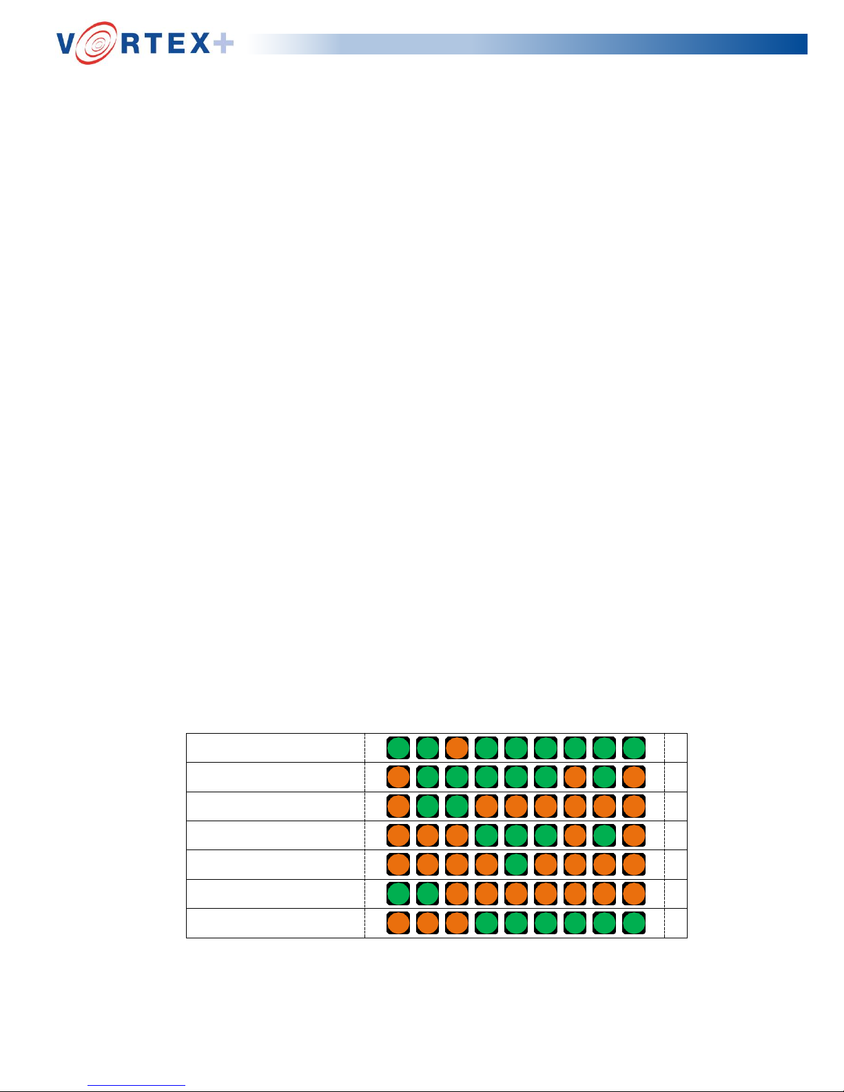
Vortex+ Normal Cycle Sequence
Pump
ON ON OFF ON ON ON ON ON ON
Motor Forward
OFF ON ON ON ON ON OFF ON OFF
Motor Speed 1 (55Hz)
OFF ON ON OFF OFF OFF OFF OFF OFF
Motor Speed 2 (66Hz)
OFF OFF OFF ON ON ON OFF ON OFF
Deodoriser Valve
OFF OFF OFF OFF ON OFF OFF OFF OFF
Inlet Solenoid
ON ON OFF OFF OFF OFF OFF OFF OFF
Outlet Solenoid
OFF OFF OFF ON ON ON ON ON ON
Cy
cle
E
nd
Step
9
(120
s
)
Step
8
(114
s
)
Step
7
(105
s
)
Step
6
(104
s
)
Step
5
(103
s
)
Step
4
(9
4
s)
Step
3
(4
6
s)
Step
2
(1
7
s)
Step
1
(
2
s
)
St
ar
t
Cy
cle
Page 17
Page | 17
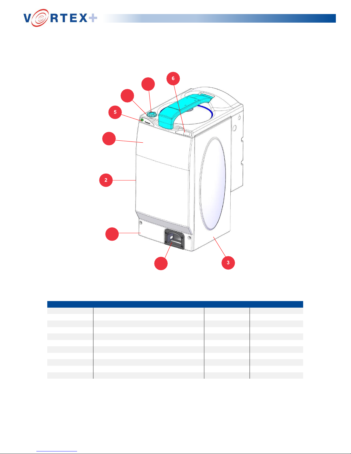
SECTION 4: Outer Casing
KIT
REF
PART DESCRIPTION
KIT NUMBER
ITEM NUMBER
1
Front Cover Kit
9207014
1.1
Front Cover
9200531
1.2
Foot Sensor Housing
9200531
1.3
M6 x 20 Panel Screw (x2)
9750023
2
2
RH Side Panel
9200610
3
3
LH Side Panel
9200611
4
Deodoriser Cap Kit
9207013
4.1
Deodoriser Tank Cap
9200206
4.2
Filler Cap ‘O’ Ring
9200209
5
5
Start Switch Keypad
9200534
6
6
Display Screen
9200819
4.1
4.2
1.1
1.3
1.2
Page 18
Page | 18
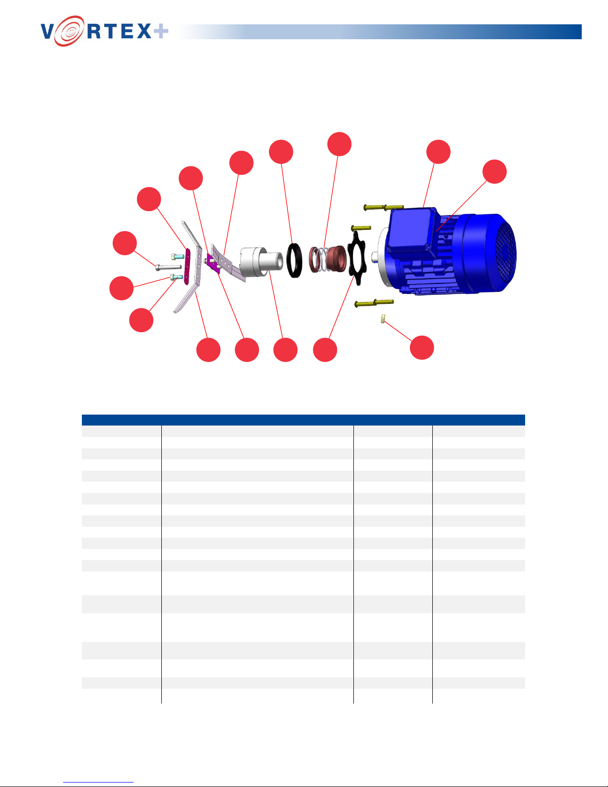
SECTION 5: Cutter & Motor
1.1
1.4
1.3
1.21.53.43.1
3.8
3.6
3.5
3.3
3.7
3.2
2.2
1.6
KIT
REF
PART DESCRIPTION
KIT NUMBER
ITEM NUMBER
1
Vortex Motor Kit
9207004
1.1
Electric Motor 230V/400V 3Ph 50Hz
9200424
1.2
Motor Gasket
9752027
1.3
Barbed Fitting
9750100
1.4
Vortex Motor Cable
9200693
1.5
Cutter Motor Adaptor
9200402
1.6
Mechanical Seal
9753005
2
Vortex Mechanical Seal Kit
9207006
(1.6)
Mechanical Seal
9753005
2.2
V-Seal 9753000
3
Vortex Blade Kit
9207015
3.1
Top Cutter Blade
9200418
3.2
Bottom Cutter Blade
9200417
3.3
Cutting Blade Locking Plate (Tab
Washer)
9753011
3.4
M8 x 20 Hex HD Screw x2
9750077
3.5
M8 x 50 Hex HD Screw x1
9750006
3.6
M8 x 35 Button HD Screw x2
9750075
3.7
Fibre Gasket
9753010
3.8
D8 Spring Washer x2
9750033
4
Cutter Motor Assembly Kit
9207005
Page 19
Page | 19
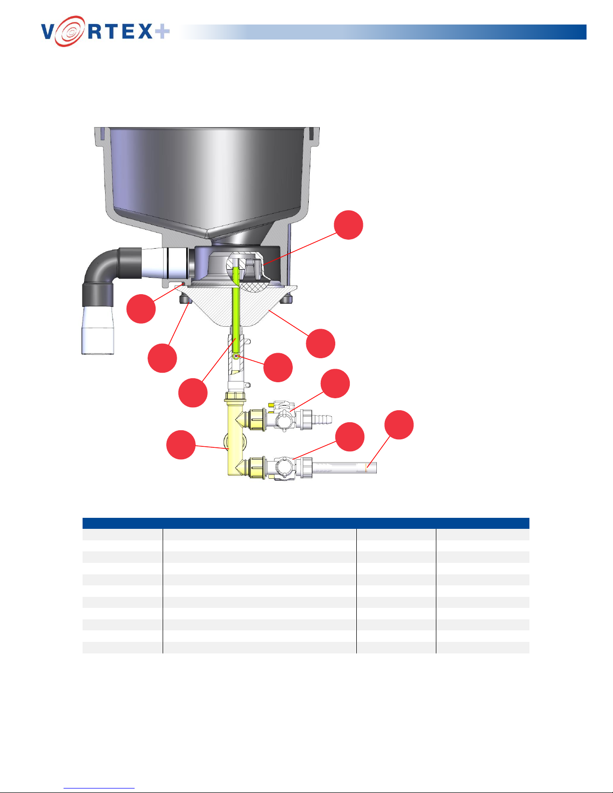
SECTION 6: Diaphragm Valve
1.1
5
3
4
3
6
1.3
1.2
2.2
2.1
KIT
REF
PART DESCRIPTION
KIT NUMBER
ITEM NUMBER
1
Diaphragm & Spring Kit
9207012
1.1
Diaphragm
9200304
1.2
Diaphragm Spring
9200333
1.3
Retaining Pin
9750085
2
Diaphragm Fastening Kit
9207016
2.1
Grub Screw x 8
9200326
2.2
Three Lobed Nut x 8
9200327
3
3
Water Inlet/Outlet Solenoid Valves
9200724
4
4
Non Return Valve
9200726
5
5
Diaphragm Chassis
9200328
6
6
Plumbing Elbow
9207043
Page 20
Page | 20
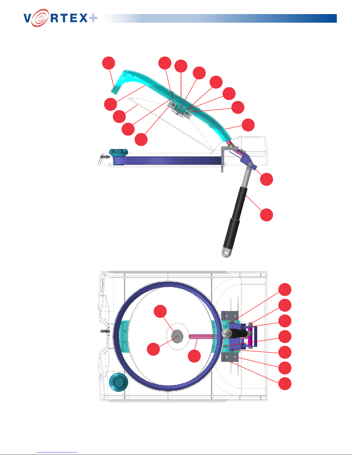
SECTION 7: Lid Arm Assembly
1.1
1.2
1.3
1.4
1.5
1.6
1.7
1.8
1.9
1.10
1.11
1.12
1.13
1.14
1.15
1.16
1.17
1.18
1.19
1.20
1.20
1.22
1.23
1.24
Page 21
Page | 21
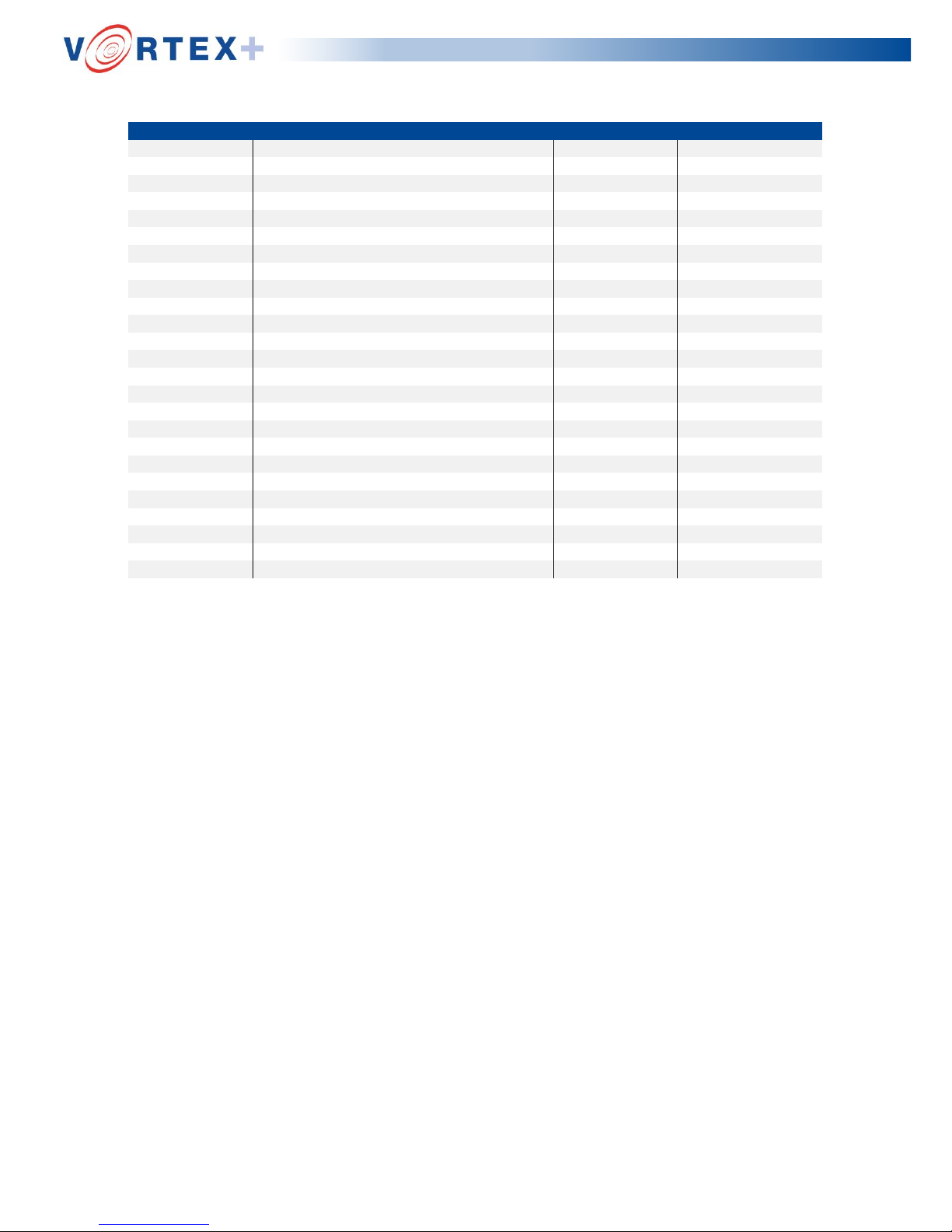
KIT
REF
PART DESCRIPTION
KIT NUMBER
ITEM NUMBER
1
Lid Arm Assembly Kit
9207034
1.1
Lid Arm Bottom
9200843
1.2
Lid Arm Top
9200842
1.3
Lid 9200103
1.4
Extension Bracket
9200932
1.5
Arm Seal
9200853
1.6
Lid to Arm Seal
9200109
1.7
Hinge Bush (x2)
9200146
1.8
Press Lok Insert
9200115
1.9
Lid Spray Washer
9200117
1.10
Self-Tapping Screw (x2)
9200120
1.11
Lid Spacer Short (x2)
9200122
1.12
Lid Spacer Long (x2)
9200856
1.13
M5 Nyloc Nut (x4)
9750012
1.14
Arm Inlet Pipe
9200162
1.15
D8 Spring Washer
9750033
1.16
D5 Plain Washer (x4)
9750011
1.17
Lid Arm Label
9200860
1.18
Arm Hinge Shaft (x2)
9200113
1.19
Hinge Block (x2)
9200114
1.20
M10 Aero Nut (x2)
9200865
1.21
M10 Plain Washer (x4)
9200866
1.22
Torx Head Self-Tapping Screws (12)
9200924
1.23
Linear Actuator
9200854
1.24
Neodymium Magnet
9200837
Page 22
Page | 22
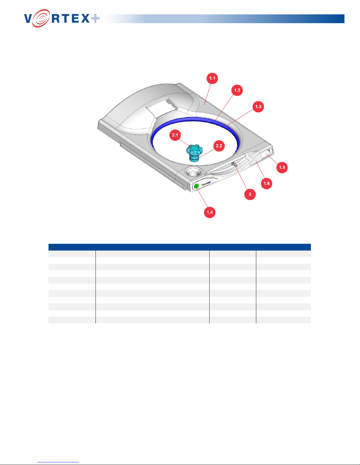
SECTION 8: Top Cover
KIT
REF
PART DESCRIPTION
KIT NUMBER
ITEM NUMBER
1
Top Cover Assembly Kit
9207035
1.1
Top Cover
9200841
1.2
Lid Seal 9200159
1.3
Lid Seal Clip
9200152
1.4
Start Switch Keypad
9200534
1.5
Display Screen
9200819
1.6
Display Membrane
9200535
2
Deodoriser Cap Kit
9707013
2.1
Deodoriser Tank Cap
9200206
2.2
Filler Cap ‘O’ Ring
9200209
3
3
Sriker Bolt Kit
9200847
Page 23
Page | 23
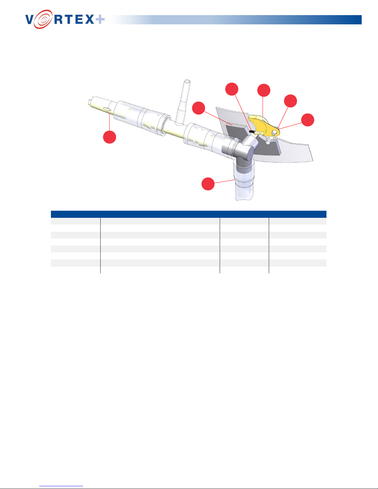
SECTION 9: Hopper Vent Arrangement
1.1
2
1.2
1.3
1.4
1.5
1.6
KIT
REF
PART DESCRIPTION
KIT NUMBER
ITEM NUMBER
1
Vent Connector Kit
9207007
1.1
Non Return Valve
9757030
1.2
Vent Connector
9200334
1.3
‘O’ Ring 9752018
1.4
Vent Deflector
9200325
1.5
M4 x 8 Lg Slotted Pan Head Screw (x2)
9750064
1.6
M4 Nylon Washer x2
9752022
2
2
16mm PVC Tubing 1.5m
9200721
Detail of Vent Connection
Situated at the front top right hand side of the hopper is a vent connector (2) which allows
the foul air which is displaced whilst water is filling the hopper, to be vented into the
drain.
The vent connector is fitted with a non - return valve (push fit into connector with the
arrow on its body pointing into the connector). This valve prevents air from being
expelled to atmosphere during water filling but allows air to be drawn into the hopper
during the drain cycle when a vacuum would otherwise be created.
The connector is secured to the hopper via two M4 screws and two nylon washers, to
prevent leakage an O-ring is used to seal the connector to the hopper and is located in
a groove on the inner face of the connector
Page 24
Page | 24
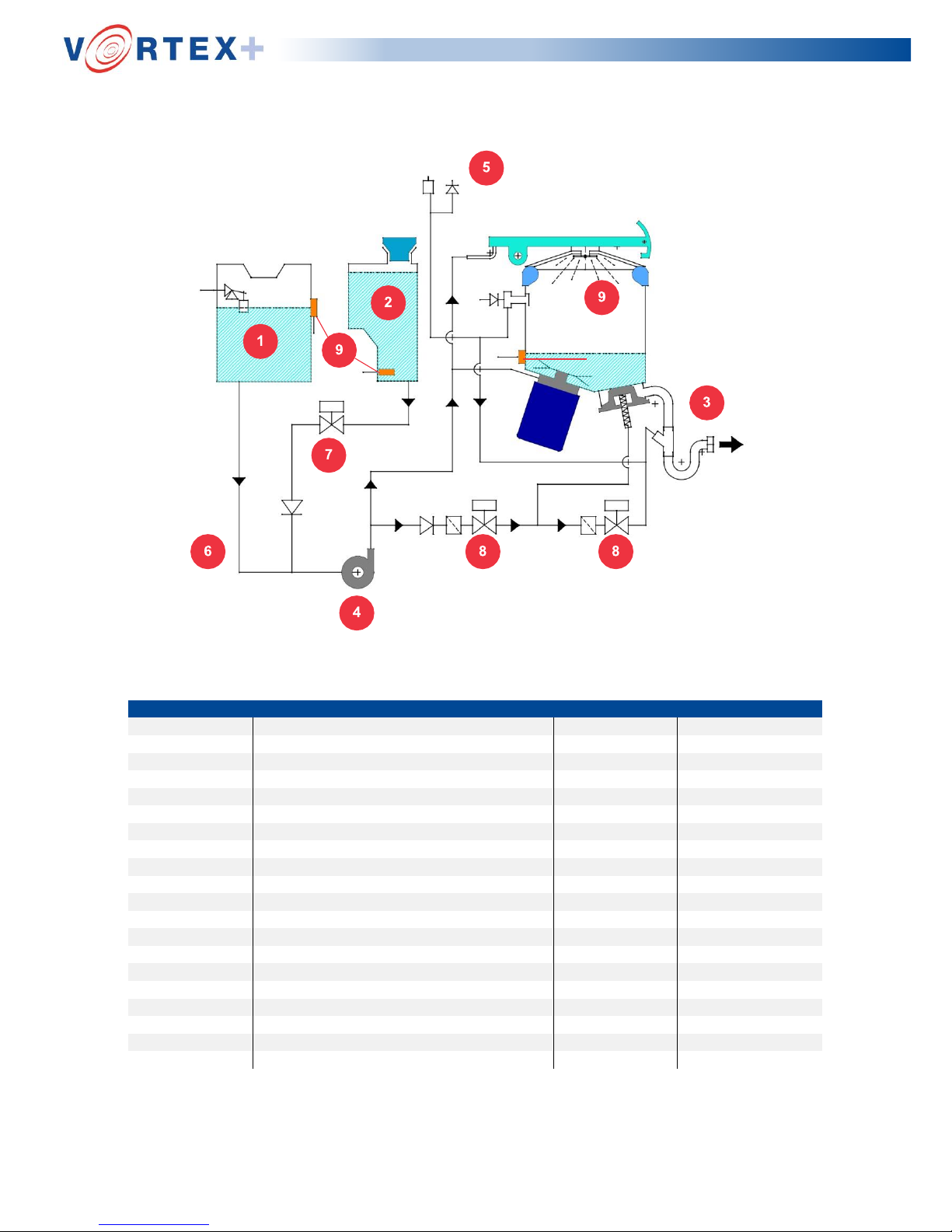
SECTION 10: Water Distribution
KIT
REF
PART DESCRIPTION
KIT NUMBER
ITEM NUMBER
1
1
Water Tank Assembly Kit
9207010
N/A
End Caps (x2)
9757047
N/A
Blank Plug
9757034
N/A
Hydroflo Side Entry Float Valve
9200204
N/A
Water Tank
9200846
N/A
No.6 x ½ Pozi Screw Button Head
9200212
N/A
Float Valve Bracket
9200211
N/A
M4 Plain Washers
9200540
2
2
Deodoriser Tank Kit
9207009 N/A
Deodoriser Tank
9200207
3
3
2’’ P trap Kit
9207008
N/A
Hose Clips 60mm
9757035
N/A
Drain Connector
9757001
N/A
2’’ P Trap
9757002
4
4
Water Pump
9200529
5
5
Anti-Syphon Valve
9200875
6
6
Pump Inlet Assembly
9200728
7
7
Deodoriser Solenoid Valve
9200725
8
8
Water Inlet/outlet Solenoid
9200724
9
9
Capacitive Sensors
9200828
Page 25
Page | 25
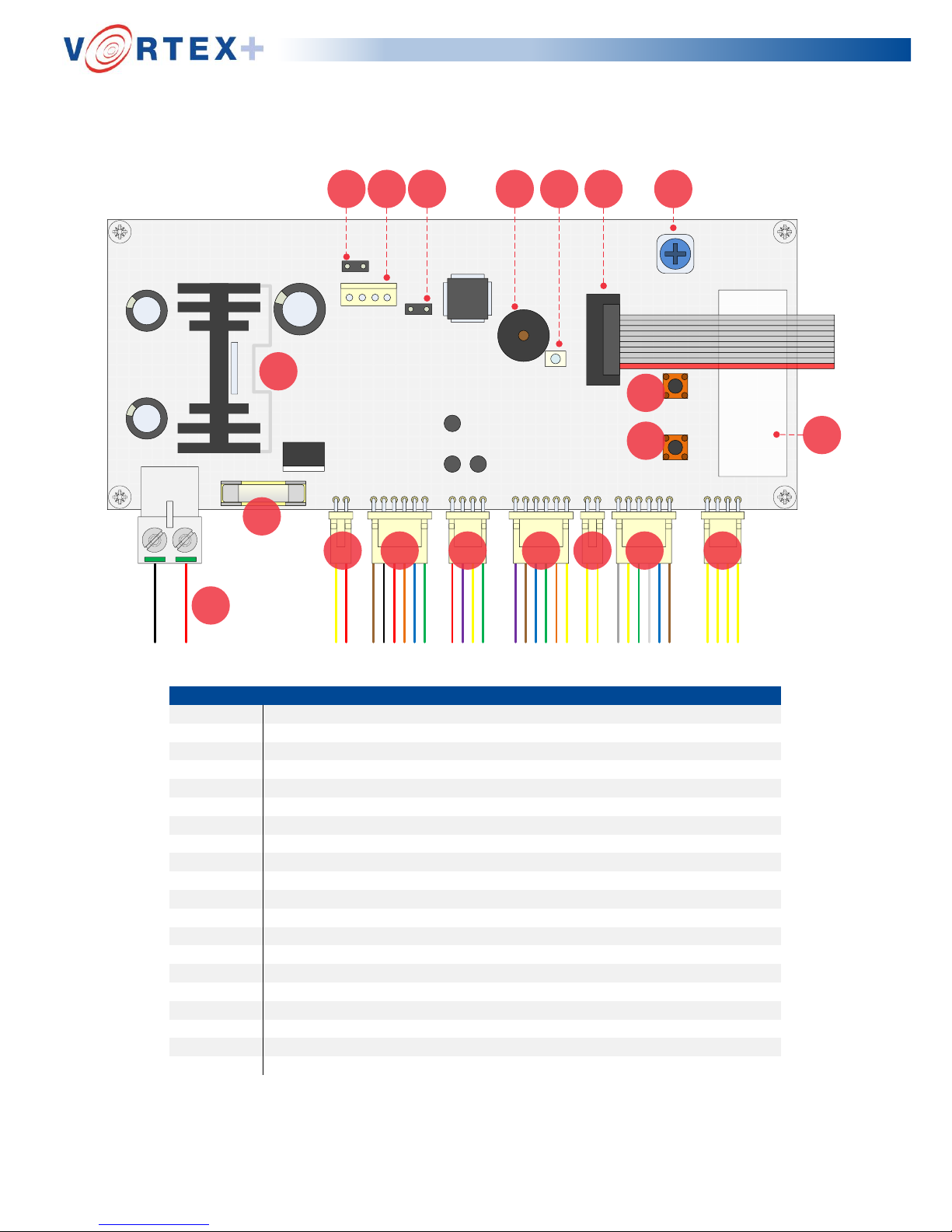
SECTION 11: PCB
Vortex + V2
Outlet
Pump
2 3 4 5 6 7 8
1
9 10 11 12 13 14 15
16
18
19
17
20
REF
1
2
3
4
5
6
7
8
9
10
11
12
13
14
15
16
17
18
19
20
DESCRIPTION
24v PCB Power Supply Cable Connection
Actuator Board Cable Connection
Lid-Lock Cable Connection
Solenoid Valve(s) Cable Connection
Data Cable Connection
Start Button Cable Connection
IFM Sensor Cable Connection
Pressure Transducer Cable Connection
Auto-Start Jumper Plug Connection
Software Fob Cable Connection
Service (Cycle Count Reset) Cable Connection
Audible Buzzer
Pulsing LED PCB Indicator
E-Paper Display Ribbon Cable Connection
Pressure Switch Potentiometer
Manual Pump Button
Manual Outlet button
5A Fuse
5V Voltage Regulator & Heat Sink
Serial Number Marking Area
Page 26
Page | 26
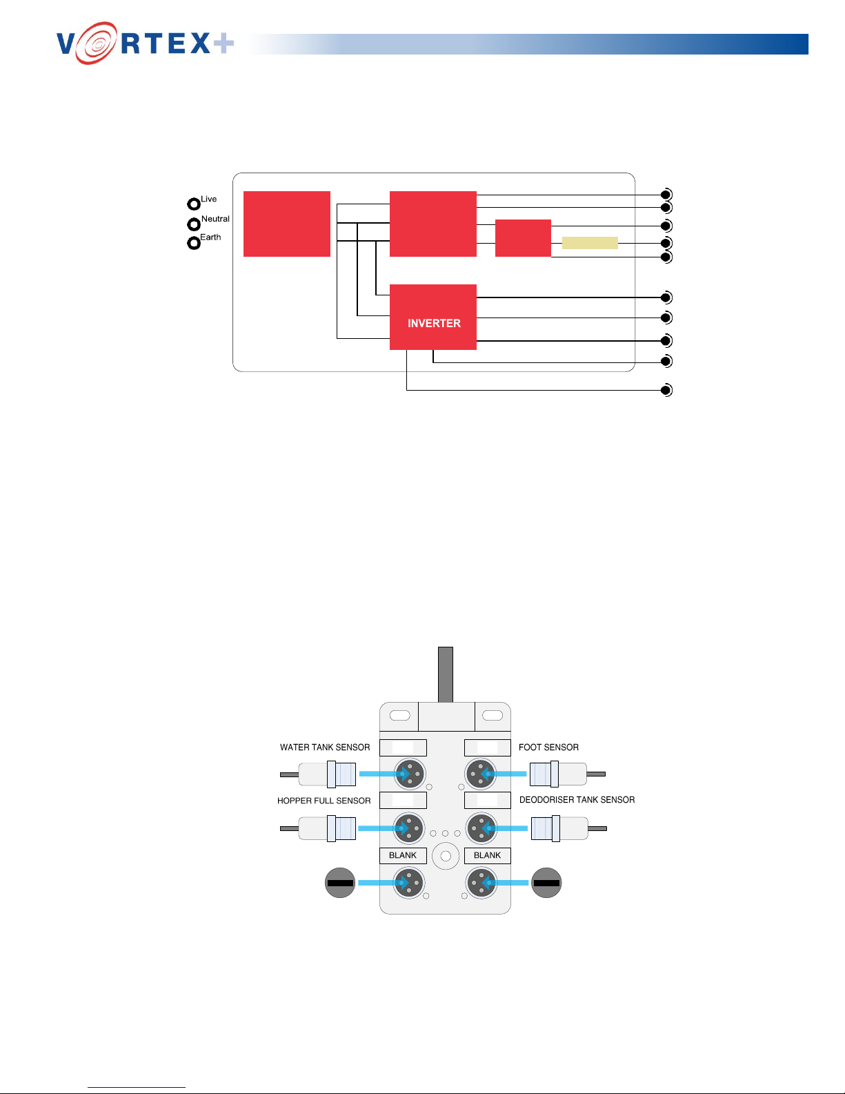
SECTION 12: Electrical Enclosure
Mains
Supply
(210-240V
OR 110V)
PCB 24V Supply
PCB Signal
24V Water Pump
3-
Phase Moto
220V (Delta)
24V PCB
Signal Wires
Lid Sensor
Safety Switch
SECTION 13: Sensor Terminal
Detail of Sensor Terminal
The terminal is located on the underside of the motor support plate. It acts as a hub to
connect 4 sensors to the PCB via M12 jumper plugs. There are 6 connection points on
the terminal, 2 of which are not used and are blanked off. The correct orientation of the
jumper cables is as below.
2 1
4 3
Electrical Enclosure
24V
RELAY
5A
EMC FILTER
POWER
SUPPLY
MOTOR
Page 27

Page | 27
SECTION 14: Additional Items & Kits
PART DESCRIPTION
KIT NUMBER
ITEM NUMBER
Vortex + PCB
9200838
Water Pump
9200529
Power Supply Unit 230V (UK)
9200940
E-Paper Display Screen
9200819
Start Switch Keypad
9200534
Electronic Rotary Latch
9200869
Power Supply Unit 110V (Outside UK)
9200941
Vortex + Actuator Controller
9200855
Solenoid Diode kit
9207019
Water & Disinfectant Cable Kit
9207020
PCB Power Cable Kit
9207022 Water Pump Diode Cable Kit
9207023
Installation Kit
9207025
Vortex + Program Fob
9200750
E-Paper Display Kit ( includes display, PCB &
pressure switch )
9207033
Page 28

Page | 28
Appendix A
Engineer’s manual pump and outlet pushbuttons
Sited on the face of the PCB within the main electrical panel are two manual
push buttons. The first button is the drain outlet valve manual opening. The
second button is the pump manual run. The button locations are shown to
the right of the Vortex PCB Image below.
In the event of the machine being in failure mode during the cycle, often the
tub will be still full of water and or product due to the drain outlet being closed.
Operating the manual outlet pushbutton will open the drain outlet diaphragm
and allow the contents to empty into the main drain. Additionally the water
pump can be run manually to help with the drainage.
If the water tank is full during a cycle when in fault condition, the tank can be
drained to allow work to be carried out on the water system. Firstly the water
tank has to be isolated from the water supply to stop the water tank from re
filling. The manual `pump` pushbutton can then be pressed, this will pump
out any water from the tank and out in to the main drain.
Maintenance can then be carried out on the pipe system with only a minimum
of water left. Both push buttons are identified in the PCB section (12).
Do not run the pump dry, as this will result in damage to the pump
seals.
Page 29
Page | 29
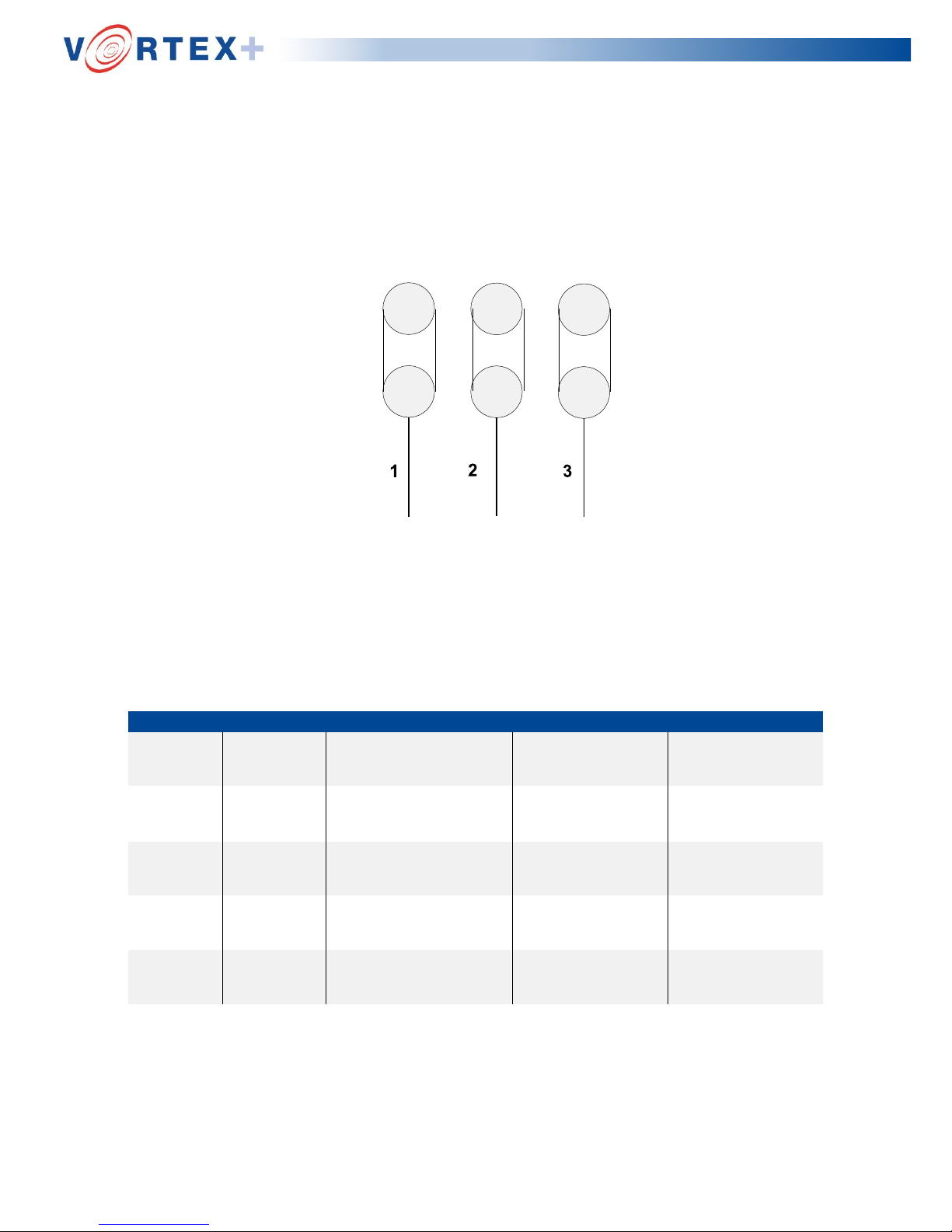
Appendix B
Diagram for Motor Terminal Wiring
Motor wired in Delta for 220 volt input from the invertor unit.
W2 U2
V2
U1 V1
W1
Ø Ø Ø
Voltage amps check for Vortex Macerator.
Note: Readings are for a product load of four bottles.
VOLTAGE
PHASE
NOM RUNNING LOAD
MAX LOAD
MAX PEAK
110 1 2.5 to 4.8 amp
6.1 to 12.7 amp
44 amp
200 1 2.9 to 3.5 amp
6.3 to 8.8 amp
39 amp
220 1 2.8 to 3.2 amp
5.3 to 9.1 amp
41 amp
230 1 2.4 to 3.1 amp
5.2 to 8.1 amp
44 amp
250 1 2.8 to 3.7 amp
5.3 to 7.9 amp
44 amp
Page 30
Page | 30
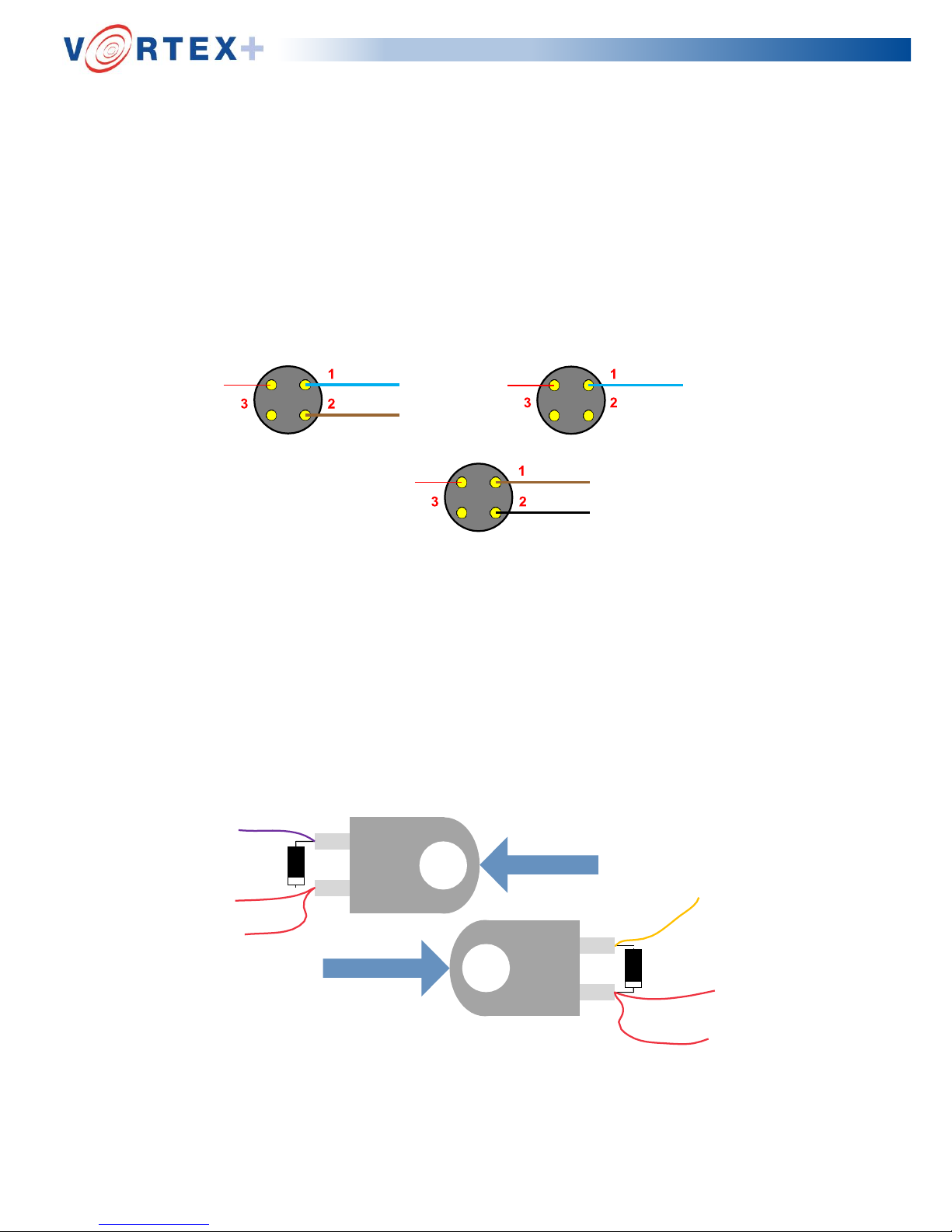
Appendix C
Diagram for motor electrical box plug and socket connections
Power Supply 230V
AC socket/plug
Power Supply 110V
AC socket/plug
Appendix D
Motor socket/plug
Orientation of Diodes for drain inlet and drain outlet solenoid
valve coil terminals
Diode
OUTLET VALVE
INLET VALVE
Diode
Page 31

Page | 31
Appendix E
A Suggested periodic planned maintenance
1 Remove all panels (clean as required, see cleaning instructions below).
2 Clean the lid seal & check for wear or damage.
3 Check that the lid arm lock operates effectively via the foot operation.
4 Check the blade for damage and free rotation.
5 Check the condition and correct positioning of the V- seal on cutter adapter (ensure lip
is in constant contact with hopper bottom). Vortex+ must be electrically isolated whilst
carrying out this operation.
6 Operate the machine - when pump stops (after approx. 30 sec) isolate the machine from
power, open lid and check for correct water level in hopper (observe for approx. 5-10
seconds). Correct water level is level with the top of the hopper base +/- 12 mm.
7 Check the condition of the diaphragm valve, its seating and operation.
8 Check the non-return valve’s operation, clean if required. i.e. if the water level is low
within the hopper.
9 Check the solenoid valve’s operation, clean if required. i.e. if the water level is low in
the hopper.
10 Check all plumbing, pipe work and connections for leaks.
11 Check that the solenoid valve filters are clean.
12 Check for water at the seal flush pipe during the cycle and that the pipe is not blocked.
13 Check the operation of the tub vent assembly and small non-return valve.
14 Check the drain and overflow connections for leaks.
15 Check the operation of the water inlet float valve.
16 Check the operation of the deodoriser level switch.
17 Check the operation of the water-level switch (clean if required).
18 Remove and clean the external in-line filter (if fitted).
19 Check the drain pressure sensing unit operates correctly.
20 Check that the foot sensors are working correctly and operating the lid.
21 Check the connections to all electrical components.
22 Replace all panels.
23 Check the deodoriser tank level. Fill if necessary with Vernacare disposal unit
deodoriser part number 203MD005
24 Run a full load test cycle.
B Cleaning Instructions
Wipe down external surfaces using Tuffie 5 wipes, Tuffie detergent wipes or detergent
and water as required. Internal components can be kept clean by running a daily
cleansing cycle (without product).
 Loading...