

Vermont Castings VWDV70NTSCSB Installation And Operating Instructions Manual
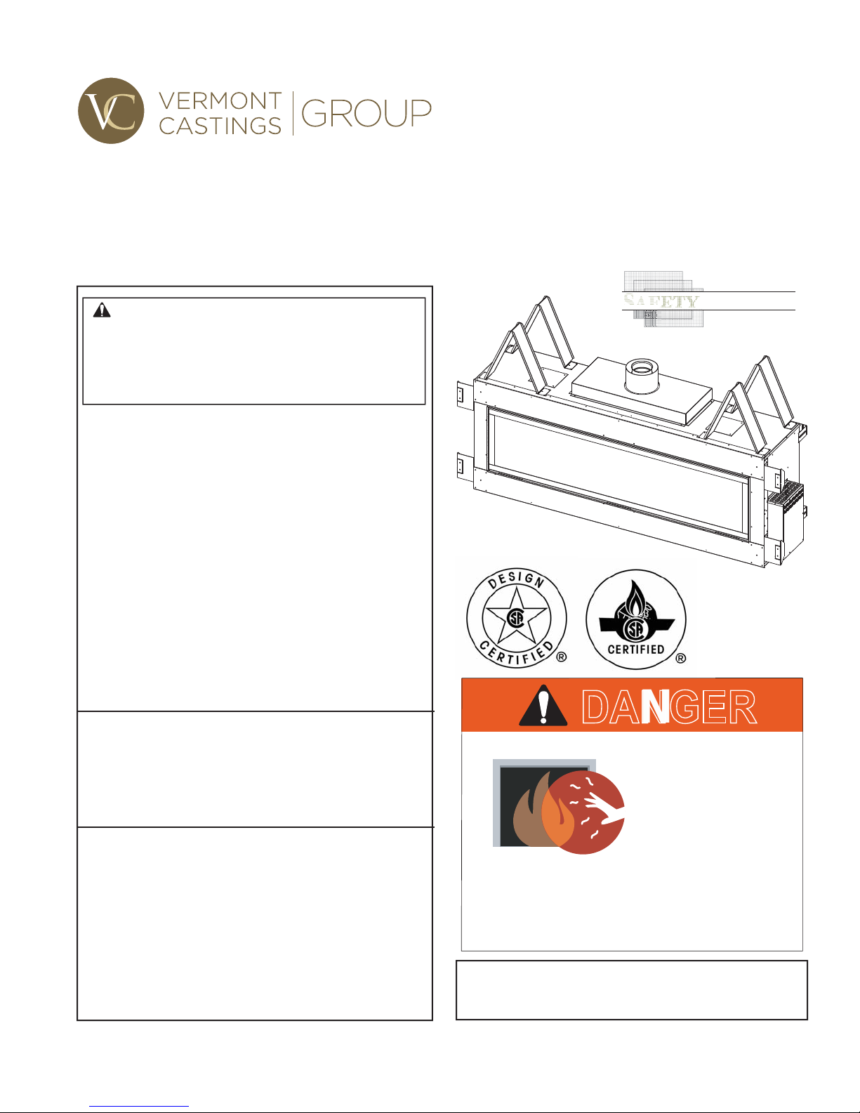
VWDV70NTSCSB Direct Vent Gas Fireplace
Installation and Operating Instructions
WARNING:
FIRE OR EXPLOSION HAZARD
Failure to follow safety warnings exactly
could result in serious injury, death or
property damage.
• Do not store or use gasoline or other
fl ammable vapors and liquids in the
vicinity of this or any other appliance.
• WHAT TO DO IF YOU SMELL GAS
– Do not try to light any appliance.
– Do not touch any electrical switch; do
not use any phone in your building.
– Leave the buildling immediately.
– Immediately call your gas supplier from
a neighbor's phone. Follow the gas
supplier's instructions.
– If you cannot reach your gas supplier,
call the fi re department.
• Installation and service must be performed
by a qualifi ed installer, service agency or
the gas supplier.
WARNING: Improper installation, adjustment,
alteration, service or maintenance can cause
injury or property damage. Refer to this manual.
For assistance or additional information consult
a qualified installer, service agency or the
gas supplier.
This appliance may be installed in an aftermarket,*
permanently located, manufactured home (USA
only) or mobile home, where not prohibited by
local codes.
This appliance is for use only with the type of gas
indicated on the rating plate. This appliance is
not convertible for use with other gases, unless
a certifi ed kit is used.
* Aftermarket: Completion of sale, not for purpose of resale, from
the manufacturer.
CERTIFIED
SAFETY BARRIER
DANGER
HOT GLASS WILL
CAUSE BURNS.
DO NOT TOUCH GLASS
UNTIL COOLED.
NEVER ALLOW CHILDREN
TO TOUCH GLASS.
A barrier designed to reduce the risk of burns from the hot
viewing glass is provided with this appliance and shall
be installed for the protection of children and
other at risk individuals.
20306543
INSTALLER: Leave this manual with the appliance.
CONSUMER: Retain this manual for
future reference.
20306745 12/14 Rev. 1

VWDV70 Series Gas Fireplace
CONTENTS
Thank you and congratulations on your purchase of a
Vermont Castings Group Fireplace.
PLEASE READ THE INSTALLATION AND OPERATION INSTRUCTIONS BEFORE USING THE APPLIANCE!
IMPORTANT: Read all instructions and warnings carefully before starting installation.
Failure to follow these instructions may result in a possible fi re hazard and will void the warranty.
Important Safety Information ......................................3
Code Approval ......................................................... 4
Product Features ..........................................................5
Product Specifi cations ............................................. 5
High Elevations ........................................................ 5
Gas Pressures ......................................................... 5
Gas Specifi cations & Orifi ce Size ............................ 5
Before You Start ....................................................... 5
Firebox Framing ....................................................... 5
Fireplace & Framing Dimensions................................6
Pre-Installation Information .........................................7
Fireplace Location .................................................... 7
Cold Climate Insulation ............................................ 7
Clearances ....................................................................8
Clearances to Combustibles .................................... 8
Secure Fireplace to Floor or Framing.........................9
Finishing Material ..................................................... 9
Noncombustible Requirements ................................10
Noncombustible Facing Installation ....................... 10
Venting Installation .....................................................12
Installation Precautions .......................................... 12
Installation Planning ............................................... 13
For Horizontal Termination ..................................... 13
For Vertical Termination ......................................... 13
Installing a Vent System in an Outside Chase ....... 13
General Venting – Termination Location ................ 14
Termination Clearances ......................................... 15
How to Use the Vent Graph ................................... 15
Vertical Sidewall Installation ................................... 16
Vertical/Horizontal Termination Confi gurations ...... 17
Below Grade Installation ........................................ 18
Vertical Through-the-Roof Applications ................. 19
Installation for Vertical Termination ........................ 20
Termination Heights for Vents above Flat or
Sloped Roofs ......................................................... 21
Flex Vent Installation .................................................. 22
Fireplace Installation ..................................................24
Check Gas Type..................................................... 24
Install Gas Piping to Fireplace/Burner System ...... 24
Check Gas Pressure .............................................. 26
Electrical Installation..................................................27
Electrical Wiring ..................................................... 27
Junction Box Wiring ............................................... 27
Command Center Wall Installation ......................... 27
Signature Command® System Wiring Diagram ..... 28
Final Installation ......................................................... 29
Glass Frame Removal ........................................... 29
Bulb Replacement .................................................. 29
Porcelain Panels .................................................... 29
Glass & Stone Placement ...................................... 30
Accessory Log Installation ..................................... 31
Safety Barrier Installation Instructions ................... 32
Signature Command® System Operating
Instructions .......................................................... 35
For Your Safety Read Before Lighting ................... 35
Operating Instructions ............................................ 36
To Turn Off Gas to Appliance ................................. 36
Features ................................................................. 37
Battery Installation ................................................. 37
System Confi guration/Setup .................................. 38
Cold Climate Option ............................................... 38
Functions/Operation ............................................... 39
Command Center Operations ................................ 39
Self Diagnostics Chart ........................................... 39
Touch Screen Remote Control Operation ................ 40
Fuel Conversion .........................................................46
Conversion Instructions ......................................... 46
Testing and Burner Assembly ................................ 48
Cleaning and Maintenance ........................................ 49
Burner, Pilot and Control Compartment ................. 49
Pilot Flame ............................................................. 49
Burner .................................................................... 49
Burner Flame ......................................................... 49
Vent System ........................................................... 50
Glass Door ............................................................. 50
Stones .................................................................... 50
Troubleshooting .........................................................51
Signature Command® System ............................... 51
Replacement Parts ..................................................... 52
Firebox Components and Accessories .................. 52
Signature Command System and Engine .............. 53
Glass ...................................................................... 55
Stones .................................................................... 55
Venting Components ..................................................56
Vent Components for 5"x*8" Pipe .......................... 56
Massachusetts Residents Only.................................58
Limited Lifetime Warranty .........................................59
Effi ciencies.................................................. Back Cover
2
20306745
IMPORTANT SAFETY INFORMATION
VWDV70 Series Gas Fireplace
INSTALLER
Please leave these instructions with the appliance.
OWNER
Please retain these instructions for future reference
WARNING
• Read this owner’s manual carefully and completely before trying to assemble, operate, or service this
fi replace.
• Any change to this fi replace or its controls can be dangerous.
• Improper installation or use of this fi replace can cause serious injury or death from fi re, burns, explosions,
electrical shock and carbon monoxide poisoning.
This fi replace is a vented product. This fi replace must be
properly installed by a qualifi ed service person. The glass
door must be properly seated and sealed. If this unit is not
properly installed by a qualifi ed service person with glass
door properly seated and sealed, combustion leakage
can occur.
CARBON MONOXIDE POISONING: Early signs of carbon
monoxide poisoning are similar to the fl u with headaches,
dizziness and/or nausea. If you have these signs, the fi re-
place may not have been installed properly. Get fresh air
at once! Have the fi replace inspected and serviced by a
qualifi ed service person. Some people are more affected
by carbon monoxide than others. These include pregnant
women, people with heart or lung disease or anemia, those
under the infl uence of alcohol, and those at high altitudes.
Propane/LP gas and natural gas are both odorless. An
odor-making agent is added to each of these gases. The
odor helps you detect a gas leak. However, the odor added
to these gases can fade. Gas may be present even though
no odor exists.
Make certain you read and understand all warnings. Keep
this manual for reference. It is your guide to safe and proper
operation of this fi replace.
1. This appliance is only for use with the type of gas
indicated on the rating plate. This appliance is not
convertible for use with other gases unless a certifi ed
kit is used.
2. For propane/LP fi replace, do not place propane/LP
supply tank(s) inside any structure. Locate propane/
LP supply tank(s) outdoors. To prevent performance
problems, do not use propane/LP fuel tank of less than
100 lbs. capacity.
3. If you smell gas
• shut off gas supply.
• do not try to light any appliance.
• do not touch any electrical switch; do not use any
phone in your building .
• immediately call your gas supplier from a neigh-
bor’s phone. Follow the gas supplier’s instructions.
4. Never install the fi replace
• where curtains, furniture, clothing, or other fl am-
mable objects are less than 42" from the front, top,
or sides of the fi replace
• in high traffi c areas
• in windy or drafty areas
5. This fi replace reaches high temperatures. Keep chil-
dren and adults away from hot surfaces to avoid burns
or clothing ignition. Fireplace will remain hot for a time
after shutdown. Allow surfaces to cool before touching.
6. Carefully supervise young children when they are in
the room with fi replace.
7. Do not modify fi replace under any circumstances. Any
parts removed for servicing must be replaced prior to
operating fi replace.
8. Turn fi replace off and let cool before servicing, install-
ing, or repairing. Only a qualifi ed service person should
install, service, or repair the fi replace. Have burner
system inspected annually by a qualified service
person.
9. You must keep control compartments, burners, and
circulating air passages clean. More frequent cleaning
may be needed due to excessive lint and dust. Turn off
the gas valve and pilot light before cleaning fi replace.
10. Have venting system inspected annually by a qualifi ed service person. If needed, have venting system
cleaned or repaired. Refer to Cleaning and Mainte-
nance, Page 42.
11. Keep the area around your fi replace clear of combus-
tible materials, gasoline, and other fl ammable vapor
and liquids. Do not run fi replace where these are used
or stored. Do not place items such as clothing or decorations on or around fi replace.
12. Do not use this fi replace to cook food or burn paper or
other objects.
13. Never place anything on top of fi replace.
14. Do not use any solid fuels (wood, coal, paper, cardboard, etc.) in this fi replace. Use only the gas type
indicated on rating plate.
• in a recreational vehicle
.
20306745
3
VWDV70 Series Gas Fireplace
IMPORTANT SAFETY INFORMATION
15. This appliance, when installed, must be electrically
grounded in accordance with local codes or in the
absence of local codes, with the National Electrical
Code, ANSI/NFP A 70, or the Canadian Electrical Code,
CSA C22.1.
16. Do not obstruct the fl ow of combustion and ventilation
air in any way. Provide adequate clearances around air
openings into the combustion chamber along with adequate accessibility clearance for servicing and proper
operation.
17. When the appliance is installed directly on carpeting, tile
or other combustible material other than wood fl ooring,
you must set appliance on a metal or wood panel or
hearth pad extending the full width and depth of the
appliance.
18. Do not use fi replace if any part has been exposed to
or has been under water. Immediately call a qualifi ed
service technician to inspect the appliance and replace
any part of the control system and any gas control which
as been submerged in water.
19. Do not operate fi replace if any log is broken.
20. Do not use a blower insert, heat exchanger insert, or
any other accessory not approved for use with this
fi replace.
21. Do not operate the fi replace with glass door removed,
cracked, or broken.
IMPORTANT:
PLEASE READ THE FOLLOWING
CAREFULLY
It is normal for fi replaces fabricated of steel
to give off some expansion and/or contraction
noises during the start up or cool down cycle.
Similar noises are found with your furnace heat
exchanger or car engine.
IMPORTANT:
PLEASE READ THE FOLLOWING
CAREFULLY
It is not unusual for gas fi replace to give off
some odor the fi rst time it is burned. This is due
to the manufacturing process.
Please ensure that your room is well
ventilated during burn off — open all
windows.
It is recommended that you burn your fi replace
for at least ten (10) hours the fi rst time you use
it. Place the fan switch in the “OFF” position
during this time.
Never connect unit to private (non-utility)
gas wells. This gas is commonly known
as wellhead gas.
WARNING
CODE APPROV AL
Direct Vent type appliances draw all combustion air from
outside of the dwelling through the vent pipe.
These appliances have been tested by CSA and found to
comply with the established standards for DIRECT VENT
GAS FIREPLACE HEATERS in the USA and Canada as
follows:
LISTED VENTED GAS FIREPLACE HEATER
TESTED TO:
ANSI Z21.88-2009 / CSA 2.33-2009 STANDARDS
A manufactured home (USA only) or mobile home OEM
installation must conform with the Manufactured Home
Construction and Safety Standard, Title 24 CFR, Part
3280, or when such a standard is not applicable, the
Standard for Manufactured Home Installations, ANSI/
NCSBCS A225.1, or Standard for Gas Equipped Recreational Vehicles and Mobile Housing, CSA Z240.4.
4
20306745
PRODUCT FEATURES
VWDV70 Series Gas Fireplace
PRODUCT SPECIFICATIONS
• This appliance has been certifi ed for use with either
natural or propane gas. See appropriate data plates.
• This appliance is not for use with solid fuels.
• The appliance is approved for bedroom or bedsitting
room installations.
• The appliance must be installed in accordance with local
codes if any. If none exist use the current installation
code. ANSI Z223.1/NFPA 54 in the USA, CSA B149 in
Canada.
• This appliance is mobile home approved.
• The appliance must be properly connected to a
venting system.
• The appliance is not approved for closet or recessed
installations.
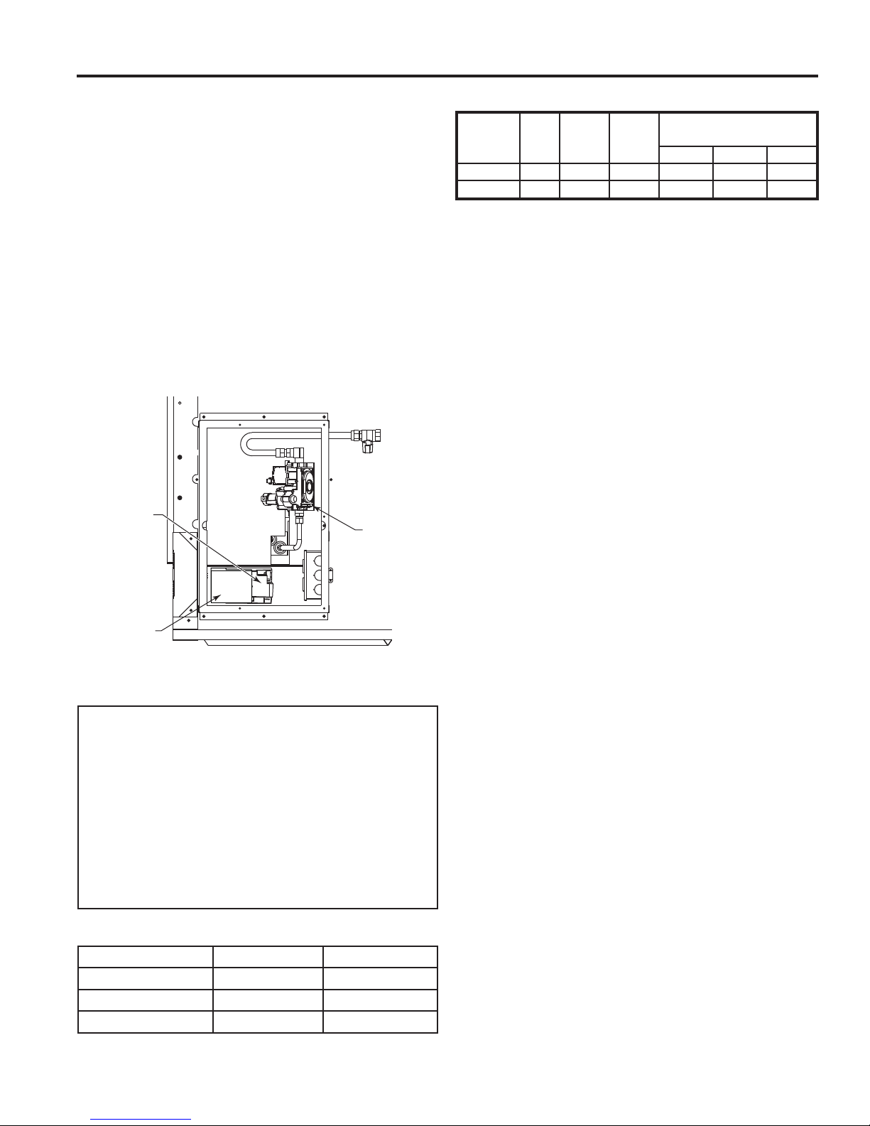
Control Board
Gas Control
Valve
A/C Module
Figure 1 VWDV70 Fireplace Features
FP2938
Side View
HIGH ELEVATIONS
Input ratings are shown in BTU per hour and are certifi ed
without derating for elevations up to 4,500 feet (1,370
m) above sea level.
For elevations above 4,500 feet (1,370 m) in USA,
installation must be in accordance with the current ANSI
Z223.1/NFPA 54 and/or local codes having jurisdiction.
In Canada, please consult provincial and/or local authorities having jurisdiction for installation at elevations above
4,500 feet (1,370 m).
GAS PRESSURES
Natural Propane (LP)
Inlet Minimum 4.5" w.c. 11.0" w.c.
Inlet Maximum 10.5" w.c. 13.0" w.c.
Manifold Pressure 3.5" w.c. 10.0" w.c.
GAS SPECIFICATIONS & ORIFICE SIZE
Max. Min.
Input Input Orifi ce Sizes
Model Fuel Btu/hr Btu/hr Left Middle Right
VWDV70 Nat. 51,000 32,500 #44 #43 #45
VWDV70 LP 43,000 32,000 1.25 mm 1.20 mm #56
BEFORE YOU ST ART
Read this homeowner manual thoroughly and follow all
instructions carefully. Inspect all contents for shipping
damage and immediately inform your dealer if any damage
is found. Do not install any unit with damaged, incomplete,
or substitute parts. Check your packing list to verify that
all listed parts have been received. You should have the
following:
• Fireplace (Firebox and Burner System)
• Refl ective Decorative Glass • Conversion Kit
• Stone Set • Wall Switch Kit
ITEMS REQUIRED FOR INSTALLATION
• Phillips Screwdriver • Framing Materials
• Hammer • Wall Finishing Materials
• Saw and/or saber saw • Level
• Measuring Tape • Pliers
• Electric Drill and Bits • Square
• Pipe Wrench • Tee Joint
• Caulking Material (noncombustible)
• Fireplace Surround Material (noncombustible)
• Piping Complying with Local Codes
• Pipe Sealant Approved for use with Propane/LPG
(Resistant to sulfur compounds)
• Noncombustible fi nishing material or dura-rock*
* Only used if desired to cover painted face other than using tiles or
marble. If tiles or marble are used around the face, the noncombustible
material is not needed.
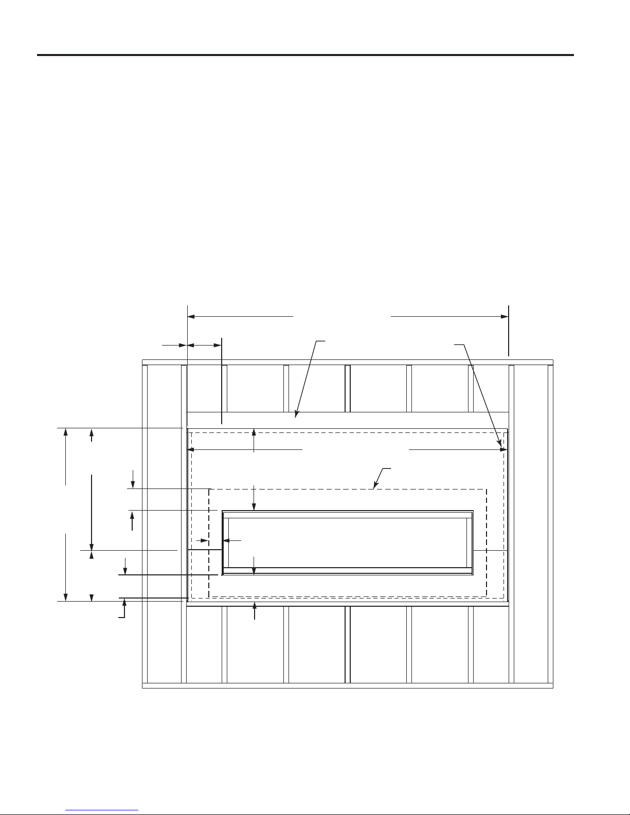
FIREBOX FRAMING
Firebox framing can be built before or after the appliance
is set in place. Refer to Figure 2 for fi replace and framing
dimensions. The framing headers may rest on the top of the
fi rebox standoffs. Do not bring headers below top of stand-
offs. NOTE: When planning your framing and installation,
keep in mind that both the gas line and electricity should
come in on the right side of the fi rebox (as you are facing
the front of the fi replace).
The fi rebox may be installed directly on a combustible fl oor
or raised on a platform of an appropriate height. When
the fi rebox is installed directly on carpeting, tile, or other
combustible material, other than wood fl ooring, the fi rebox
shall be installed on a metal or wood panel extending the
full width and depth of the enclosure.
20306745
5
VWDV70 Series Gas Fireplace
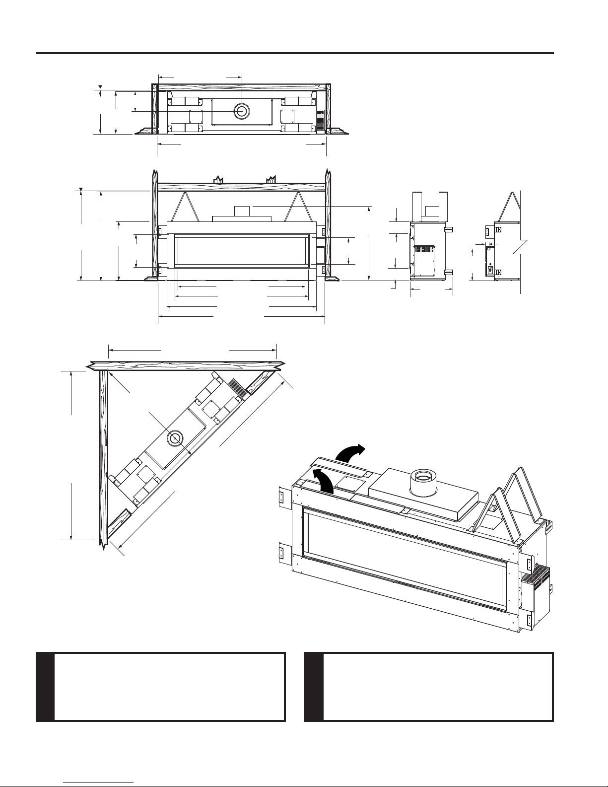
FIREPLACE AND FRAMING DIMENSIONS
Rough
Opening
Height
4856O”
(1232 mm)
Rough
Opening
Depth
236"
(594 mm)
4856M"
(1226 mm)
(276 mm)
2356”
(587 mm)
316”
(803 mm)
(451 mm)
10(6”
176M”
456QE” (1151 mm)
*9156” (2315 mm) Rough Opening Width
6956O" (1765 mm)
726M” (1848 mm)
816” (2067 mm)
906” (2302 mm)
906QE” (2294 mm)
(1029 mm)
1456O”
(368 mm)
*NOTE: Critical dimension. Do not exceed
this dimension for mounting noncombustible wall board. Refer to Page 10.
66QE”
(167 mm)
4056O”
16M”
(45 mm)
176"
(440 mm)
66QE”
(167 mm)
2356”
(587 mm)
63(6”
(1622 mm)
906QE” (2294 mm)
6M” (3245 mm)
127
Figure 2 Fireplace and Framing Dimensions
Do not fill spaces around firebox with
insulation or other materials. This could
cause a fi re.
WARNING
Unfold standoffs into upright position and fasten into place
using #8 screws provided, three (3) screws per standoff.
Figure 3
Figure 3
FP2931
Unit framing is to be rectangular front to
back. Failure to do so will cause fi re and
damage to property.
WARNING
6
20306745
PRE-INSTALLATION INFORMATION
VWDV70 Series Gas Fireplace
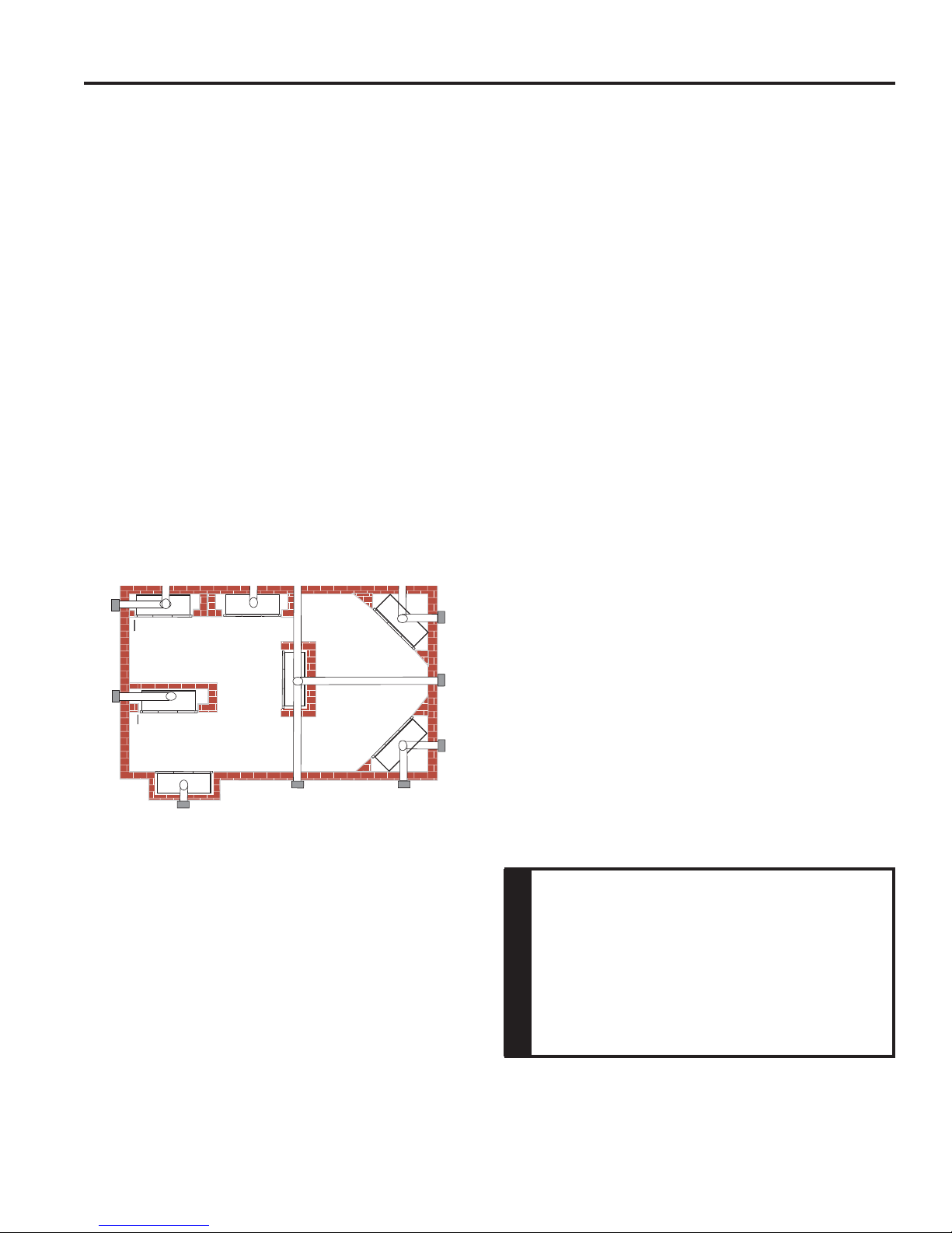
FIREPLACE LOCATION
Plan for the installation of your appliance. This includes
determining where the unit is to be installed, the vent
confi guration to be used, framing and fi nishing details,
and whether any optional accessories (i.e. blower, wall
switch, or remote control) are desired. Consult your local
building code agency to ensure compliance with local
codes, including permits and inspections.
The following factors should be taken into consideration:
• Clearance to side-wall, ceiling, woodwork, and windows.
Minimum clearances to combustibles must be main-
tained.
• This fi replace may be installed along a wall, across a
corner, or use an exterior chase. See Figure 4 for sug-
gested locations.
• Location should be out of high traffi c areas and away
from furniture and draperies due to heat from appliance.
• Never obstruct the front opening of the fi replace.
• Do not install in the vicinity where gasoline or other
fl ammable liquids may be stored.
• Vent pipe routing. See Venting section found in this
manual for allowable venting confi gurations.
E
Y
A
C
B
X
• These units can be installed in a bedroom. Refer to
the National Fuel Gas Code ANSI Z233.1/NFPA 54
— (current edition), the Uniform Mechanical Code —
(current edition), and Local Building Codes for specifi c
installation requirements.
• These units can be installed in a bathroom.
COLD CLIMATE OPTION
Your fi replace is equipped with an intermittent pilot ignition
(IPI) control. An IPI control with a standing pilot option
provides the dual benefi t of an economical and environ-
mentally responsible product and one which lights easily
even in the coldest climates. When in intermittent pilot
mode (as it comes from the factory), your pilot remains
unlit until needed, saving you fuel. Standing pilot mode,
by comparison, is characterized by a continuously burning
pilot. The benefi t of a pilot which lights only when needed
is fuel savings. However, with no pilot burning in your fi
replace, units operating in colder climates may experience
delayed start up or lock out. Because colder air is heavier
than milder air and there is no pilot burning to maintain
a warm stable temperature in your fi rebox, establishing
a draft to aid ignition becomes diffi cult. This is perfectly
normal but can be somewhat frustrating. To remedy this
issue, your fi replace has been designed with a cold cli-
mate pilot option, which, when active, maintains a warmer
temperature inside your fi rebox to make ignition faster and
more effi cient. Operating your appliance in cold climate
(aka standing) pilot mode will prohibit the need for multiple
ignition attempts and will prevent the system from delaying
start up or locking out.
D
Y
F
B
A Flat on Wall
B Cross Corner
C Island**
D Room Divider*
E Flat on Wall Corner*
F Chase Installation
Y 4" Minimum
** Island (C) and room divider (D) installation is possible as long
as the horizontal portion of vent system (X) does not exceed
20'. Refer to Installing Horizontal Termination Confi guration
on Page 13.
* When you install your fi replace in (D) room divider or (E) fl at
on wall corner positions (Y), a minimum of 6" clearance must
be maintained from perpendicular wall and front of fi replace.
Figure 4 Possible Fireplace Locations
20306745
To activate cold climate mode:
1. Holding the ON button the Command Center while
turning on the master switch. This action will toggle
between the standing (cold climate) pilot and intermittent pilot.
2. After performing the above operation, a confi rmation
beep will sound (one beep for standing pilot) or two
beeps (for intermittent pilot).
COLD CLIMATE INSULATION
If you live in a cold climate, seal all cracks
around your appliance, and wherever cold air
could enter the room, with noncombustible
material. It is especially important to insulate
NOTE
the outside chase cavity between the studs
and under the fl oor on which the appliance
rests, if the fl oor is above ground level.
NOTE: Refer to cold climate pilot information on Page 38
for more information on standing pilot vs. intermittent pilot
options.
7
VWDV70 Series Gas Fireplace
CLEARANCES TO COMBUSTIBLES
Follow these instructions carefully to
ensure safe installation. Failure to follow
in struc tions exactly can create a fi re hazard.
The appliance cannot be installed on a carpet,
tile or other combustible material other than
wood fl ooring. If installed on carpet or vinyl
fl ooring, the appliance shall be installed on
WARNING
a metal, wood or noncombustible material
panel ex tend ing full width and depth of the
appliance.
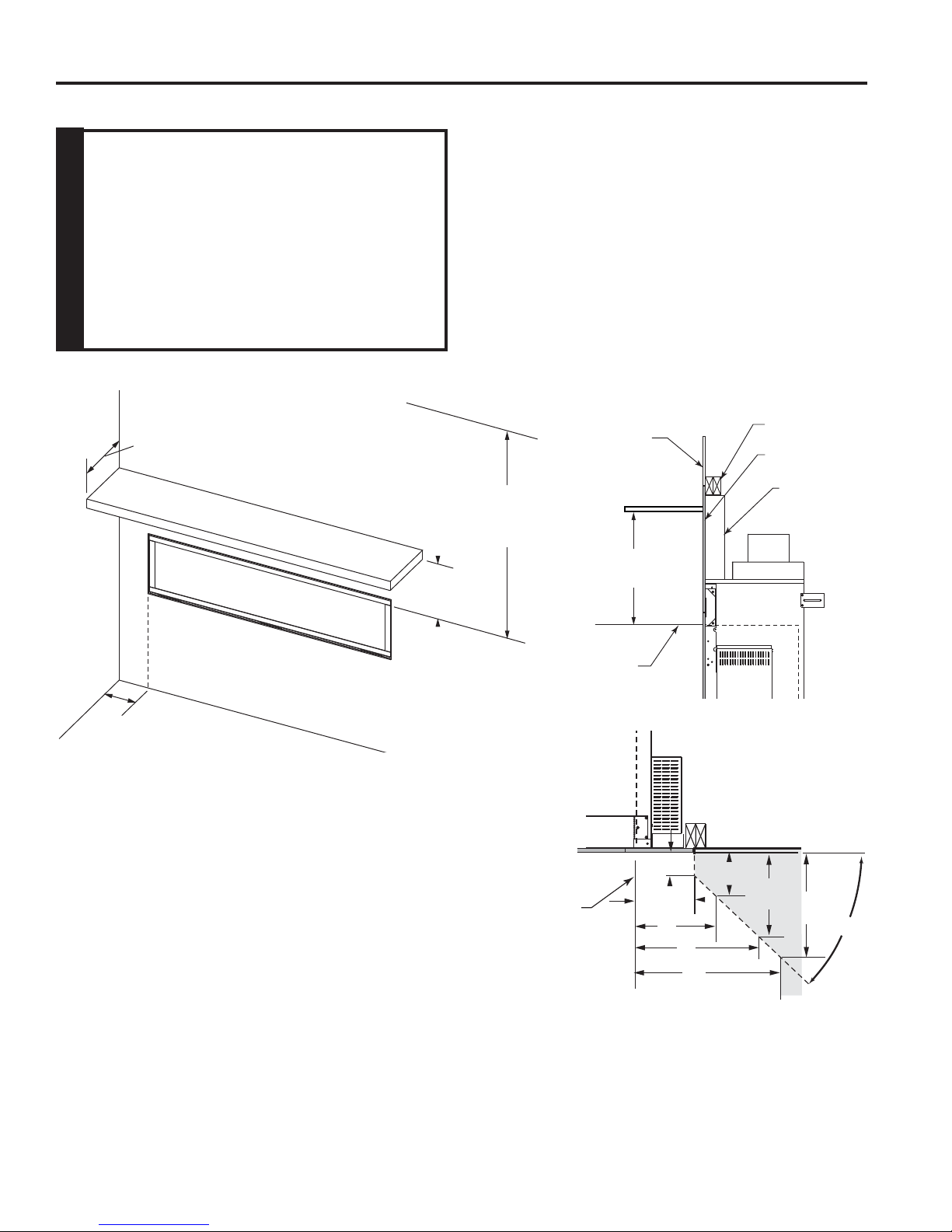
CLEARANCES
12“ (305 mm)
Max. Depth
956O”
(241 mm)
FP2928
Figure 5 Ceiling and Sidewall Clearances
NOTE: Refer to mantel installation instructions
on Page 11.
30” (762 mm)
Min. to Ceiling
12” Min.
From Opening
Side of
Fireplace Opening
(305 mm)
Top of Fireplace
Opening
FP2930
Top View
Wall
12” (305 mm)
12”
Side View
1”
256O”
3”
5”
6”
Stud
Noncombustible
Material (Supplied)
Standoff
FP2929
156O”
356O”
456O”
45°
8
Figure 6 Mantel clearances
20306745
SECURE FIREPLACE TO FLOOR OR FRAMING
The fi replace must be secured to the fl oor and/or to framing studs as shown in Figure 7. Use two (2) wood screws or
masonry/ concrete screws to secure fi replace to the fl oor. Use four (4) screws to attach fi replace to framing. The side
nailing fl anges are 1/2" or 5/8" to accommodate different wall thickness.
VWDV70 Series Gas Fireplace
Fireplace may be installed on top of framing or platform constructed of combustible
materials which do not protrude beyond
NOTE
the face.
Noncombustible
Material Supplied
Must be used to
create Four (4) Sides
Never install combustible materials over
front face of fi replace or in noncombustible
zone shown below.
NOTE
Noncombustible
Material (Supplied)
Framing Members
Nailing Flanges
Noncombustible
Material
Figure 7 Secure Fireplace to Framing Studs
FINISHING MATERIAL
NOTE: Any wiring must be done prior to fi nal fi nishing to
avoid costly reconstruction.
Only noncombustible materials (i.e. brick, tile, slate, steel,
or other materials with a UL fi re rating of Zero) may be used
to cover up the black face up to the fi replace glass door
opening. It is permissible to bring combustible wall board
to the top of the standoffs on the top and the sides of the
unit. A 300°F minimum adhesive may be used to attach
facing materials to noncombustible surface.
20306745
FP2932
IMPORTANT
If the unit is being installed in a bare painted
wall without finishing materials (i.e. brick,
tile, slate, marble, etc.), a Vermont Casting accessory face MUST be used (VWDV70CSS, VWDV70BT, VWDV70IA, etc.).
The supplied noncombustible board shown in
Figure 6 MUST be used for ALL installations.
9
VWDV70 Series Gas Fireplace
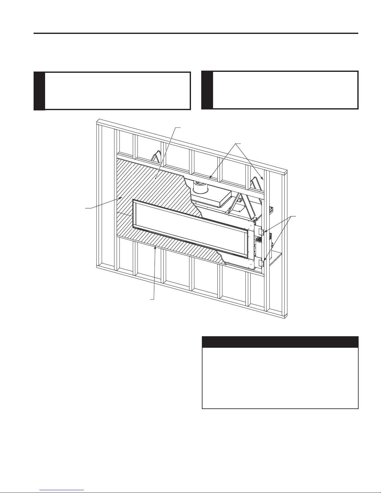
NONCOMBUSTIBLE REQUIREMENTS
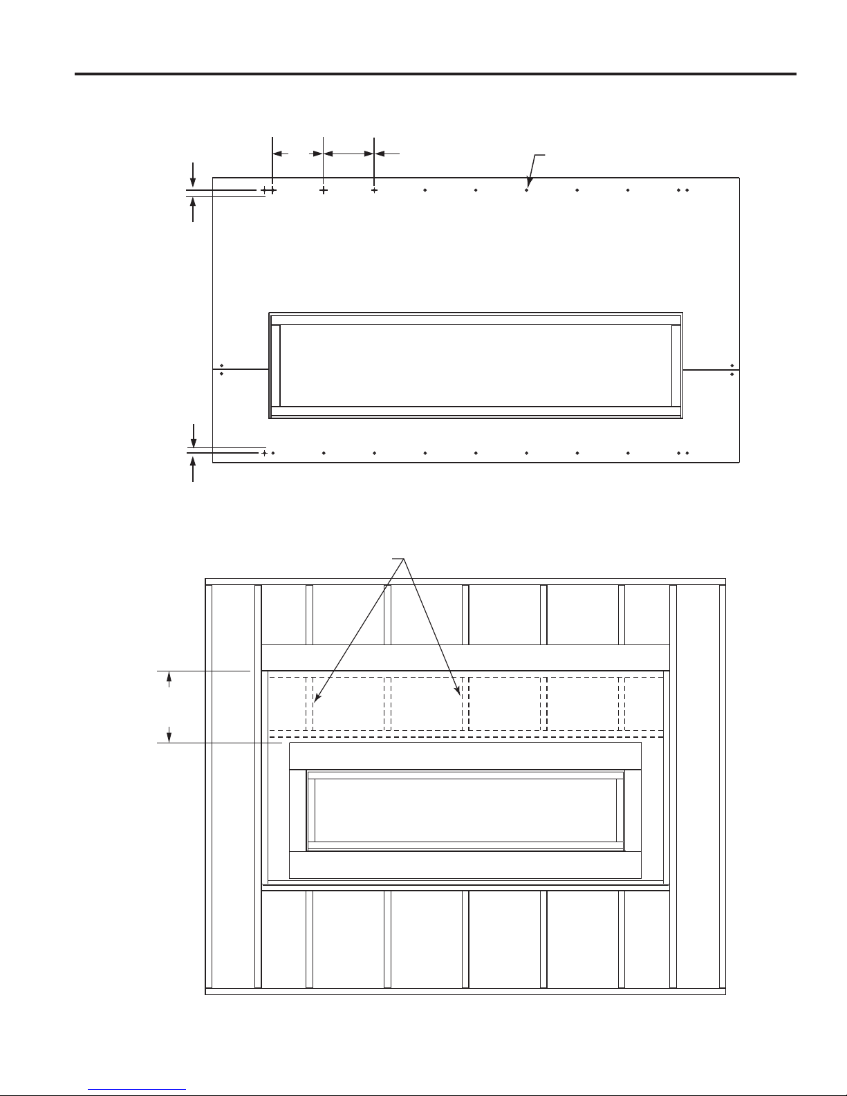
NONCOMBUSTIBLE FACING INSTALLATION
CAUTION: The noncombustible wall board supplied with
this unit can be damaged if dropped or struck. Handle
with care.
1. Using drywall screws secure noncombustible board to
framing and top nailing strip. Attach every 6" (152 mm).
Figures 8 & 9
IMPORTANT: To avoid cracking the board, pre-drill
holes prior to securing to unit/framing.
2. Wipe any debris or dust from the noncombustible board
and drywall.
3. It is highly recommended to prime the facing using a
quality primer prior to taping and mudding. This will
ensure proper adhesion of both the tape and mud. The
supplied board is very porous.
10”
(254 mm)
4. Tape the seams using a mesh type tape.
5. Mud seams as normal. We recommend using a product
called Durabond high strength compound for the fi rst
coat. This product can be purchased at any hardware
store. Follow manufacturer's recommendations for
curing the mud.
NOTE: Depending upon the fi nal fi nishing method, use a
minimum rated 300 degree sealant, drywall compound
or thin set to seal the side and top joints.
6. Prime wall for a second time for proper adhesion of
paint.
*Do Not Exceed This Dimension
*9156” (2315 mm)
Header
Framing
(838 mm)
506QE”
(1284 mm)
176QE”
(446 mm)
Figure 8
33”
656M”
(159 mm)
656M”
(159 mm)
2356QE”
(608 mm)
3(6” (98 mm)
76M” (197 mm)
92” (2337 mm)
Wall Board
Outline of
Face
FP2939
10
20306745
NONCOMBUSTIBLE REQUIREMENTS
VWDV70 Series Gas Fireplace
NOTE: Use this illustration as a guide when attaching the noncombustible boards to the structural framing. Use the #8
x 3/4" self-tapping screws provided.
#8 x 3/4" Self-tapping
Screws (supplied)
Figure 9
2" (51 mm)
from edge
1 1/2" (38 mm)
from edge
9"
9" (229 mm)
Spacing
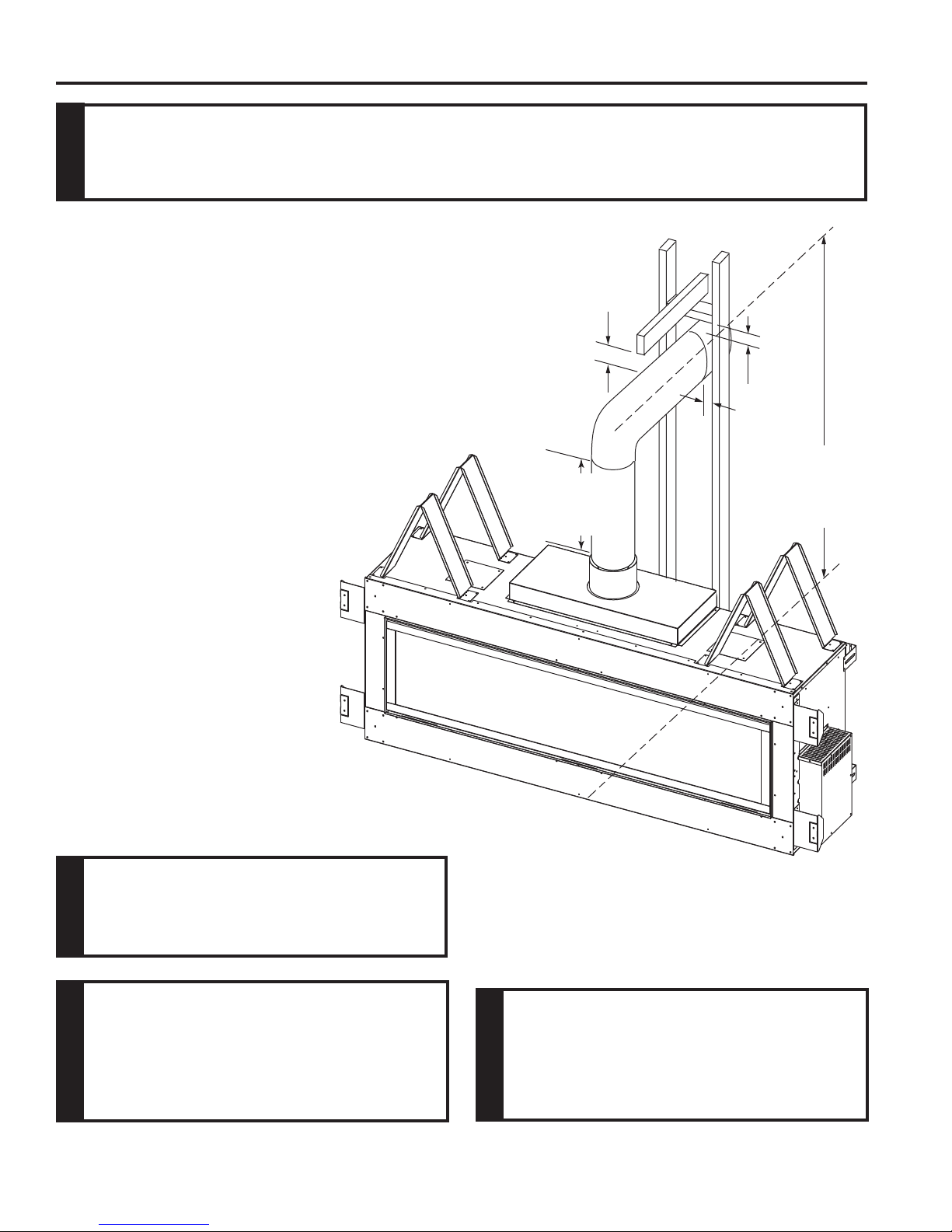
If a mantel will be installed and the attachment points fall upon the noncombustible surface above the glass frame opening,
a suitable structure must be added in order to support the weight of the mantel. A framework of metal studs as shown in
Figure 10 is suggested. The two (2) front stand-offs on top of the unit will need to be removed.
Metal Framing
Maintain 161⁄2"
(419 mm) to
Combustible Framing
Figure 10
20306745
FP2941
11
VWDV70 Series Gas Fireplace
VENTING INSTALLATION
Read all instructions completely and thoroughly before attempting installation. Failure to do so
could result in serious injury , property damage or loss of life. Operation of improperly installed
and maintained venting system could result in serious injury, property damage or loss of life.
WARNING
INSTALLATION PRECAUTIONS
Consult local building codes before beginning the
installation. The installer must make sure to select the
proper vent system for installation. The approved 5 x 8
venting components are Duravent and Selkirk products
listed on Page 49. UL1777 flexible venting is also
approved for use on these models. Before installing vent
kit, the installer must read this fi replace manual and vent
kit instructions.
Only a qualifi ed installer/service person should install vent-
ing system. The installer must follow these safety rules:
• Wear gloves and safety glasses for protection.
• Use extreme caution when using ladders or when
on rooftops.
• Be aware of electrical wiring locations in
walls and ceilings.
The following actions will void the warranty on your venting system:
**3”
(76 mm)
36" (914 mm)
Vertical Rise
Required Before
Horizontal Run
*1”
(25 mm)
84" (2134 mm)
Minimum, Base
of Fireplace to
Centerline of Vent
Pipe
• Installation of any damaged venting
component.
• Unauthorized modification of the
venting system.
• Installation of any component part
not manufactured or approved by
Vermont Castings Group.
• Installation other than permitted by
these instructions.
Failure to follow these instructions will
void the warranty.
NOTICE
This fireplace must be vented to the
outside. The venting system must NEVER
be attached to a chimney serving a separate
solid fuel burning appliance. Each gas
appliance must use a separate vent system.
WARNING
Do not use common vent systems.
12
Figure 11 Combustible Clearances for Vent Pipe
* A minimum 3" clearance to combustibles permitted all around fl ue at
outside wall.
** A minimum of 3" clearance is required above the pipe along
horizontal run until terminated through the wall.
FP2933
Horizontal sections of this vent system
require a minimum of 3" clearance to
combustibles on top of horizontal run until
terminated through the wall and 1" on all
sides. Vertical sections of this vent system
WARNING
require 1" clearance around all sides.
20306745
VENTING INSTALLATION
VWDV70 Series Gas Fireplace
INSTALLATION PLANNING
There are two basic types of direct-vent installation:
• Horizontal Termination
• Vertical Termination
It is important to select the proper length of vent pipe for
the type of termination you choose. It is also important to
note the wall thickness.
FOR HORIZONTAL TERMINATION
Select the amount of vertical rise desired. All horizontal run
of venting must have 1/4" rise for every 12" of run towards
the termination below 71⁄2" feet of vertical rise from the fl oor
of the fi replace. With 71⁄2" feet or more vertical rise from
the fl oor of the fi replace, the horizontal run may run level.
NEVER run vent piping down.
You may use up to three 90° elbows in this vent confi gura-
tion. Refer to Vertical/Horizontal Termination Confi gurations
on Page 15.
FOR VERTICAL TERMINATION
Measure the distance from the fi replace fl oor to the ceil-
ing. Add the ceiling thickness, the vertical rise in an attic
or second story, and allow for suffi cient vent height above
the roof line.
NOTE: You may use two 45° elbows in place of a 90° elbow.
You must follow rise to run ratios when using 45° elbows.
The appliance is approved for use with three 90° elbows
maximum or a combination of 90° and 45° elbows up to
a maximum of 270°.
Never run the vent pipe level down. This
may cause excessive temperatures which
could cause a fi re.
WARNING
For two-story applications, fi restops are required at each
fl oor level. If an offset is needed in the attic, additional pipe
and elbows will be required.
You may use a chase with a vent termination with exposed
pipe on the exterior of the house.
Refer to Installing A Vent System in an Outside Chase
below. If pipe is enclosed in chase, it is not exposed.
It is very important that the venting system maintain its
balance between the combustion air intake and the fl ue
gas exhaust. Certain limitations apply to vent confi gurations
and must be strictly followed.
INSTALLING A VENT SYSTEM IN AN
OUTSIDE CHASE
A chase is a vertical boxlike structure built to enclose
venting that runs along the outside of a building. A chase
is required for such venting.
When installing in a chase, you should
insulate the chase as you would the outside
walls of your home. This is especially
important in cold climates. Insulation
should be considered a combustible
NOTICE
material. Maintain proper clearances to all
combustible materials.
Treatment of fi restops and construction of
the chase may vary from building type to
building type. These instructions are not
substitutes for the requirements of local
NOTICE
building codes. You must follow all local
building codes.
20306745
Top Vent Vertical Side wall: Horizontal
sections of this vent system require a
minimum of 3" (76 mm) clearances to
combustibles at the top of the fl ue and 1"
(25 mm) clearance at the sides and bottom
until the fl ue penetrates the outside wall. A
minimum 1" clearance all around the fl ue
WARNING
is acceptable at this point of penetration. If
vertical rise is 71/2 feet (2.3 m) or higher when
top venting, the clearance to combustibles
is 1" on all sides of the horizontal run.
13
VWDV70 Series Gas Fireplace
V
X
X
X
D
E
B
B
B
C
B
M
B
A
J
K
F
L
VENT TERMINATION AIR SUPPLY INLET
AREA WHERE TERMINAL IS NOT PERMITTED
H
I
Fixed
Closed
Operable
Operable
Fixed
Closed
B
INSIDE
CORNER DETAIL
A
G
CFM145a
V
V
V
V
V
V
V
V
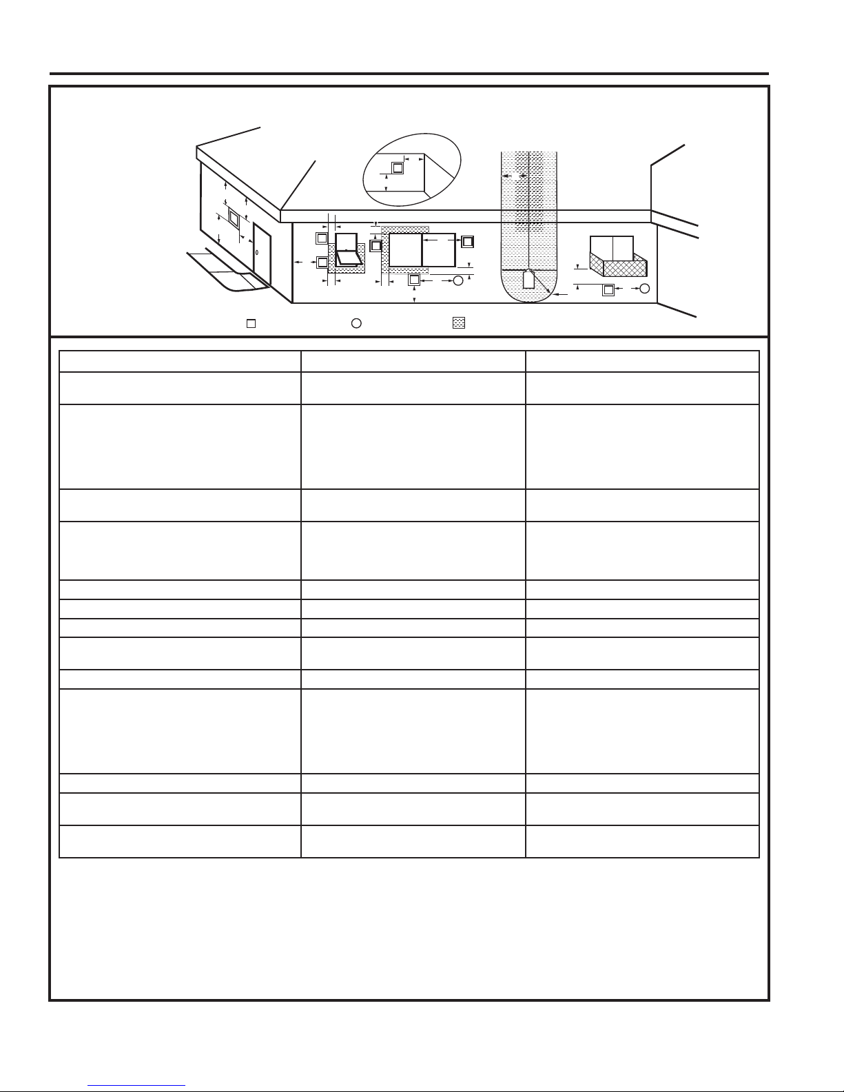
GENERAL VENTING INFORMATION - TERMINATION LOCATION
Figure 12 –
Termination Locations
VENTING INSTALLATION
A = Clearance above grade, veranda, porch,
CANADIAN INSTALLATIONS
1
12" (30cm) 12" (30cm)
US INSTALLATIONS
2
deck or balcony
B = Clearance to window or door that may be
opened
C = Clearance to permanently closed window 12" (305mm) recommended to prevent
D = Vertical clearance to ventilated soffi t
6" (15cm) for appliances <10,000 BTU/h
(3kW)
12" (30cm) for appliances >10,000 BTU/h
(3kW) and <100,000 BTU/h (30kW)
36" (91cm) for appliances >100,000 BTU/h
(30kW)
6" (15cm) for appliances <10,000 BTU/h
(3kW)
9" (23cm) for appliances >10,000 BTU/h
(3kW) and <50,000 BTU/h (15kW)
12" (30cm) for appliances >50,000 BTU/h
(15kW)
12" (305mm) recommended to prevent
window condensation
window condensation
18" (458mm) 18" (458mm)
located above the terminal within a horizontal distance of 2' (610 mm) from the
center line of the terminal
E = Clearance to unventilated soffi t 12" (305mm) 12" (305mm)
F = Clearance to outside corner see next page see next page
G = Clearance to inside corner see next page see next page
H = Clearance to each inside of center line
extended above meter/regulator assembly
3' (91cm) within a height of 15' (5m) above
the meter/regulator assembly
3' (91cm) within a height of 15' (5m) above
the meter/regulator assembly
I = Clearance to service regulator vent outlet 3' (91cm) 3' (91cm)
J = Clearance to non-mechanical air supply
inlet to building or the combustion air inlet
to any other appliance
6" (15cm) for appliances <10,000 BTU/h
(3kW)
12" (30cm) for appliances >10,000 BTU/h
(3kW) and <100,000 BTU/h (30kW)
36" (91cm) for appliances >100,000 BTU/h
(30kW)
6" (15cm) for appliances <10,000 BTU/h
(3kW)
9" (23cm) for appliances >10,000 BTU/h
(3kW) and <50,000 BTU/h (15kW)
12" (30cm) for appliances >50,000 BTU/h
(15kW)
K = Clearance to mechanical air supply inlet 6' (1.83m) 3' (91cm) above if within 10' (3m) horizontally
L = Clearance above paved sidewalk or
7' (2.13m)
†
7' (2.13m)
†
paved driveway located on public property
M = Clearance under veranda, porch, deck or
12" (30cm)
‡
12" (30cm)
‡
balcony
1 In accordance with the current CSA-B149 Installation Codes
2 In accordance with the current ANSI Z223.1/NFPA 54 National Fuel
Gas Codes
† A vent shall not terminate directly above a sidewalk or paved
driveway which is located between two single family dwellings and
serves both dwellings
‡ Only permitted if veranda, porch, deck or balcony is fully open on a
minimum 2 sides beneath the fl oor.
14
NOTE: 1. Local codes or regulations may require different
2. The special venting system used on Direct Vent
3. Vermont Castings Group assumes no responsibility for
clearances.
Fireplaces are certifi ed as part of the appliance, with
clearances tested and approved by the listing agency.
the improper performance of the appliance when the venting
system does not meet these requirements.
20306745
VENTING INSTALLATION
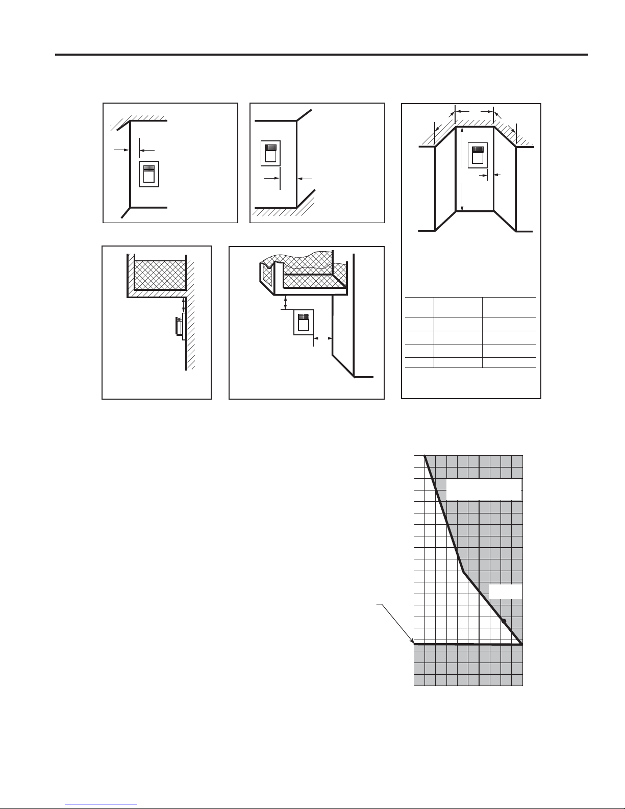
TERMINATION CLEARANCES
Termination clearances for buildings with combustible and non-combustible exteriors.
Inside Corner
G
V
G =
Combustible
6" (152 mm)
Noncombustible
2" (51 mm)
Outside Corner
V
F
F =
Combustible
6" (152 mm)
Noncombustible
2" (51 mm)
Alcove Applications*
VWDV70 Series Gas Fireplace
D
C
O
C
V
E
Balcony -
with no side wall
Balcony -
with perpendicular side wall
E = Min. 2” (51 mm) for
non-vinyl sidewalls
Min. 12” (305 mm) for
vinyl sidewalls
O = 8’ (2.4 m) Min.
M
V
M
V
P
M =
Combustible &
Noncombustible
12" (305 mm)
*NOTE: Termination in an alcove space (spaces open only on one side and with an overhang) is permitted with the dimensions specifi ed for vinyl or non-vinyl siding and soffi ts. 1. There must be a 3’
(914 mm) minimum between termination caps. 2. All mechanical air intakes within 10’ (1 m) of a termination cap must be a minimum of 3’ (914 mm) below the termination cap. 3. All gravity air intakes
within 3’ (914 mm) of a termination cap must be a minimum of 1’ (305 mm) below the termination cap.
Combustible &
Noncombustible
M = 12" (305 mm)
P = 6” (152 mm)
No. of
Caps DMIN.CMAX.
1 3' (914 mm) 2 x D
2 6' (1.8 m) 1 x DACTUAL
3 9' (2.7 m) 2/3 x DACTUAL
4 12' (3.7 m) 1/2 x DACTUAL
DMin. = Number of Termination caps x 3
CMax. = (2 / Number termination caps) x DActual
ACTUAL
Figure 13 Termination Clearances
40
38
HOW TO USE THE VENT GRAPH
The Vent Graph should be read in conjunction with the
following vent installation instructions to determine the
relationship between the vertical and horizontal dimensions
of the vent system.
1. Determine the height of the center of the horizontal vent
pipe exiting through the outer wall. Using this dimension
on the Sidewall Vent Graph below, locate the point
intersecting with the slanted graph line.
2. From the point of this intersection, draw a vertical line
to the bottom of the graph.
3. Select the indicated dimension, and position the fi re-
place in accordance with same.
Example: If the vertical dimension from the base of the
fi replace is 11' (3.4 m) the horizontal run to the face of
the outer wall must not exceed 16' (4.9 m).
Sidewall Vent Graph showing the relationship between
vertical and horizontal dimensions for a Direct Vent fl ue
system.
36
34
32
30
28
26
24
Dimensions in Feet
22
20
84" (2134 mm)
From Floor to
Center
18
16
14
12
10
8
6
4
2
Horizontal dimension from the fi nished outside wall
to the center of the pipe on the fi replace
Figure 14 Rear Wall Venting Graph
Vent run must not
be in shaded area
eg: A
2 4 6 8 10 12 14 16 18 20
Vertical Dimension from the Base of Unit
to the Center of the Horizontal Vent Pipe
20306745
15
VWDV70 Series Gas Fireplace
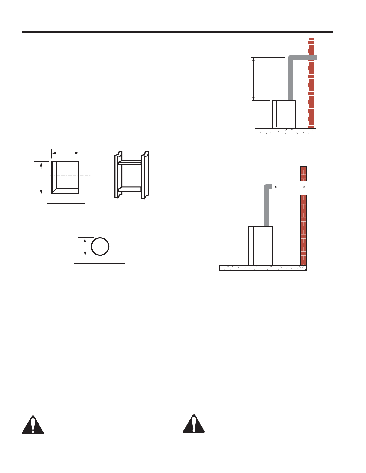
VERTICAL SIDEWALL INSTALLATION
Step 1
Locate vent opening on the wall. It may be necessary to
fi rst position the fi replace and measure to obtain hole lo-
cation. Depending on whether the wall is combustible or
noncombustible, cut opening to size. Figure 15 (For com-
bustible walls fi rst frame in opening.)
1
Combustible Walls: Cut a 10
mm) hole through the exterior wall and frame as shown.
Figure 15
Noncombustible Walls: Hole opening must be 8
mm) in diameter.
Vent Opening for Combustible Walls
101⁄2"
(267 mm) Min.
101⁄2"
(267 mm)
Min.
⁄2"H x 101⁄2"W (267 x 267
1
⁄2" (216
VENTING INSTALLATION
X
FP1181
Figure 16 Vertical Height Requirement
X
Fireplace Hearth Framing Detail
Opening for Noncombustible Wall
81⁄2"
(216 mm)
FP2293
Figure 15 -
Locate vent opening on wall
Fireplace Hearth
Step 2
Secure fi restop to the inside frame, center in the 101⁄2" x
1
⁄2" vent opening.
10
Step 3
Place fi replace into position. Measure the vertical height
(X) required from the base of the fl ue collars to the center
of the wall opening. Figure 16
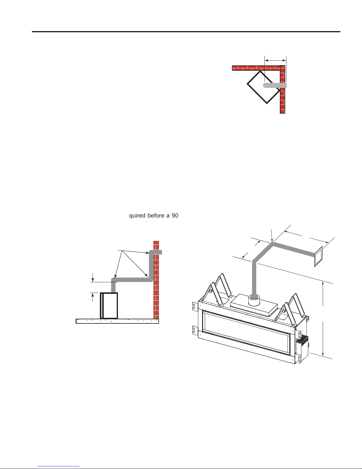
Step 4
Using appropriate length of pipe section(s) attach to fi re-
place with three (3) screws. Follow with the installation of
the elbow.
Step 5
Measure the horizontal length requirement fi guring a 11⁄4"
(32 mm) overlap, i.e. from the elbow to the outside wall
cap. Figure 17
FP1182
Figure 17 Horizontal Length Requirement
Step 6
Use appropriate length of pipe sections — telescopic or
fi xed — and install.
Sealing vent pipe and fi restop gaps with high tem-
perature sealant will restrict cold air being drawn in
around fi replace.
Step 7
Guide the vent terminations 5" and 8" collard into their
respective vent pipes. Double check that the vent pipes
overlap the collars by a minimum 11⁄4" (32 mm). Secure
the termination to the wall with screws provided and caulk
around the wall plate to weatherproof. As an alternative to
screwing the termination directly to the wall, you may also
use expanding plugs or an approved exterior construction
adhesive.
Always install horizontal venting on a level
plane.
16
Support horizontal pipes every 36" (914 mm)
with metal pipe straps.
20306745
VENTING INSTALLATION
VWDV70 Series Gas Fireplace
VERTICAL/HORIZONTAL TERMINATION
CONFIGURATIONS
Since it is very important that the venting system
maintain its balance between the combustion air intake
and the fl ue gas exhaust, certain limitations as to vent
confi gurations apply and must be strictly adhered to.
The Vent Graph, showing the relationship between vertical
and horizontal side wall venting, will help to determine the
various dimensions allowable. Figure 14
NOTE: Horizontal and vertical sections of this vent system
require a minimum of 3" (76 mm) clearance to combustibles
on all sides.
When vent exits through foundations less than 20" below
outcrop, the termination must be fl ush up with outcropped
wall above.
It is best to locate the fi replace in such a way that minimizes
the number of offsets and horizontal vent length.
The horizontal vent run refers to the total length of vent
pipe from the fl ue collar of the fi replace (or the top of the
Transition Elbow) to the face of the fi nished outside wall.
• The maximum number of 90° elbows per side wall
installation is three (3). Figure 18
• A minimum of 36" (914 mm) is required before a 90°
elbow. Figure 19
36"
(914 mm)
Max.
FP1177
Figure 19 Maximum Horizontal Run with No Rise
In Figures 20 and 21 dimension A plus B must not be
greater than 17' (5.2 m).
• For each 45° elbow installed in the horizontal run, the
length of the horizontal run MUST be reduced by 18"
(457 mm). This does not apply if the 45° elbows are
installed on the vertical part of the vent system.
• The maximum number of elbow degrees in a system is
270°. Figure 21
90° Elbow = 3' Reduction
3 x 90°
Elbows
36" (914 mm)
Min.
FP1176
Figure 18 Maximum Three (3) 90° Elbows Per Installation
• If a 90° elbow is used in the horizontal vent run (level
height maintained) the horizontal vent length is reduced
by 36". Refer to Figures 20 and 21. This does not apply if
the 90° elbows are used to increase or redirect a vertical
rise. Figure 20
Example: According to the vent graph (Page 15) the maximum horizontal vent length in a system with a 10' vertical
rise is 171⁄2' (5.3 m) and if a 90° elbow is required in the
horizontal vent it must be reduced to 141⁄2' (4.4 m).
A
Figure 20 Horizontal Run Reduction
10’
B
10'
(3 m)
FP2934
20306745
17
VWDV70 Series Gas Fireplace
VENTING INSTALLATION
Example: Elbow 1 = 90°
Elbow 2 = 45°
Elbow 3 = 45°
Elbow 4 = 90°
Total Angular Variation = 270°
1
2
3
4
36" (914 mm)
Minimum
Figure 21 Maximum Elbow Usage
FP1180
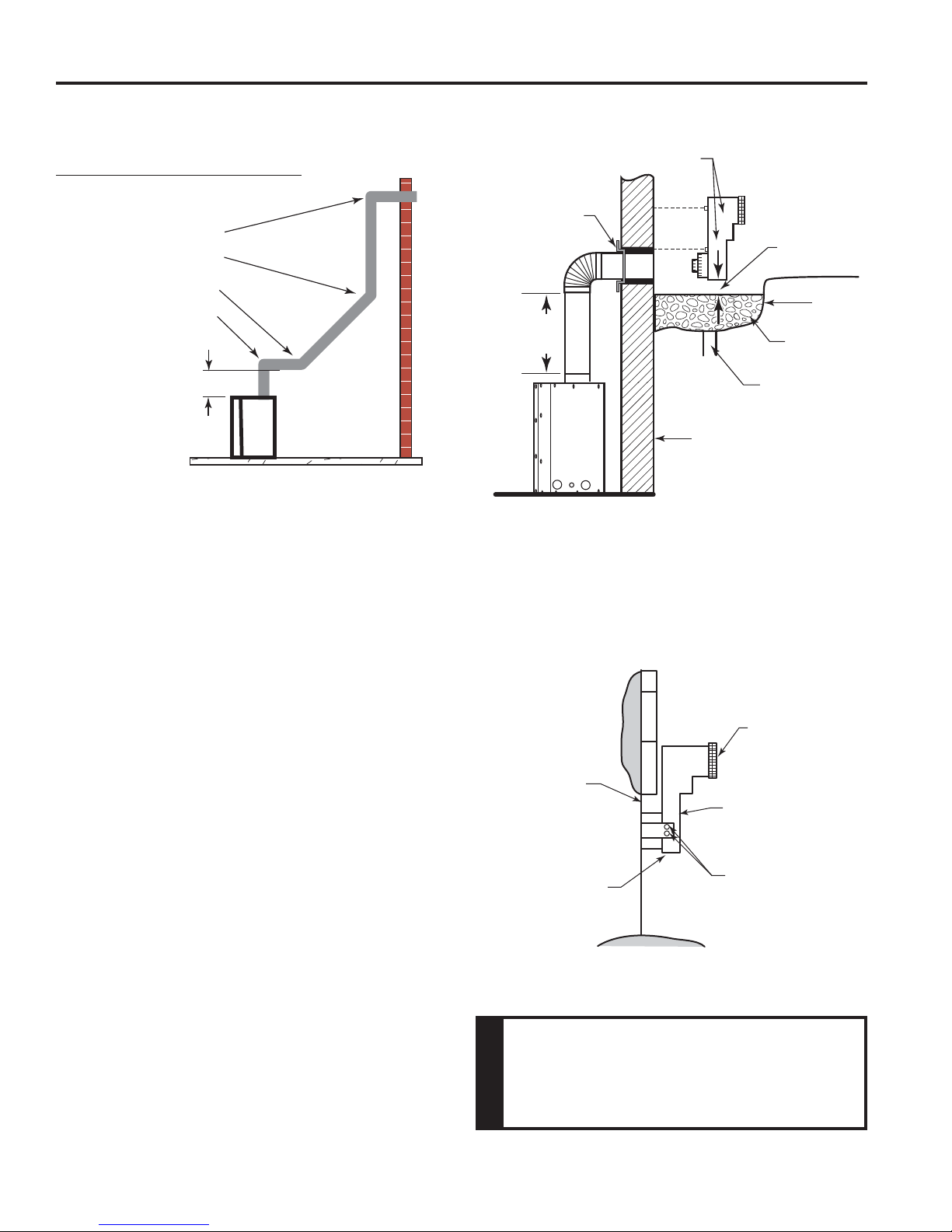
BELOW GRADE INSTALLATIONS
When it is not possible to meet the required vent terminal
clearances of 12" above grade level, a snorkel kit is recommended. It allows installation depth down to 7" (178
mm) below grade level. The 7" (178 mm) is measured
from the center of the horizontal vent pipe as it penetrates
through the wall.
Ensure that sidewall venting clearances are observed.
If venting system is installed below ground, we recommend a window well with adequate and proper drainage
to be installed around the termination area.
If installing a snorkel, a minimum 36" (914 mm) vertical
rise is necessary. The maximum horizontal run with the 36”
(914 mm) vertical pipe is 36". This measurement is taken
from the collar of the fi replace (or transition elbow) to the
face of the exterior wall. See the Sidewall Venting Graph
for extended horizontal run if the vertical exceeds 12".
1. Establish vent hole through the wall.
2. Remove soil to a depth of approximately 16" (406 mm)
below base of snorkel. Install drain pipe. Install window
well (not supplied). Refi ll hole with 12" (305 mm) of
coarse gravel leaving a clearance of approximately 4"
(102 mm) below snorkel. Figure 22
3. Install vent system.
4. Ensure a watertight seal is made around the vent pipe
coming through the wall.
5. Apply high temperature sealant caulking (supplied)
around the 5" and 8" snorkel collars.
6. Slide the snorkel into the vent pipes and secure to the
wall.
7. Level the soil so as to maintain a 4" clearance below
snorkel. Figure 19
Screws
Firestop
Minimum
4" Clearance
Ground
Window
36" (914 mm)
Minimum
Drain
Foundation Wall
FP2134
Figure 22 -
Below Grade Installation
Well
Gravel
If the foundation is recessed, use recess brackets (not
supplied) for securing lower portion of the snorkel. Fasten
brackets to wall fi rst, then secure to snorkel with self drilling
#8 x 1⁄2" sheet metal screws. It will be necessary to extend
vent pipes out as far as the protruding wall face. Figure 23
Snorkel
Foundation
Recess
Wall Screws
Watertight Seal
Around Pipe
Figure 23 Snorkel Installation, Recessed Foundation
Sheet Metal
Screws
• Do not back fi ll around snorkel.
• A clearance of at least 4" must be
maintained between the snorkel and
the soil.
WARNING
18
20306745
 Loading...