

Page 1
VCS6006 ASSEMBLY PROCEDURES
Tools Required: knife or scissors, Phillips or Robertson screwdriver, 7/16” wrench.
For shelf light and console back lights refer to ELECTRONIC INSTRUCTIONS.
For rotisserie setup refer to ROTISSERIE SETUP.
Step 1: Unpack Carton and Verify Contents
Use a sharp cutting tool to cut the straps on the packaging and then open the carton top. The sleeve
surrounding the barbecue can be removed by lifting it straight up and over the top of the unit. Unpack all
parts and c Next,
protective plastic coverings from the metal parts
ompare all contents to the parts list that accompanies this assembly manual. remove the
. Be careful not to scratch or damage the finish of the metal
parts when removing the protective plastic. Refer to the parts list for fastener detail.
CAUTION:
Some parts may have sharp edges; to avoid injury, wearing gloves during assembly is strongly
recommended
Page 1
50003789 01/06 Rev.0 En
Page 2
VCS6006 Assembly
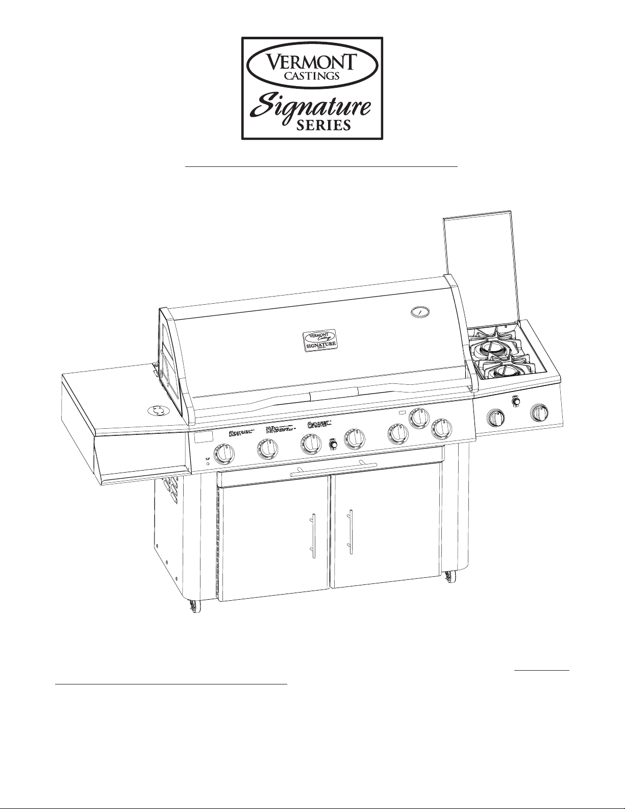
Step 2: Install Casters
Materials Required:
(4) casters.
Alternately prop up each end of the grill with a block of
wood or other solid item.
Position the caster pin to the proper opening at the
bottom of the grill.
Push the caster as far as possible.
Installation of the casters can be also done by rocking the
caster in a circular motion when starting the pin into the
opening.
NOTE:
Casters may not be exactly as shown depending
on your model.
Step 3: Install Internal Shelf
Materials Required:
Internal Shelf (1)
10-24 U-type Clip (1)
10-24 x 1/2” Long Black Bolt (1)
Plastic Push-in Fastener (2)
6” - 8”
(152 - 203mm)
Fig. 2
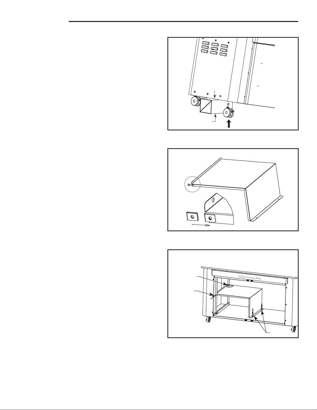
A.
Attach #10-24 U-type fastener to internal shelf as
shown (Fig. 3a)
NOTE:
The flat side of the U-type fastener must face
to the front of the grill and holes must be aligned.
B.
Attach internal shelf with the U-clip fastener inside
the cabinet. (Fig. 3b) Screw in 10-24 x 1/2” black bolt
through hole in the cabinet to previous installed Uclip.
Push in plastic push-in fasteners through holes in the
internal shelf to the holes in the bottom of the cabinet.
Fig. 3a
Fig. 3b
Slide onto bolt
holding back
panel on
Screw in
Push in
Page 2
Page 3
Step 4: Install Battery Shroud
VCS6006 Assembly
Materials Required:
Battery Shroud (1)
Plastic Push-In Fastener (1)
Slide the battery shroud onto the internal shelf and secure
with push-in fastener.
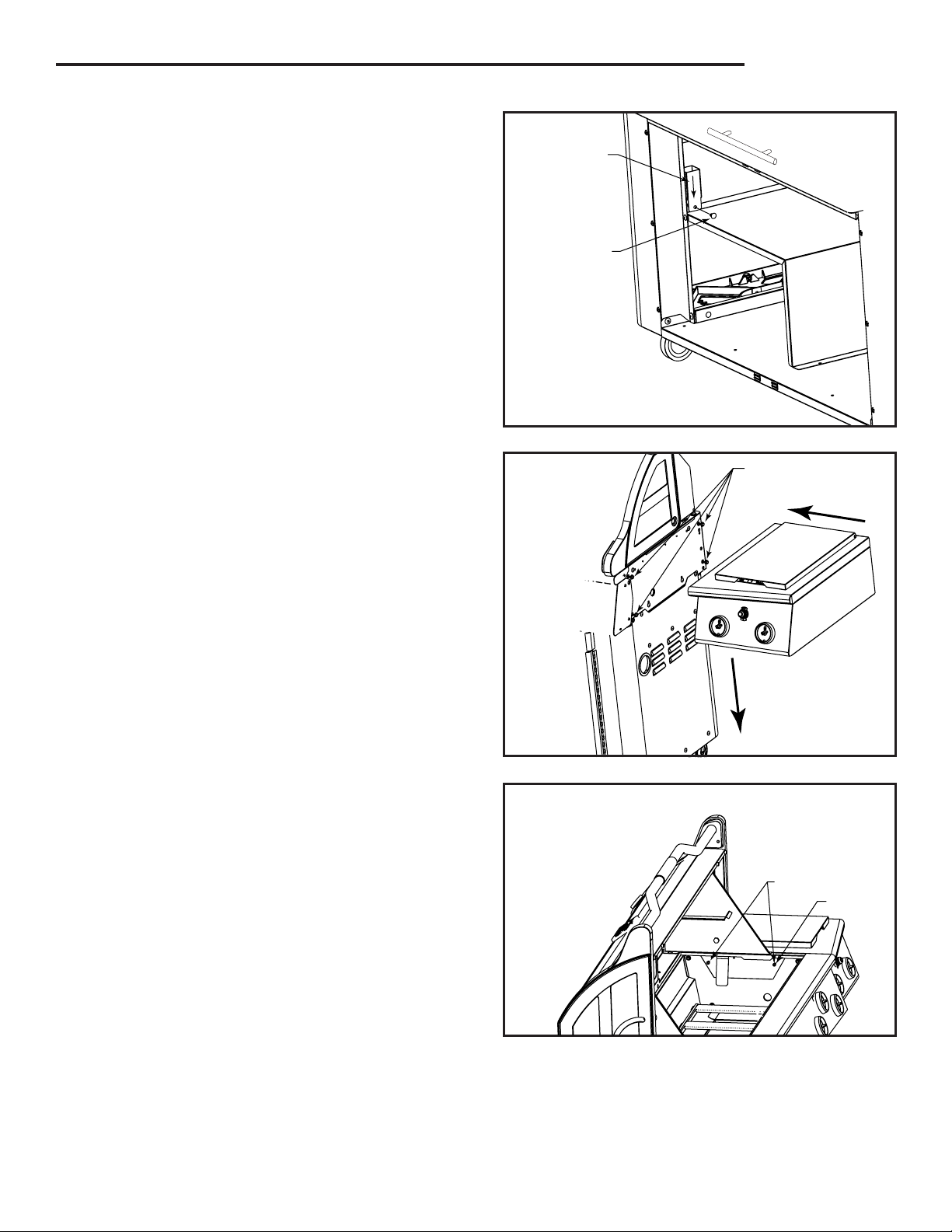
Step 5: Attach Side Shelves
(Left for Shelf Light, Right with Side Burner)
Materials Required:
Side Shelf Assembly Left (1)
Side Shelf Assembly Right (1) (shown)
1/4-20 x 1-1/2” Long Bolt (8)
#10-24 x 1/2” Long Black Bolt (3)
Battery Shroud
Push-in Fastener
Fig. 4
Bolts
Slide
A.
Loosely attach four (4) 1/4-20 x 1-1/2” long bolts to
pre-installed threaded inserts as shown in Figure 5a.
Attach side shelf assembly right over four (4) installed
bolts, then push it down to level with a combustion
box. Tighten the four (4) bolts fully.
Repeat on the other side for side shelf assembly left.
B.
Secure side shelf assembly right as shown in Figure
5b with two (2) #10-24 x 1/2” long black bolts.
Secure side shelf assembly left with one (1) #10-24 x
1/2” long black bolt at the front of the grill.
Push
Fig. 5a
Fig. 5b
Bolts
Front
Page 3
Page 4

VCS6006 Assembly
Step 6: Attach Condiment Tray to Console
(Part of Side Shelf Assembly Left)
Materials Required:
10-24 Nut Black (1)
10-24 x 1/2” Long s/s Bolt (1)
Secure Condiment Tray to console with stainless bolt and
nut. Ensure the surfaces of the condiment tray and
console are aligned.
Bolt
Tighten bolt and nut securely.
Step 7: Rotisserie Burner Electrode Wire, Side
Burner Hose
Attach rotisserie burner wire to the free port of
the electronic igniter as shown in Figure 7a.
Slide side burner hose through the bushing and
connect to the quick connector. (Fig. 7a)
Gas Supply Connection
TO CONNECT:
Push back the sleeve on the socket as shown.
1.
(Fig. 7b)
Nut
Fig. 6
Fig. 7a
Electronic Igniter
Rotisserie Burner Wire
Side Burner Hose
Bushing
Insert plug and release the sleeve (Fig. 7b)
2.
Push the plug until sleeve snaps forward to
3.
lock the plug in the socket.
WARNING:
Always conduct the following
safety tests before lighting the grill, to prevent
a possible fire or explosion. (Refer to leak test
below)
TO DISCONNECT:
Push sleeve back and pull the plug out.
1.
Page 4
Fig. 7b
Retract Sleeve
Release Sleeve
Page 5

VCS6006 Assembly
Step 8: Side Burner Grates, Side Burner Knobs
Materials Required:
Side Burner Grate (2)
Side Burner Knob (2)
Place side burner grates in proper position.
Attach knobs.
Step 9: Backlit Knobs
Materials Required:
Backlit Knob (7)
Attach to the console backlit knobs as shown.
Fig. 8
Side Burner Grates
Side Burner Knobs
Step 10: Attach Handle to Doors and Drawer
Materials Required:
Handle (3)
Secure the door handles (2) to the doors by inserting two
(2) screws (supplied with handles) through the circular
cutouts at the rear of the door panel and into the handle.
Attach third handle to the pull-out drawer above the
doors.
NOTE:
Handles may not be exactly as shown depending
on your model.
Note: If doors are not aligned or have shifted during
shipping, they can be adjusted by loosening the screws
which fasten the hinge of the door to the grill body and
shifting the doors until they are aligned. Once satisfied
with alignment, fully tighten the screws to secure the
doors into position.
Page 5
Fig. 9
Fig. 10
Page 6

VCS6006 Assembly
Step 11: Grease Tray and Grease Cups
Materials Required:
Grease Cups (2)
Grease Tray Assembly (1)
Place grease cups in position into openings in the
A.
upper base panel area. (Fig. 11a)
Place grease tray in position under the combustion
B.
area. (Fig. 11b)
Grease Cup Openings
Grease Cups
Fig. 11a
Fig. 11b
Detail A
Slide
See Detail A
Step 12: Install Internal Components
Materials Required:
Sear Plates (6) Cooking Grates (4)
Griddle Plate (1) Warming Rack (1)
Refer to Figure 12 for proper locations.
Place the sear plates into the base unit ensuring the
edges with the “finger holes” face the grill front.
Position the griddle plate and the cooking grates into
the base with the finger holes facing the front. Set
the warming rack into the two supports in the ends
of the rear lid.
Note:
One side of the Grate surface has a rounded
side suitable for meats and a flat side suitable for
delicate foods (i.e. fish). Grates can be turned over
according to your preference.
Caution:
Do not attempt to turn Cooking Grate over
while the Grill is in use and grates are hot. Doing so
could result in severe burns and other injuries.
Page 6
Sear plate
Warming
Rack
Cook Grate
Fig. 12
Griddle
Finger holes
at front
Page 7

VCS6006 Assembly
Step 13: Attach Stabilizer Bracket
Materials Required:
Stabilizer Bracket (2)
10-24 x 1/2” Long Black Bolt (4)
Attach the stabilizer brackets to the bottom panel.
Secure with four (4) bolts.
Step 14: Install the Tank Pull-Out and LP Cylinder
(LP models Only)
Materials Required:
Tank Pull-Out Kit
LP Gas Cylinder (Not included)
Fig. 13
Bolts
Stabilizers
Note:
Refer to the installation instructions included with
the tank pull-out kit for assembly procedures. Refer to
the User's Manual for the cylinder filling requirements,
regulator attachments and leak testing procedures, before
lighting the grill.
Insert the Propane(LP) Cylinder into the hole on Tank
Pull-Out.
Connect the regulator to the cylinder.
Fig. 14
Page 7
Page 8

VCS6006 Assembly
Step 15: Side Burner / Rotisserie Control Functions
Fig. 15
Rear Burner
Front Burner
Rotisserie
Burner and
Side Burner
Igniter
Control Knob for
Front Burner
Control Knob for
Rotisserie Burner
CFM Corporation
2695 Meadowvale Boulevard
Mississauga, Ontario L5N 8A3 Canada
(800) 668-5323
Page 8
www.cfmcorp.com
 Loading...