

Page 1
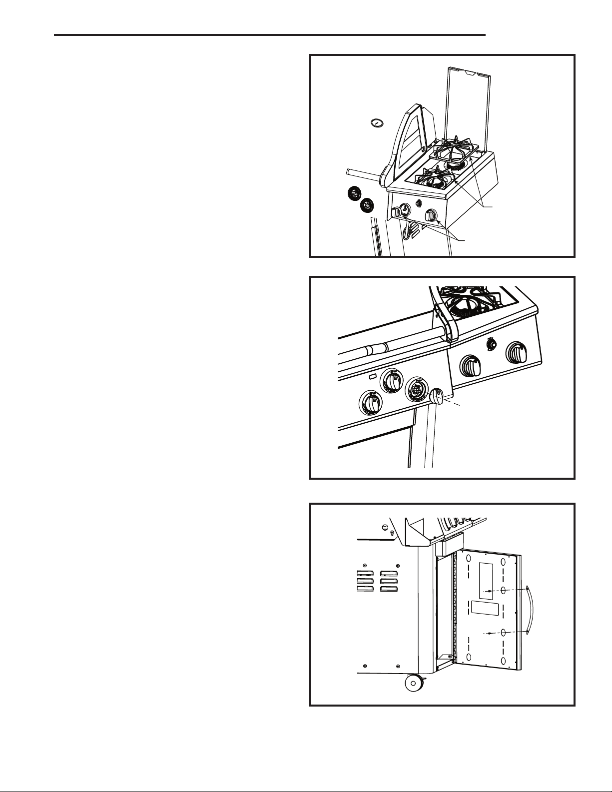
Step 8: Side Burner Grates,
Side Burner Knobs
Materials Required:
Side Burner Grate (2)
Side Burner Knob (2)
Place side burner grates in proper position.
Attach knobs.
VCS6005 Assembly
Grates Side Burner
Knobs Side Burner
Step 9: Backlit Knobs
Materials Required:
Backlit Knob (7)
Attach to the console backlit knobs as shown.
Step 10: Attach Handle to Door
Materials Required:
Handle (3)
Secure the door handles (2) to the doors by inserting two (2) screws (supplied with handles) through
the circular cutouts at the rear of the door panel and
into the handle.
Attach third handle to the pull out drawer above
the doors.
NOTE:
pending on your model.
Handles may not be exactly as shown de-
Page 5
Page 2
VCS6005 Assembly
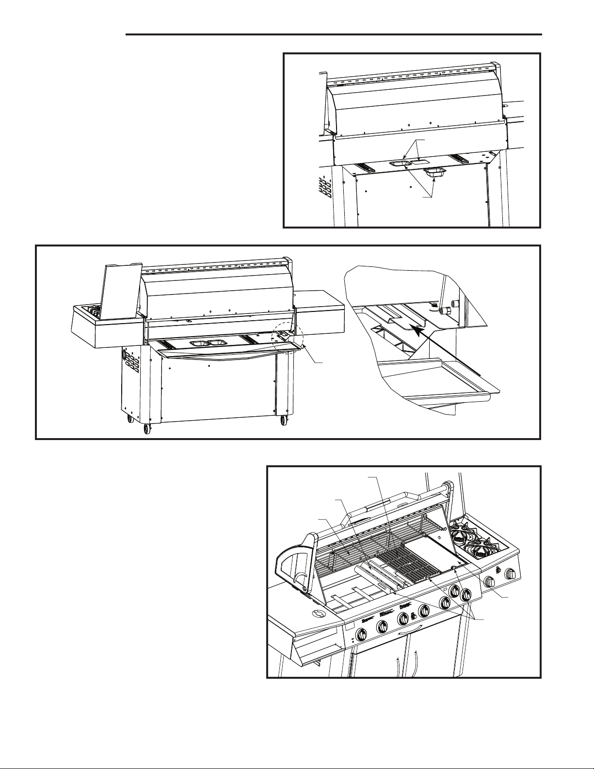
Step 11: Grease Tray and Grease Cups
Materials Required:
Grease Cups (2)
Grease Tray Assembly (1)
A. Place grease cups in position into openings in
the upper base panel area. (Fig. 11a)
B. Place grease tray in position under the com-
bustion area. (Fig. 11b)
Fig. 11b
Fig. 11a
Grease Cup Openings
Grease Cups
Detail A
Step 12: Install Internal Components
Materials Required:
Sear Plates (6)
Cooking Grates (4)
Griddle Plate (1)
Warming Rack (1)
Refer to Figure 12 for proper locations.
Place the sear plates into the base unit ensuring
the edges with the “finger holes” face the grill
front. Position the griddle plate and the cooking
grates into the base with the finger holes facing
the front. Cooking grate may be turned over to
provide a flat surface for delicate foods. Set the
warming rack into the two supports in the ends
of the rear lid.
Fig. 12
Sear Plate
Warming Rack
See Detail A
Cook Grate
Slide
Griddle
Plate
Finger Holes
at Front
Page 6
Page 3

VCS6005 Assembly
Step 13: Attach Stabilizer Bracket
Bolts
Materials Required:
Stabilizer Bracket (2)
10-24 x 1/2” Long Black Bolt (4)
Attach the stabilizer brackets to the bottom
panel.
Secure with four (4) bolts.
Stabilizers
Step 14: Install the LP Cylinder (LP Models Only)
Materials Required:
LP Gas Cylinder (Not included)
NOTE: Refer to the Userʼs Manual for the cylinder filling requirements, regulator attachments and leak testing procedures, before lighting the grill.
Insert the Propane (LP) Cylinder into the hole provided into the bottom panel.
Secure cylinder with cylinder retainer (as shown below).
Connect the cylinder to the regulator.
Step 15: Attach Utensil Hooks to Shelf
Materials Required:
(3) Utensil Hooks
Attach three (3) Utensil Hooks into the holes located
at the bottom of the shelf.
Attach to either side of grill.
Page 7
Hooks
Page 4

VCS6005 Assembly
Step 16: Side Burner / Rotisserie Control Functions
Rear Burner
Front Burner
Rotisserie
Burner and
Side Burner
Igniter
Knob Controlling
Front Burner
Knob Controlling
Rear Burner
410 Admiral Blvd. * Mississauga, Ontario * Canada L5T 2N6
phone: 1-800-227-8683
fax: 905-565-4690
www.myownbbq.com * www.vermontcastings.com
 Loading...