

Page 1
VCS4005, VCS5005/5010 ASSEMBLY PROCEDURES
Tools Required: Knife or scissors, Phillips or Robertson (square) screwdriver.
Model VCS4005 Shown
Step 1: Unpack Carton
Cut the strapping on the package, then lift off the carton cap. Remove the sleeve by lifting it straight
over the top of the Barbecue. Remove and unpack the enclosed parts boxes. Remove any protective
covering from stainless steel parts.
CAUTION:
Some parts have sharp edges - gloves are recommended when handling and assembling parts.
50003329 07/05 Rev. 5
Page 1
Page 2
VC S 4005, VCS5005/5010 Assembly
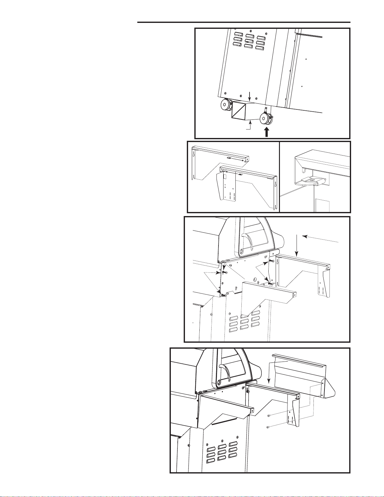
Step 2: Install Casters
Materials Required: (4) Casters.
Note: Casters may not be exactly as shown
depending on your model.
Alternately prop up each end of the grill with a
bloc
k of wood or other solid item.
Positio
botto
n the caster pin to the proper opening at the
m of the grill. Push the caster as far as
possible. Installation of the casters can also be done
by rockin
startin
g the caster in a circular motion when
g the pin into the opening.
Step 3A: Install Clip-Fasteners
Materials Required:
10-2
# C
0 lip-Fasteners (4)
e Table Brackets Left Front & Rear
Sid
e Table Bracket Right Front & Rear
Sid
A. Install the four (4) clip-fastners to the side table
bracket
s as shown, one for each side table bracket.
6” - 8”
(152 - 203mm)
Step 3B: Attach Side Table Brackets
Materials Required:
Side Table Bracket Left Front (shown)
Side Table Bracket Left Rear (shown)
Side Table Bracket Right Front
Side Table Bracket Right Rear
1/4-20 x 1-1/2
Loosely attach four (4) bolts to pre-instaled
B.
threade
Sid
tw
down.
Lef
the
fou
p 3C: Attach Condiment Tray
Ste
d inserts. (as per diagram). Attach
e Table Support Bracket Left Front over
o (2) front installed bolts, then push full
Attac
h Side Table Support Bracket
t Rear over two (2) rear installed bolts,
n push full down.
r (4) bolts. Repeat on the other side.
Materials Required:
Condiment Tray Left (shown)
Condiment Tray Right
#8-18 x 1/2" Screw (4)
" Bolt (8)
Do not yet tighten the
Bolts
Bolts
S
l
i
d
h
s
u
P
e
C. Set the condiment tray onto the front
e table support. Insert two (2) screws
sid
fro
m the back side of the side table
support
Securel
Repea
, into the condiment tray.
y tighten the two (2) bolts.
t on the other side.
Page 2
Page 3
Step 4: Attach Shelves
VC S 4005, VCS5005/5010 Assembly
Material
Shel
Shel
Seve
A.
s Required:
f Right VM-S/B (shown)
f Left VM-Solid
n (7) 10-24 x 1/2” Bolt (black)
Attach Shelf Right VM-S/B (shown) by
alignin
outsid
first
Th
gril
Repea
g it over the shelf brackets. Slide the
e of the shelf onto the ends of the brackets
, then snap it into place over the brackets.
e inside lip of the shelf will slide between the
l body and the shelf brackets.
t for the other side for Shelf Left
VM-Solid.
B.
r each shelf bracket, insert and tighten one (1)
Fo
10-24x1/2
shel
r other side shelf.
fo
" bolt into the end, underneath the
f as shown. Repeat for rear shelf bracket and
Then Snap
int
o place
Slide End
On First
Tighten the four (4) shelf bracket bolts to
C.
e the shelf brackets to the grill body.
secur
t for other side.
Repea
D. Secure Shelf Right VM-S/B (shown) to the
e with two (2) 10-24 bolts "A" and "B".
bas
Repea
t on the other side for Shelf Left
VM-Soli
d with one in the "B"(1) 10-24 bolt
location.
B. Insert Bolts
C. Tighten Bolts
Bol
t "A"
Bolt "B"
Page 3
Page 4

VCS4005, VCS5005/5010 Assembly
Page 4
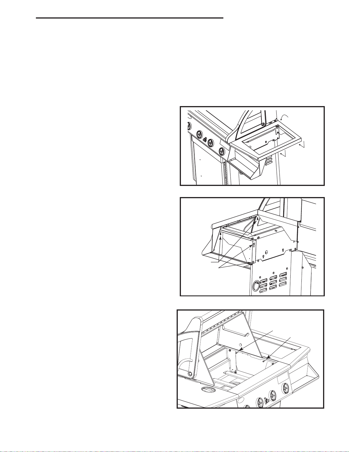
Step 5: Attach Condiment Tray to Console
Materials Required:
(2) #10-24 x 1/2” Bolt (stainless)
(2) #10-24 Nut (black)
Secure Condiment Tray to console with 10-24 x 1/2”
stainless bolt and 10-24 nut. Ensure the surfaces of the
condiment tray and console are aligned.
Tighten bolt and nut securely.
Repeat on the other side.
Bolt
Nut
Step 6: Attach Lid (S/B Single)
Materials Required:
Lid (S/B-Single)
(2) 10-24 x 3/4” (1/4” Shank)
Attach Lid (S/B-Single) to the Shelf Right
VM-S/B with two (2) 10-24 x 3/4” (1/4” shank)
bolt.
For Side Burner
Assembly, refer to fly-sheet at-
tached to S/B.
Bolt
Step 7: Attach Knobs to Valves
Materials Required:
(4) Knobs-Model VCS4005
(6) Knobs-Model VCS5005/5010
Mount required Knobs onto the valve stems.
Push the knobs securely onto the stem.
Page 5

Step 8: Attach Handle to Door
Materials Required:
(1) Handle, Model VCS4005
(3) Handles, Model VCS5005/5010
VCS4005, VCS5005/5010 Assembly
Note: Handle(s) may not be exactly as shown depending
your model of grill.
-
Secure the Door Handle(s) to the door(s) by insert
ing two (2) screws (supplied with handles) through the
circular cutouts at the rear of the door panel and into the
handle as shown.
(For Model
VCS5005/5010 - attach the third handle to
the pull out drawer above the doors.)
Step 9: Remove Packing Tape, Assemble Grease Cup
Materials Required:
(1) Grease Cup
Remove the shipping tape from the grease pan and base assembly (from inside the grill) (Fig. 9a) and from
the warming rack. For model
Install a Grease Cup into the hole in the upper base panel. (Fig. 9b) Ensure the opening in the grease pan is
positioned above the cup.
VCS5005/5010, remove the tape from the front pullout drawer.
Figure 9a
Figure 9b
Page 5
Page 6

VCS4005, VCS5005/5010 Assembly
Step 10: Install Internal Components
Materials Required:
VCS4005 - (4) Sear Plates, (3) Cooking
Grates, Warming Rack
VCS5005/5010 - (5) Sear Plates, (4) Cooking
Grates, Warming Rack
Place the Sear Plates into the base unit ensuring
the edges with the “finger holes” face the grill
front. Position the Cooking Grates into the base
with the finger holes facing the front.
be turned over to provide a flat surface for deli
These may
cate foods. Set the warming rack into the two
supports in the ends of the rear lid.
Step 11: Attach Stabilizer Bracket
Sear Plates (4/5)
Warming Rack (1)
Cooking
Grates (3/4)
Finger Hole
Materials Required:
(2) 10-24 x 1/2” Bolt (black)
(1) Stabilizer Bracket
Attach the Stabilizer Bracket to a bottom
panel as shown. Use two (2) 10-24 x 1/2” long
(black) bolts through two holes in the bottom
panel to the stabilizer bracket.
Stabilizer Bracket
Page 6
Page 7

VCS4005, VCS5005/5010 Assembly
Step 12: Install the LP Cylinder (LP Models Only)
Materials Required:
LP Gas Cylinder (Not included)
NOTE: Refer to the User?s Manual for the cylinder filling requirements, regulator attachments and leak testing procedures, before lighting the grill.
Insert the Propane (LP) Cylinder into the hole provided into the bottom panel.
Secure cylinder with cylinder retainer (as shown below).
Connect the cylinder to the regulato
r.
Step 13: Attach Utensil Hooks to Shelf
Materials Requi
red:
(3) Utensil Hooks
Attach three (3) Utensil Hooks into the holes located
at the bottom of the shelf.
Attach to either side of grill.
Page 7
Hooks
Page 8

410 Admiral Blvd. * Mississauga, Ontario * Canada L5T 2N6
phone: 1-800-227-8683
fax: 905-565-4690
www.myownbbq.com * www.vermontcastings.com
 Loading...