

Vermont Castings VCS4000, VCS5000 Assembly Procedures
VCS4000/5000 ASSEMBLY PROCEDURES
Tools Required: Knife or scissors; hammer; Phillips or #2 Robertson (square) screwdriver
Step 1: Unpack carton.
VERMONT
Castings
Box #1
Cut the strapping on the package, then lift off the carton cap. Remove the sleeve by lifting it straight over
the top of the Barbecue. Remove and unpack the enclosed parts boxes. Remove any protective covering
from stainless steel parts.
Box #4
Box #3
Box #2
Page 1
50002159 2/04 Rev.0 En
2
1
VCS4000/5000 ASSEMBLY
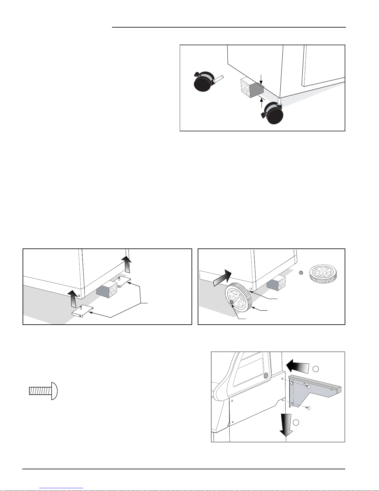
Step 2: Install casters.
Required: (2) casters
Prop up the left end of the grill with a block of
wood or other solid item.
Position a caster stem into the hole in each corner
of the bottom panel, and push as far as possible
by hand. (The holes are located approximately
Caster
6 to 8”
3” (7 cm) in from the edges.)
Fig. 2
Step 3: Install wheels.
Required: (2) wheels; (2) axle supports; (2) axle caps; (1) axle
Ensure the casters (Step 2) are in the locked position. Support the right end of the the grill as in Step 2.
Insert the two (2) axle supports into the holes in the corners of the bottom panel. Ensure the flanges with the
large hole are turned to the front and back of the grill (Fig. 3a).
Push a cap on to one end of the axle. Push a wheel onto the axle flush against the cap, with the cone-shaped
side of the wheel facing inward. Insert the axle through the holes in the axle supports. Finally slide the other
wheel into place on the axle, again with the cone-shaped side facing inward, then tap the other axle cap onto
the axle (Fig. 3b).
Axle supports
Axle cap
Axle
Wheel
Fig. 3bFig. 3a
Step 4: Attach shelf supports.
Required: (2) left shelf supports; (2) right shelf supports;
(8) 1/4–20 x 1/2” truss head bolts
(8) 1/4–20 x 1/2” Truss Head Bolt
Thread four (4) bolts halfway into the right side of the grill
base. Hook a left and a right shelf support over the bolts;
push downward on the supports, then fully tighten the bolts.
Repeat for left side.
Fig. 4
Page 2
VCS4000/5000 ASSEMBLY
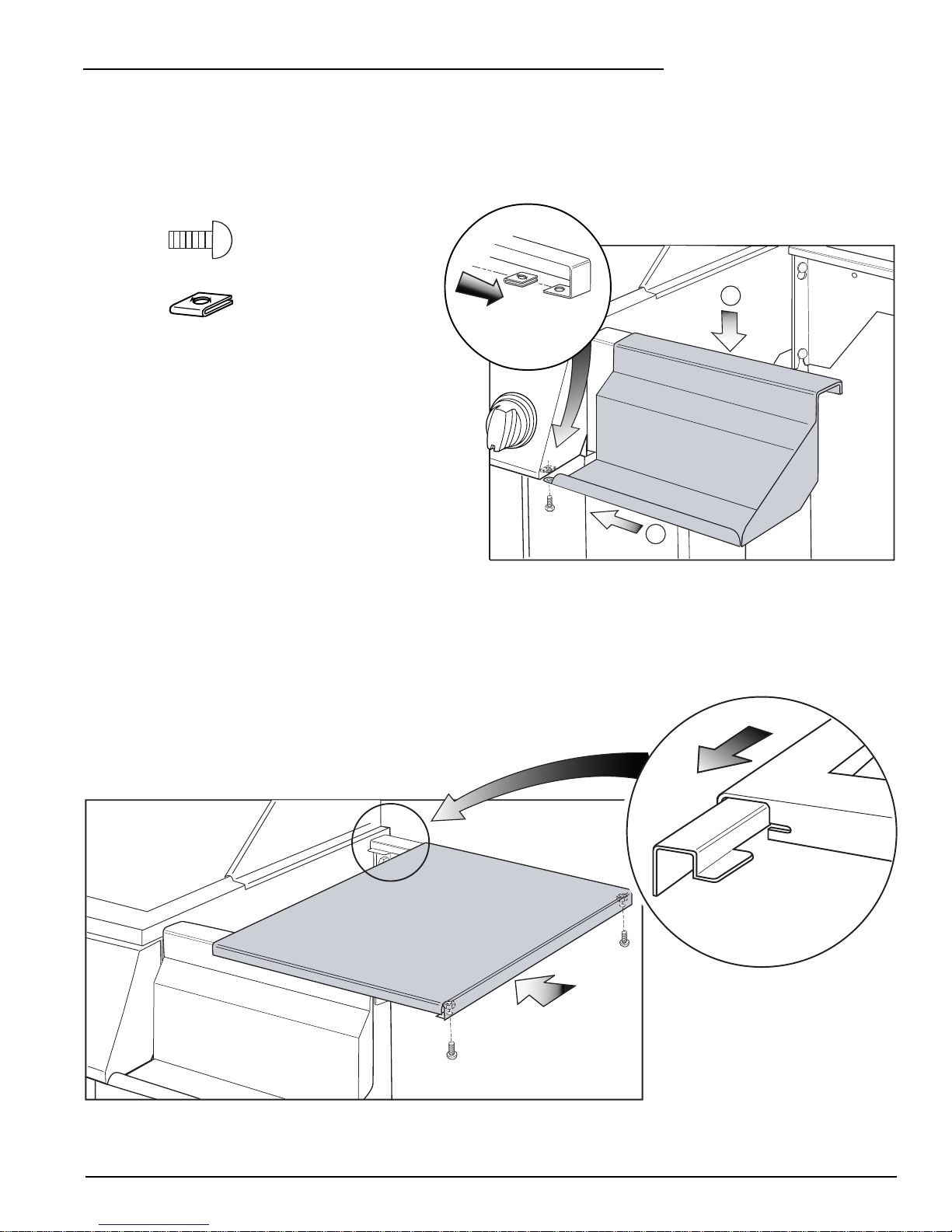
Step 5: Attach front and side shelves.
Required: (2) side shelves; (1) left and (1) right front shelf; (1) shelf insert; (6) #10–24 x 1/2” bolts;
(6) spring clip fasteners
(6) #10–24 x 1/2” Bolt
(6) Spring clip fasteners
(View rotated
90°)
Fig. 5a
1
Push a spring clip (teeth facing up) onto the inside
return flange at the end of each shelf support
(Fig. 5a), until it is centered over the hole in the
flange. Repeat for the two holes (one each corner)
in the bottom flange of the control console.
Hook the left and right front shelves over the
corresponding front shelf supports; push towards
2
the grill base. Attach to the bottom of the control
console with (1) bolt through the assembled spring
Fig. 5b
clip (Fig. 5b).
Assemble the side shelves to the shelf supports by positioning them half way over the supports, then sliding
them towards the base, while pushing down firmly on the front edge. The slots at the front edge of the shelf
should align with the tabs at the back of the shelf supports (Fig. 5c).
Tap the shelf lightly to fully engage the slot and tab if necessary
(Fig. 5d). Once aligned, fasten with two (2) bolts to the underside
of the supports through the assembled spring clips (Fig. 5c).
Slot
Tab
(View rotated 90°)
Fig. 5d
Fig. 5c
Page 3
 Loading...