

Page 1

VCS3507BI / VCS5007BI ASSEMBLY PROCEDURES
Tools Required: knife or scissors, Phillips or Robertson (square head) screwdriver.
Model VCS5007BI
Shown
PART KIT
Rotisserie Spit Rod (VCS5007BI)
Rotisserie Kit
(VCS5007BI)
Griddle Plate
Cook Grates
Step 1: Unpack Carton and Verify Contents
Use a sharp cutting tool to cut the straps on the packaging and then lift off the carton top. The sleeve
surrounding the barbecue can be removed by lifting it straight up and over the top of the unit. Next,
remove the protective plastic coverings from the metal parts
. Be careful not to scratch or damage the
finish of the metal parts when removing the protective plastic. Compare all contents to the parts list that
accompanies this assembly manual. Refer to the parts list for fastener detail.
CAUTION:
Some parts may have sharp edges; to avoid injury, wearing gloves during assembly is
strongly recommended
Page 1
50004063 11/06 Rev.0 En
Page 2
VCS3507BI / VCS5007BI Assembly
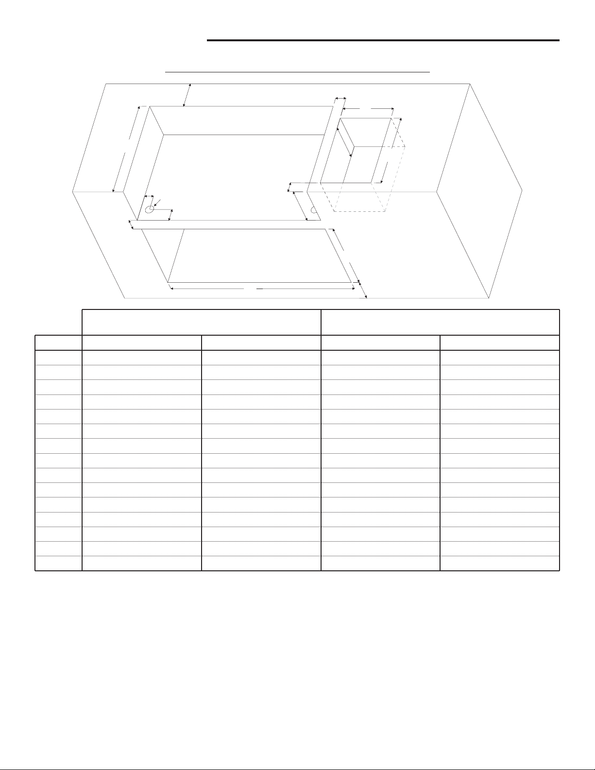
VCS3507BI / VCS5007BI FRAMING DIMENSIONS
Ref.
A
B
C
D
E
F
G
H
I
J
K
L
M
N
O
B
Fig. 2
VCS3507BI
23-3/4"
4"
2" Dia.
[50.8mm]
2 1/8"
3"
2-1/2" Min.
2-1/2" Min.
9"
31-3/8"
12"
18"
10"
18-3/4"
4" Min.
[101.6mm]
4" Min.
[101.6mm]
O
A
D
C
E
Non-Combustible Clearances
[603.3mm]
[101.6mm]
[54.0mm]
[76.2mm]
[63.5mm]
[63.5mm]
[228.6mm]
[796.9mm]
[304.8mm]
[457.2mm]
[254.0mm]
[476.3mm]
2-1/2" Min.
2-1/2" Min.
G
I
VCS5007BI
23-3/4"
2" Dia.
43-3/8"
18-3/4"
4" Min.
4" Min.
[603.3mm]
4"
[101.6mm]
[50.8mm]
2 1/8"
[54.0mm]
3"
[76.2mm]
[63.5mm]
[63.5mm]
9"
[228.6mm]
[1101.7mm]
12"
[304.8mm]
18"
[457.2mm]
10"
[254.0mm]
[476.3mm]
[101.6mm]
[101.6mm]
H
F
J
L
K
M
N
Combustible Clearances
With ZC Insulated Jacket
VCS3507BI
23-3/4"
2" Dia.
2-1/2" Min.
2-1/2" Min.
31-3/8"
18-3/4"
4" Min.
4" Min.
[603.3mm]
3"
[76.2mm]
[50.8mm]
2 1/8"
[54.0mm]
3"
[76.2mm]
[63.5mm]
[63.5mm]
10"
[254.0mm]
[796.9mm]
12"
[304.8mm]
18"
[457.2mm]
10"
[254.0mm]
[476.3mm]
[101.6mm]
[101.6mm]
VCS5007BI
23-3/4"
2" Dia.
2-1/2" Min.
2-1/2" Min.
43-3/8"
18-3/4"
4" Min.
4" Min.
[603.3mm]
3"
[76.2mm]
[50.8mm]
2 1/8"
[54.0mm]
3"
[76.2mm]
[63.5mm]
[63.5mm]
10"
[254.0mm]
[1101.7mm]
12"
[304.8mm]
18"
[457.2mm]
10"
[254.0mm]
[476.3mm]
[101.6mm]
[101.6mm]
Note: Ensure that your grill enclosure has been constructed according to the exact specifications shown in Fig.
2. If the enclosure is constructed of wood or other similar combustible materials, the use of the insulated jacket
Model VCS3500IJ or 50 is required.
VCS 00IJ
If you have an L.P. model with a 20lb cylinder stored in the enclosure, ensure that there at least two air
ventilation openings of 10sq inches 180 degrees apart and they are level with the cylinder valve. Another two
openings with the same dimensions and distance are required to be level with the base of the cylinder. For other
requirements, see section 1.7 of ANSI Z21.58-2005/CGA 1.62005 American National Standard/ Canadian Gas
Association Standard for outdoor cooking gas appliances.
Page 2
Page 3

VCS3507BI / VCS5007BI Assembly
Step 3: Assemble Fascia Brackets
Parts Required:
(1) Main Grill Unit
(1) Left Fascia Bracket
(1) Right Fascia Bracket
(4) #10 x 1/2” Bolts
(4) #10 Lock Nuts
Prop up the front of the Grill Unit on a 2” or 3” block of wood or some other similar item. Remove the two (2)
1/4”-20 x 3/8” bolts located at the top-right corner on the left and right side of the base assembly and loosen the
two (2) front 1/4”-20 x 3/8” bolts as shown in the adjacent diagram.
Next: Attach the Right Fascia Bracket to the grill base by aligning the holes over the loosened bolts and gently
pushing down on the Fascia until the bolts settle into the grooves.
Note:
Ensure the bottom of the flanges on the Left and Right Fascia Brackets slides between the flange of the
bottom cover and the console.
Then secure the rear of the Brackets to the Grill Unit using the 1/4”-20 x 3/8” bolt you initially removed. Secure
the Brackets to the lower-front of the Grill Body by inserting two (2) #10 x 1/2” Bolts and two (2) #10 nuts as
shown in the adjacent diagram.
1/4-20 x 3/8” Bolt
(already assembled)
Fig. 3
#10 Bolts
1/4-20 x 3/8” Bolt
(remove half way
from base assembly)
Page 3
Page 4

VCS3507BI / VCS5007BI Assembly
Step 4: Assemble the Rear Panel
Parts Required:
(1) Rear Panel
(1) Back Flange
(5) Self-Tapping Screws
Attach the Back Flange of the Rear
Panel to the Grill Base with
three (3) Self-Tapping screws.
Next: Fasten the ends of the
Rear Panel to the Left and
Right Fascia Brackets with
(2) Self-Tapping screws.
Fig. 4
Page 4
Page 5

Step 5: Assemble the Grease Tray Front and Handle
Parts Required:
(1) Grease Tray Front
(1) Handle (with screws)
(2) #10 Bolts
(2) #10 Nuts
Remove the Grease Tray from the front of the Grill
Base (Below the Control Console). Remove the
protective plastic from the Grease Tray Front
and attach it to the front lip of the Grease
Tray with the two (2) #10 Bolts and
tighten using the two (2) #10 Nuts.
VCS3507BI / VCS5007BI Assembly
Next: Attach the handle to the tray
with the two (2) screws supplied
with the handle.
Note:
Do not reinsert the Grease Tray
into the Grill Base at this time.
Service Note:
Due to the shallow depth of
the grease tray, ensure it is cleaned frequently
to avoid a possible “Grease Fire”.
Fig. 5
Page 5
Page 6

VCS3507BI / VCS5007BI Assembly
Step 6: Assemble the Grill Unit to the Enclosure
Note:
This step should be performed by two (2) persons wearing gloves.
Before positioning the Grill Unit into the prepared enclosure or insulated jacket, depending on available access,
it may be necessary to temporarily disconnect the LP regulator or 12 ft. Natural Gas Hose from the Steel Flex
Line.
Carefully position the Grill Unit into the opening from the front and raised slightly, while ensuring the gas feed
tubing is fed through the hole provided in the bottom of the enclosure opening. Push the unit back into its final
position and check for proper fit.
Next: Reattach the LP Regulator or hose if it was removed and check all connections for leaks. Reinsert the
Grease Tray into its place.
Caution:
The end of the Steel Flex Line should be clamped to the surrounding structure to prevent excessive
movement.
Caution:
Do not turn on the grill until after performing a leak check at all connection points and fittings. Use a
spray solution of 50% dish soap and 50% water onto all connection points and fittings. Formation of bubbles
indicates air leaks.
Page 6
Fig. 6
Page 7

Step 7: Install Internal Components and Knobs
Parts Required:
VCS3506
- (3) Sear Plates, (2) Cooking Grates, (1) Warming Rack, (4) Knobs
VCS3507BI / VCS5007BI Assembly
VCS5006
- (5) Sear Plates, (4) Cooking Grates, (1) Warming Rack, (6) Knobs
Carefully place each of the Sear plates side by side inside the barbecue by making sure the semicircular finger
groove is facing toward the front of the grill. Do the same using the cooking grates, making sure the finger
groove is facing toward the front of the grill. Next set the warming rack into the supports located on either side
of the rear lid.
Next: Align the knobs on the valve stems and push inward until the knob sits snugly on the stem.
Warming Rack
Griddle
Plate
Cooking
Grids
Indicator Faces Up
Sear
Plates
Finger Hole
Page 7
Page 8

CFM Corporation
410 Admiral Boulevard
Mississauga, Ontario L5T 2N6 Canada
(800) 668-5323
www.cfmcorp.com
Service Note: If you are experiencing difficulties or are dissatisfied with your purchase, please contact CFM at
the telephone number listed above prior to returning your grill to the store.
Page 8
 Loading...