

Page 1
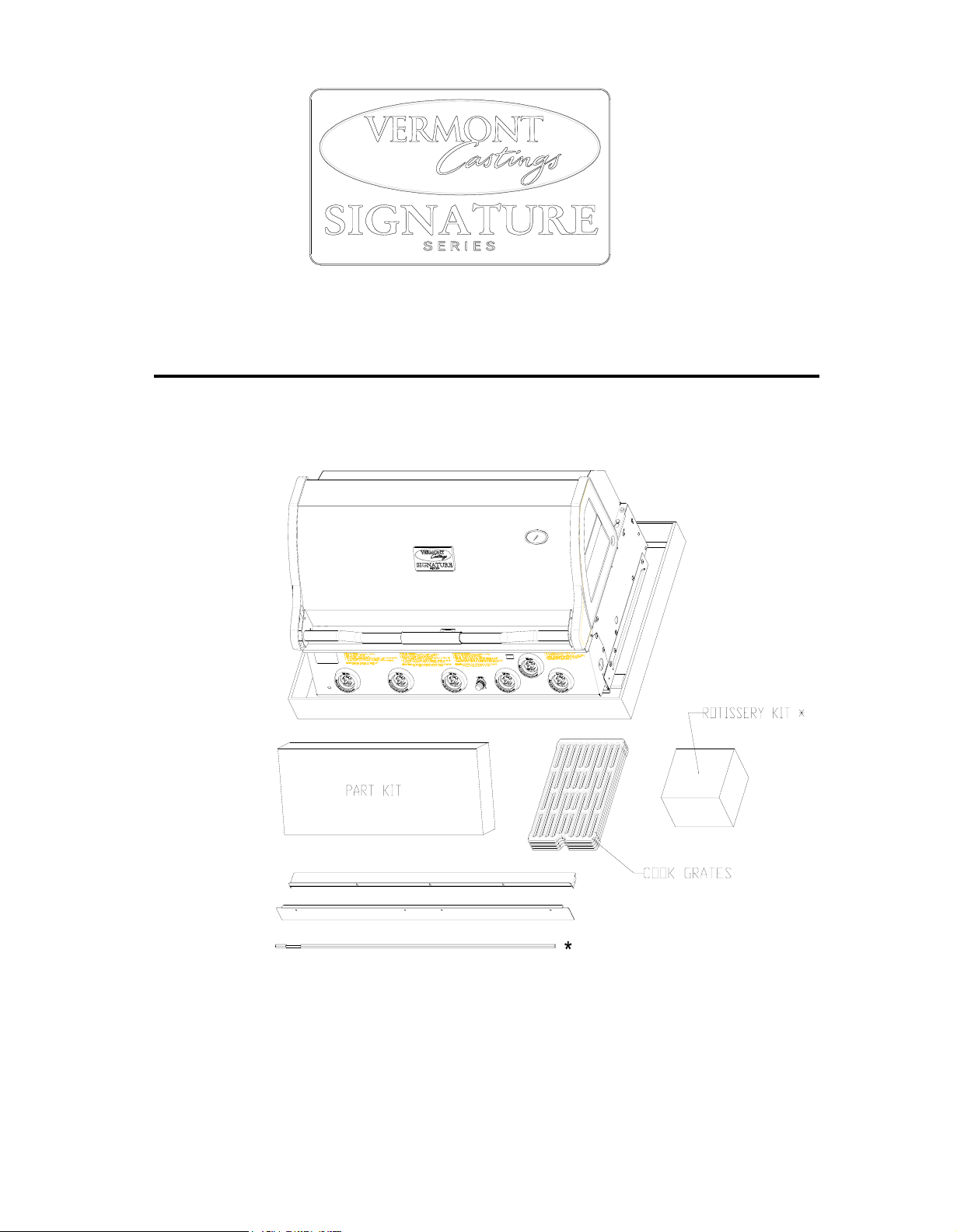
VCS3505BI/VCS5005BI ASSEMBLY PROCEDURES
Tools Required: Knife or Scissors, Philips or Robertson Screwdriver:
Step 1: Unpack carton.
* MODEL VCS5005BI
Fig- 1
Use the knife or scissors to cut the strapping on the package, and then lift off the cardboard cap. Remove the
cardboard sleeve by lifting it straight over the top of the barbecue. Remove the enclosed boxes of parts and
unpack the enclosed parts. Remove any protective covering from stainless steel parts.
1
50003225 03/2005 Rev. 1 Eng.
Page 2
VCS3505BI/VCS5005BI ASSEMBLY
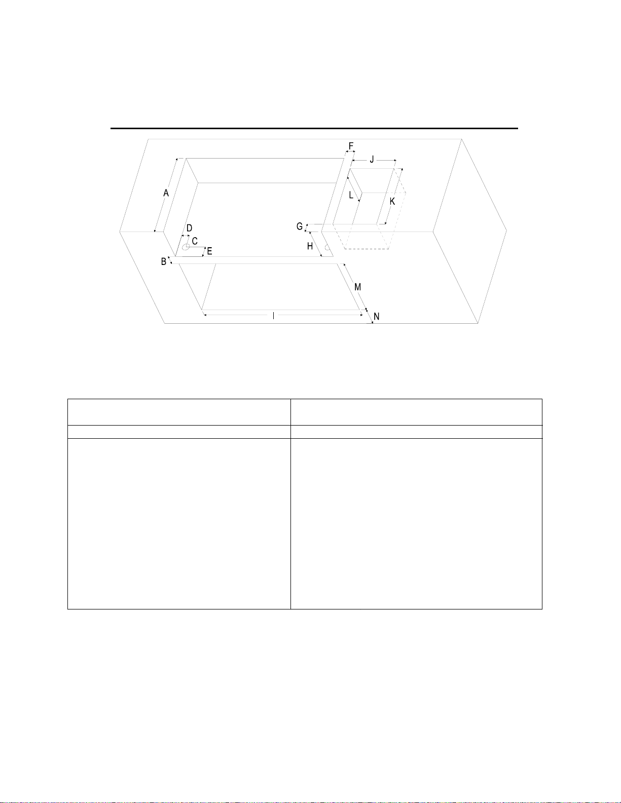
VCS3505BI/VCS5005BI FRAMING DIMENSIONS
______________________________________________________
Fig- 2
ALL DIMENSIONS ARE IN INCHES
CLEARANCES
Combustible Clearances
Non-Combustible Clearances With ZC Insulated Jacket
Reference VCS3500BI VCS5005BI Reference VCS3500BI VCS5005BI
A 23 ¾” 23 ¾” A 23 ¾" 23 ¾"
B 4" 4" B 3" 3"
C 2" Dia. 2" Dia. C 2" Dia. 2" Dia.
D 2 1/8" 2 1/8" D 2 1/8" 2 1/8"
E 3" 3" E 3" 3"
F 2 ½” Min. 2 ½” Min. F 2 ½” Min. 2 ½” Min.
G 2 ½”Min. 2 ½” Min. G 2 ½” Min. 2 ½” Min.
H 9" 9" H 10" 10"
I 31 3/8" 43 3/8" I 31 3/8" 43 3/8"
J 12" 12" J 12" 12"
K 18" 18" K 18" 18"
L 10" 10" L 10" 10"
M 16" 18 ¾” M 16" 18 ¾”
N 4" Min. 4" Min. N 4" Min. 4" Min.
Note: Ensure that your grill enclosure has been constructed to the dimensions shown in Fig 2. If the
enclosure is constructed of wood or other similar combustible materials, the use of the insulated jacket,
Model VCIJ35A or VCIJ50A, is required.
you have an L.P. model with a 20 lb. cylinder stored in the enclosure, ensure that there are a least two air
If
ventilation openings of 10 sq. inches, 180 deg. apart, at the cylinder valve level, and two more at the
cylinder base level. For other requirements, see section 1.7 of ANSI Z21.58a-1998/CGA 1.6a-M98American National Standard/Canadian Gas Association Standard for outdoor cooking gas appliances.
2
50003225 03/2005 Rev. 1 Eng.
Page 3

VCS3505BI/VCS5005BI ASSEMBLY
______________________________________________________
Step 2: Assemble Fascia Brackets:
Required: Main Grill unit, Left Fascia Bracket, Right Fascia Bracket, (4) # 10 x 1/2” Bolts, (4) # 10 Lock
Nuts (in provided hardware bag).
the front of the grill unit up 2 to 3 inches with a block of wood of other similar item. Carefully remove the
Tilt
protective plastic from the 2 fascia brackets, and the rear panel. Remove the (2) 1/4"-20 x 3/8” bolts from the
top back of the left and right sides of the base assembly, and loosen the (2) front 1/4"-20 x 3/8” bolts as
shown.
Attach the right hand fascia bracket to the
grill base as shown. The mounting slot
at
the front of the bracket slides over
and down the loosened front bolt.
The
rear is attached with the
1/4”- 20 x 3/8” bolt removed
previously. Also attach the
lower front of the bracket
with (2) # 10 bolts and
(2) # 10 nuts supplied.
Repeat for the left side
Fascia bracket (Fig- 3).
Fig- 3
Step 3: Assemble Rear Panel:
Required: Rear Panel, (5) Self-Tapping Screws
Fasten the back flange of the rear panel to the grill base
With (3) self-tapping screws. Fasten the ends
of the rear panel to the flanges on the
left and right fascia brackets with
self-tapping screws
(2)
(Fig-
4).
Fig- 4
3
50003225 03/2005 Rev. 1 Eng.
Page 4

VCS3505BI/VCS5005BI ASSEMBLY
______________________________________________________
Step 4: Assemble Grease Tray Front and Handle:
Required: Grease Tray Front, Handle and Screws, (2) # 10 Bolts, (2) # 10 Nuts
Remove the grease tray from the front of the unit (Below the control console).
Remove the protective plastic from the front panel and
att
ach to the front lip of the grease tray with (2) bolts
and
nuts. Attach the handle to the tray with the
(2) bolts supplied with the handle (Fig- 5).
Do
not reassemble the grease tray into
the
unit at this time.
NOTE: Due to the shallow depth
of the grease tray, ensure it is cleaned
often to avoid a possible
“Grease Fire”.
Fig- 5
Step 5: Assemble the Grill Unit to the Enclosure:
Note: This step should be performed by 2 persons wearing gloves.
fore positioning the grill unit into the prepared enclosure or insulated jacket, it may be necessary to
Be
temporarily disconnect the LP regulator or 12 ft. natural gas hose from the steel flex line, depending on
available access.
Care
fully position the grill unit into the opening from the front and raised slightly, while ensuring the gas feed
tubing is fed through the hole provided in the bottom of the enclosure opening. Push the unit back into its final
position, and check for proper fit.
Reattach the LP regulator or hose if removed, and leak check all connections.
Reinst
The
all the grease tray assembly into position.
end of the steel flex line should be clamped to the surround structure to prevent excessive movement.
4
50003225 03/2005 Rev. 1Eng.
Page 5

VCS3505BI/VCS5005BI ASSEMBLY
______________________________________________________
Step 6: Install Sear Plates, Cooking Grates, Warming Rack, and Knobs:
Required: (3) (5*) Sear Plates, (2) (4*) Cooking Grates, (1) Warming Rack, (4) (6*) Knobs:
Place the sear plates into the barbecue, ensuring the edge with the finger hole faces the front.
Position the cooking grates in the base unit with the finger holes to the front. These may be turned over to
provide a flat surface for delicate foods.
Set the warming rack into the two supports in the ends of the rear lid.
Insert knobs into the valves-stem as shown (note that the indicator on the knob must face up while installing).
* Model VCS5005BI
Fig- 6
5
50003225 03/2005 Rev. 1 Eng.
Page 6

410 Admiral Blvd. * Mississauga, Ontario * Canada L5T 2N6
phone: 1-800-227-8683
fax: 905-565-4690
www.myownbbq.com * www.vermontcastings.com
50003225 03/2005 Rev. 1 Eng.
 Loading...