

Vermont Castings VCS325 Series, VCS425 Series, VCS525Series Assembly Instruction Manual
VCS325 Series, VCS425 Series, VCS525
Series Assembly Instructions
VCS525
VCS425
VCS325
Tools Required: Knife or scissors, Phillips or Robertson (square head) screwdriver or ratchet. The use of a manual
screwdriver is strongly recommended. A power drill may cause damage to the unit or stripping of the protective
coating.
WARNING! Some parts may have sharp edges. To avoid injury, wearing gloves during
assembly, lifting or moving is recommended. Protective eyewear and long sleeves are also
strongly recommended.
CAUTION: The assembly of this grill requires two (2) people. Be careful when opening boxes packed inside the grill to avoid scratching the stainless steel parts.
CAUTION: This grill is intended ONL Y to be used as a cart model, this grill cannot be built into an enclosure.
NOTE: Remove the protective plastic coating from the stainless steel. Failure to do so will void the warranty.
30007228 10/14 Rev. 1 En
VCS325/425/525 Series Assembly
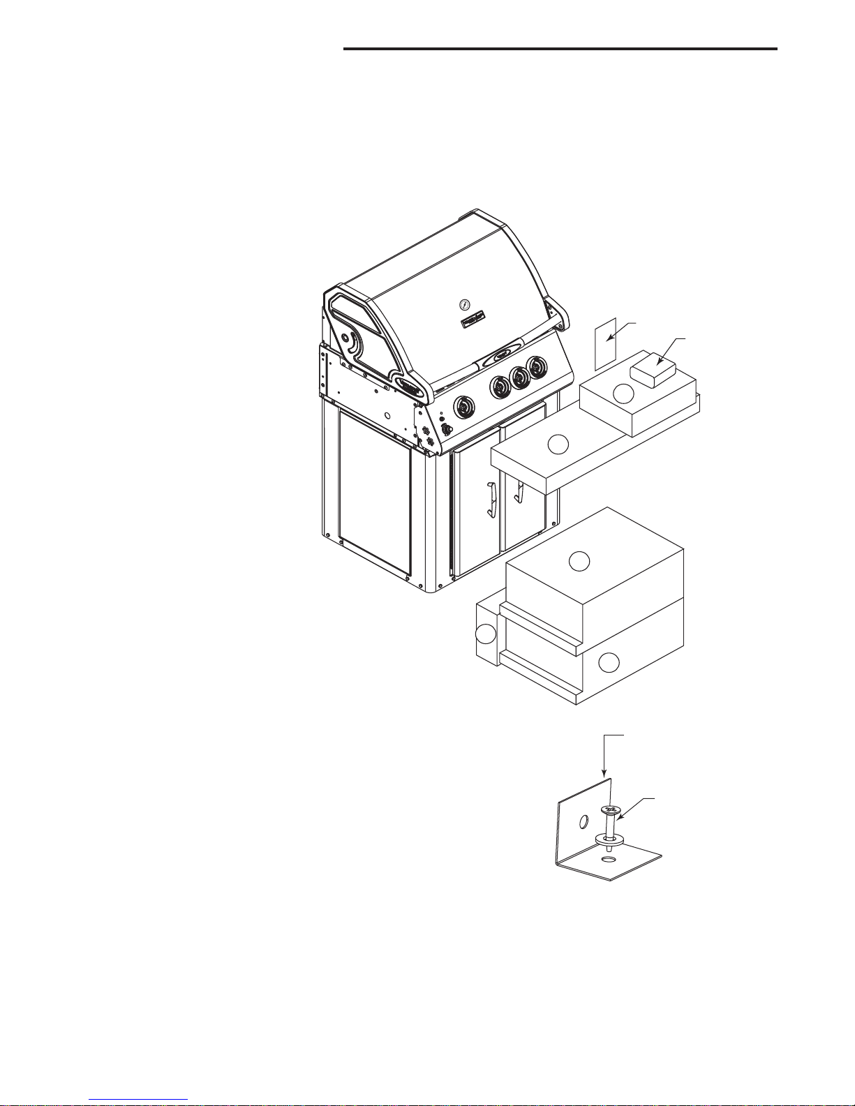
Step 1: Unpack Carton and Verify Contents
Remove one (1) screw from each lower corner that fastens the hold down bracket to the barbecue. Retain
these screws. Remove the wood screws that fasten the hold down bracket to the pallet. Discard four (4)
wood screws and four (4) hold down brackets. Replace one (1) screw in each corner where hold down
bracket was removed.
VCS325 Series Carton Contents
Box 1 (30006888)
Grease Pan
Grease Cup
Warming Rack
Bracket, Spit Rod Storage (2)
Spit Rod (26")
Box 2 (30007238)
Condiment Tray Left
Condiment Tray Right
Towel Bar (2)
Utensil Hook (3)
Heat Plate (3)
VCS325
1
1
Bag 1
VC Grill Cover
2
Box 3
Cook Grates (2) (30006527)
Box 4
(LP - 30006872)
(NG - 30006874)
Shelf Right Assembly
Shelf Right Assembly Cover Side Burner
Side Burner Assembly
Box 5 (20304920)
Shelf Left Assembly
Caster Swivel (3)
Caster Swivel w/ Brakes (1)
Anti-tip Support
Rotisserie Kit
Light kit
Bag 1 Instruction Package (30007233)
User’s Guide
Assembly Instructions
Parts List
Paper Match Holder Assy.
Battery ‘AAA’
Lid Bumper Set
Hardware Bag Side Shelves
Hardware Bag – Anti-tip Support
Hardware Bag, Casters
4
3
5
Hold Down
Bracket
Wood
Screw
CAUTION: Be careful when opening boxes
packed inside the grill to avoid scratching the
stainless steel parts.
2
30007228
VCS325/425/525 Series Assembly
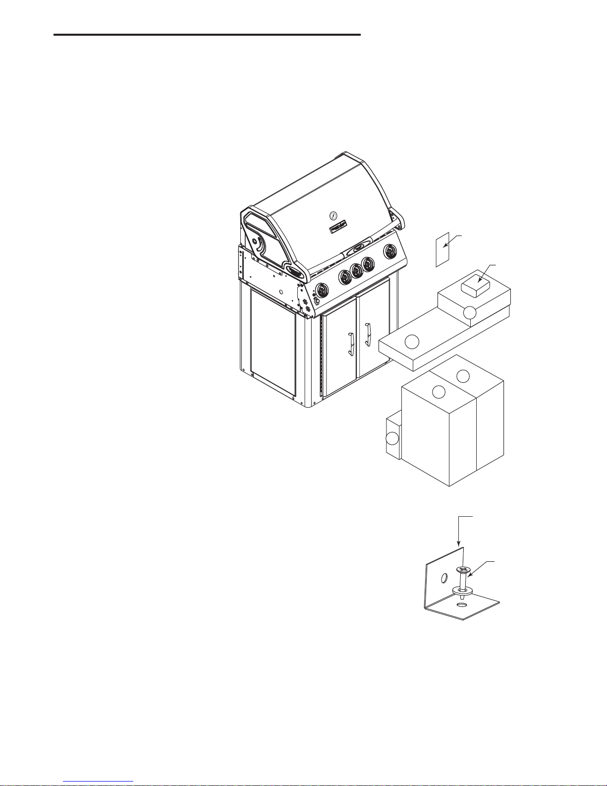
Step 1: Unpack Carton and Verify Contents
Remove one (1) screw from each lower corner that fastens the hold down bracket to the barbecue. Retain
these screws. Remove the wood screws that fasten the hold down bracket to the pallet. Discard four (4) wood
screws and four (4) hold down brackets. Replace one (1) screw in each corner where hold down bracket was
removed.
VCS425 Series Carton Contents
Box 1 (30005770)
Grease Pan
Warming Rack
Grease Cup
Bracket Spit Rod Storage (2)
Spit Rod 29”
Box 2 (20304957)
Condiment Tray Left
Condiment Tray Right
Towel Bar (2)
Utensil Hook (3)
Heat Plates (4)
VCS425
Bag 1
VC Grill Cover
2
Box 3 (30006525)
Cook Grates (3)
Box 4
(LP - 30006872)
(NG - 30006874)
Shelf Right Assembly
Shelf Right Assembly Cover Side Burner
Side Burner Assembly
Box 5 (20304920)
Shelf Left Assembly
Kit VC Light
Rotisserie Kit
Caster Swivel (3)
Caster Swivel w/ Brakes (1)
Anti-tip Support
Bag 1 Instruction Package (30007232)
User’s Guide
Assembly Instructions
Parts List
Paper Match Holder Assy.
Battery ‘AA’
Lid Bumper Set
Hardware Bag Side Shelves
Hardware Bag Anti-tip Support
Hardware Bag, Casters
1
5
4
3
Hold Down
Bracket
Wood
Screw
CAUTION: Be careful when opening boxes
packed inside the grill to avoid scratching the
stainless steel parts.
30007228
3
VCS325/425/525 Series Assembly
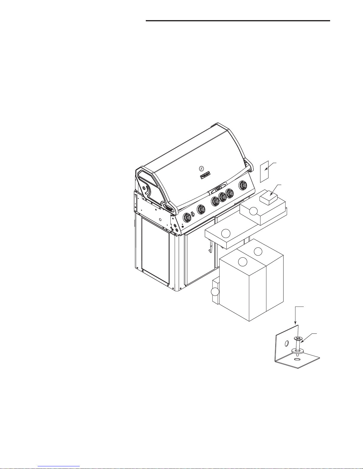
Step 1: Unpack Carton and Verify Contents
Remove one (1) screw from each lower corner that fastens the hold down bracket to the barbecue. Retain
these screws. Remove the wood screws that fasten the hold down bracket to the pallet. Discard four (4) wood
screws and four (4) hold down brackets. Replace one (1) screw in each corner where hold down bracket was
removed.
Use a sharp cutting tool to cut the straps on the packaging and then lift off the carton top. Remove the box
on the top. The sleeve surrounding the barbecue can be removed by lifting it straight up and over the top of
the unit. Compare all contents to the parts list and the carton content lists below. Refer to the parts list for
fastener detail.
VCS525 Series Carton Contents
Box 1 (20302911)
Grease Pan
Grease Cup
Warming Rack
Spit Rod
Bracket Spit Rod Storage (2)
Box 2 (20304956)
Condiment Tray Left
Condiment Tray Right
Towel Bar (2)
Utensil Hook (3)
Heat Plate (5)
VCS525
Bag 1
VC Grill Cover
2
Box 3 (30006526)
Cook Grate (4)
Box 4
(LP - 30006872)
(NG - 30006874)
Shelf Right Assembly
Cover Side Burner
Side Burner Assembly LP
Side Burner Cook Grate
Box 5 (20304920)
Shelf Left Assembly
Kit VC Light
Rotisseries Motor Kit
Caster Swivel (3)
Caster Swivel w/ Brakes (1)
Anti-tip Support
Bag 1: Instruction Package (30007232)
User’s Guide
Assembly Instructions
Parts List
Paper Match Holder Assy.
Battery “AA”
Lid Bumper Set
Hardware Bag Side Shelves
Hardware Bag Anti-tip Support
Hardware Bag, Casters
1
4
5
3
Hold Down
Bracket
Wood
Screw
CAUTION: Be careful when opening boxes packed
inside the grill to avoid scratching the stainless steel
parts.
4
30007228
VCS325/425/525 Series Assembly
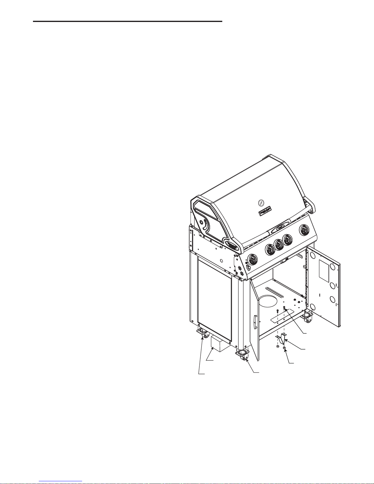
Step 2: Install the Casters and Anti-tip Support
This step requires 2 people.
Parts Required:
(4) Casters (1 with brake; 3 without brake) (1) Anti-tip Support
(1) Block (not included) (2) 10-24 Truss Head Screws
(16) 1/4-20 Flange Nut (50001176) (2) 10-24 Hex Nuts
Figure 1
NOTE: Casters (wheels) may differ from those shown in the illustration depending on the model you purchased.
Select a side to begin installing the casters. Place a block of wood, thick telephone book or anything else
available - approximately 6 inches thick - under the side to support the weight of the barbecue. Insert the four
(4) bolts attached on the casters into their respective holes located on the bottom, near the front. If you have
any diffi culty snapping them into place, try rotating the casters in a circular motion.
As one person holds the front caster in place, the
other opens the front door and installs four (4)
fl ange nuts. Tighten the fl ange nuts on the front
caster. Repeat this process with the rear caster.
When both casters are in place on one side, repeat the same procedure on the opposite side.
After installing the casters, the corner supports
must be repositioned. Do this by removing the
two (2) screws securing the support, rotate the
support 180° and reinstall using the same screws.
(Fig. 1a)
After installing the casters, install the anti-tip support. Position the support under the bottom, slightly to the rear where the front doors meet. Fasten
the support using the 10-24 screws and hex nuts
supplied.
30007228
B511
Blocking
Rear Caster
w/Brake
Figure 1
10-24 Truss Head
Screw
Anti-tip Support
10-24 Hex Nut
Front Caster
without Brake
NOTE: Tank pull out not shown.
5
VCS325/425/525 Series Assembly
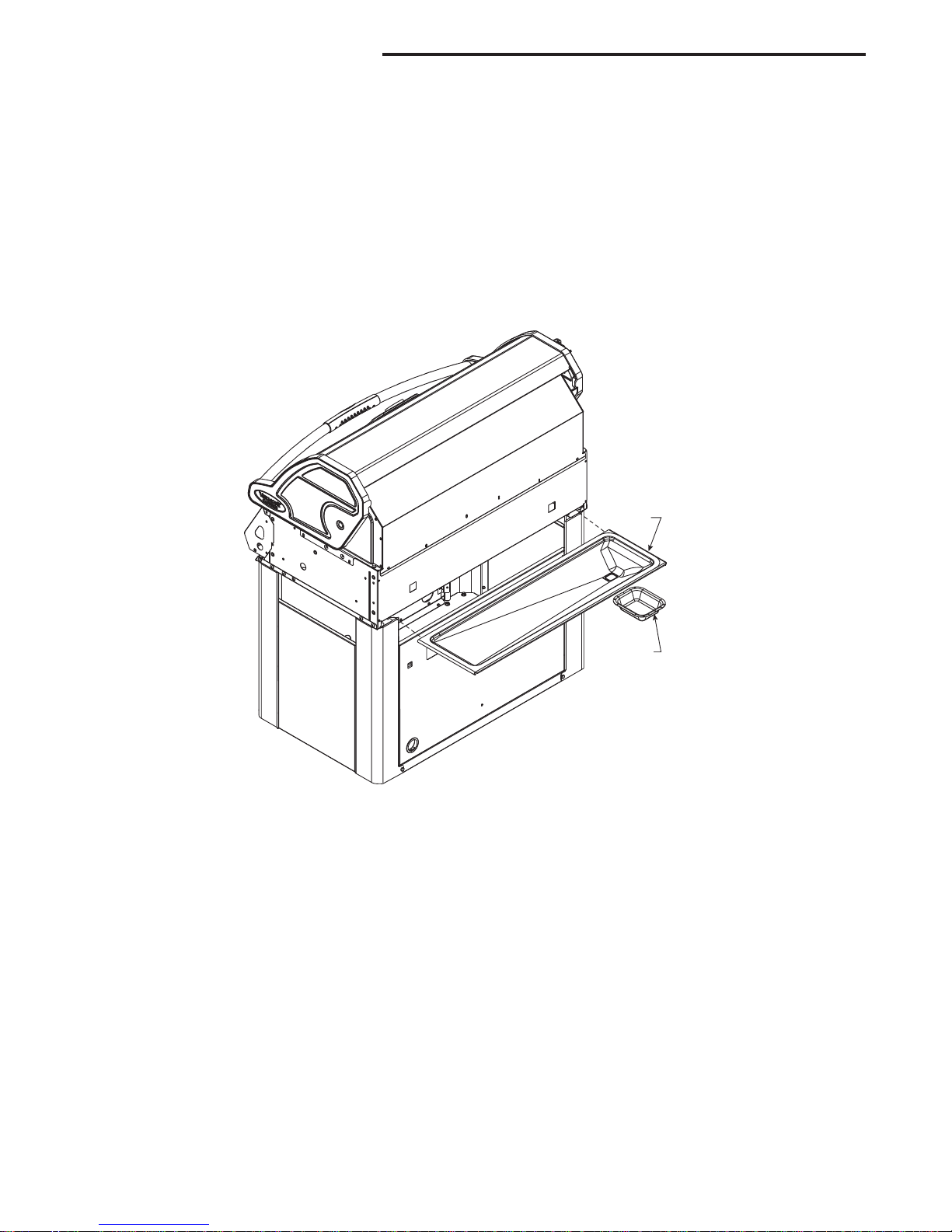
Step 3: Grease Pan / Grease Cup Installation
Parts Required:
(1) Grease Tray
(1) Grease Cup
Figure 2
Install grease pan from back side of unit. NOTE: Be sure the grease tray is positioned with the opening in the
bottom of the grease tray located over the grease cup.
Place grease cup into grease cup holder attached to bottom of left brace support.
Figure 2
Grease
Tray
B389
Grease
Cup
6
30007228
 Loading...