

Vermont Castings vc75, vc75a Assembly Procedures
VC50/75A ASSEMBLY
VC50/75A ASSEMBL Y PROCEDURES
Tools Required: Knife or Scissors, Hammer, 7/16” (11 mm) wrench/ratchet or an adjustable wrench,
Philips or Robertson screwdriver.
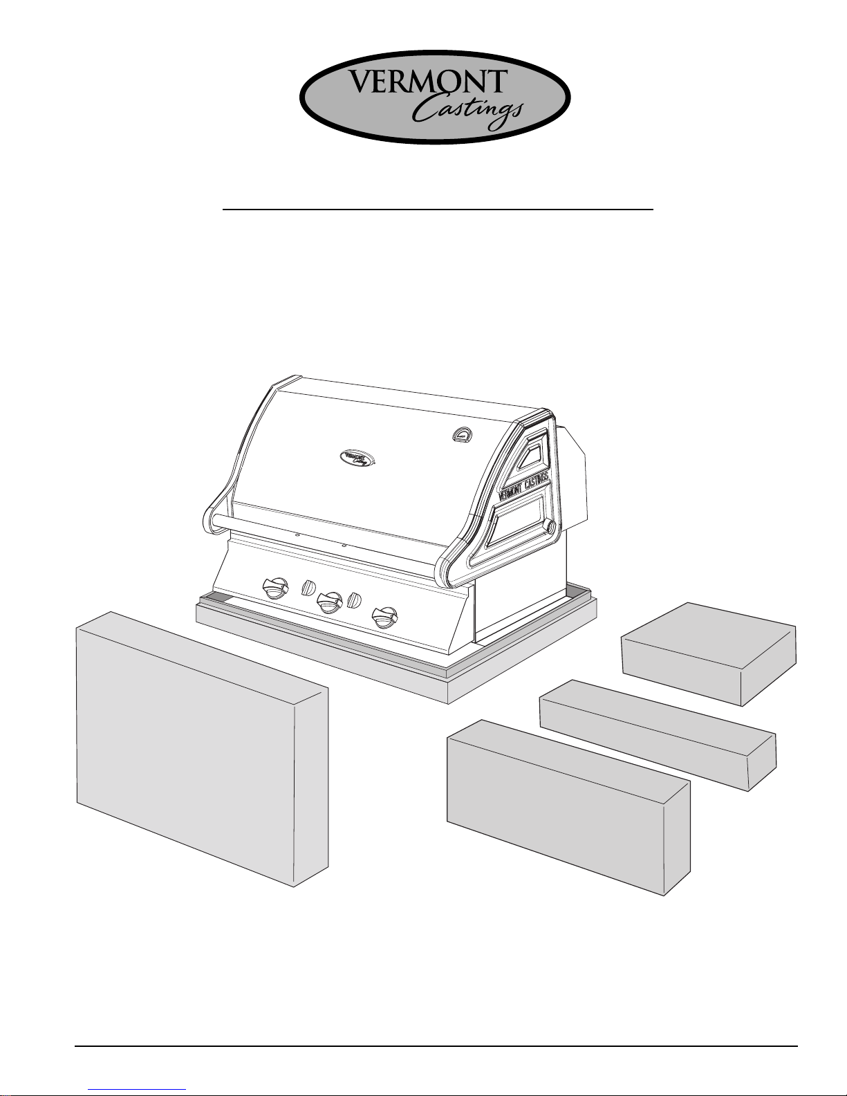
Step 1: Unpack carton
Box
#
4
Box
Use the knife or scissors to cut the strapping on the package then lift off the cardboard cap.
Remove the cardboard sleeve by lifting it straight over top of the barbecue. Check the 4 enclosed
parts kits, 3 boxes outside the grill, and 1 box inside, against the parts list (Appendix A) to ensure
that no parts are missing.
#
1
Box
#
3
Box
Page 1
#
2
VC50/75A ASSEMBLY
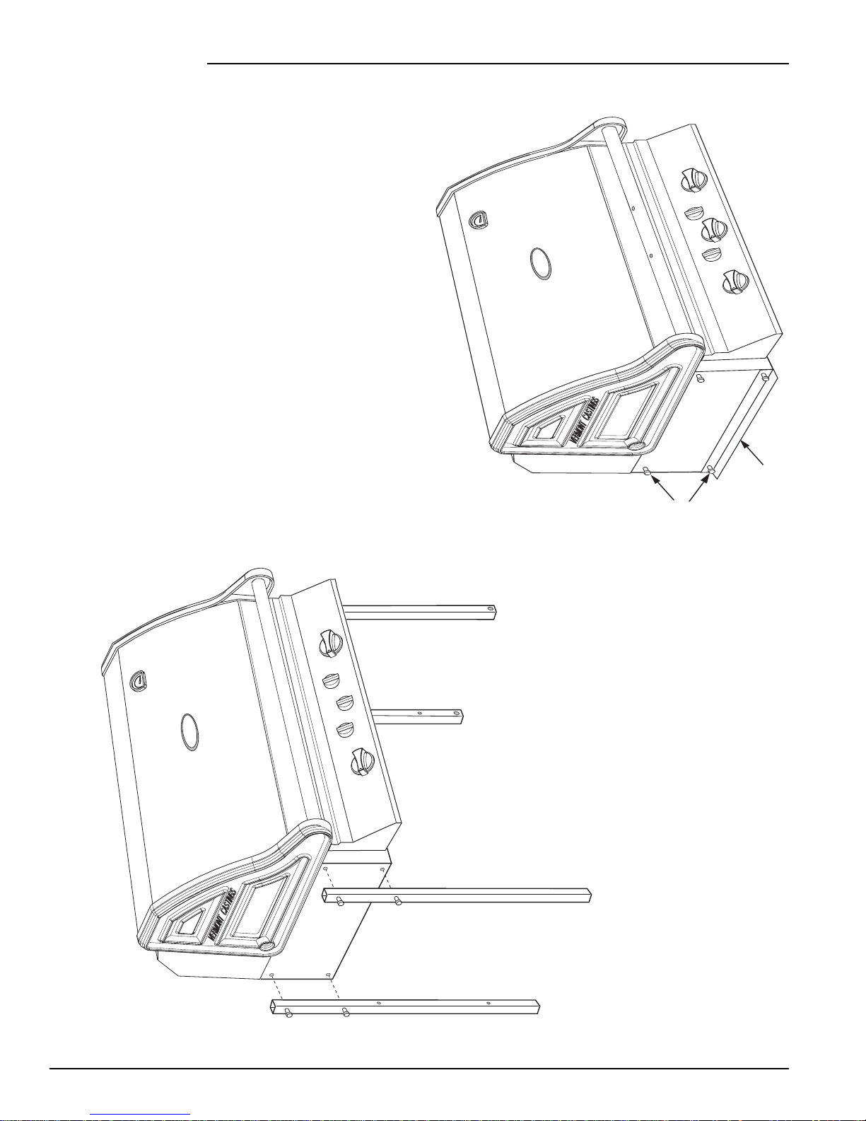
Step 2: Assemble Legs
Required: The Main Grill Unit, (2) Right Legs,
(2) Left Legs, (8) 1/4” x 1-3/4” Hex Head Bolts.
Carefully remove the grill unit from the carton bottom,
and lay it on its back (use the flattened carton cap as a
protective surface). This is best performed with 2
people (use of gloves is recommended). Ensure the
front lid does not fall open while moving the unit.
Allow the lid to rest partially open once the unit is on
its back.
Remove and discard the 2 shipping brackets and bolts
from the bottom of the unit by removing the 4 bolts
holding them to the base. Also remove and discard the
4 bolts above these (fig 2A).Attach the two right legs
(with the large hole at the bottom end) to the right side
of the base using (4) 1/4” x 1-3/4” bolts. Ensure that the
sides with the 2 small holes, about 6 inches from each
end, are facing inwards. Tighten the bolts only finger tight
(Fig 2B). Repeat for the left legs.
astings
C
VERMONT
Shipping
Brackets
Remove
Bolts
astings
C
VERMONT
Fig. 2A
Fig. 2B
Page 2
VC50/75A ASSEMBLY
VERMONTVERMONT
C
astings
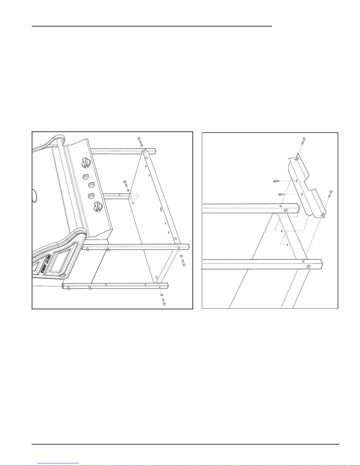
Step 3: Assemble Bottom
Required: Bottom Pan, (4) 1/4” x 1-3/4” Hex Head Bolts, (4) 1/4 ” Hex Nuts, (4) 1/4” Washers, (for propane models only – the Lower Tank Bracket, (2) 1/2” self tap screws, (2) 1/4” Washers only.
Assemble the Bottom Pan to the legs with 4 bolts and nuts as shown. Ensure the side with 5 holes at the
edge is facing up towards the front of the grill (Fig 3A). For propane models, also attach the lower tank
bracket to the right end, no washers are required (Fig 3B). Assemble the top flange of the lower tank
bracket to the bottom pan with (2) self tap screws. Tighten the fasteners.
Fig. 3A
Fig. 3B
Page 3
VC50/75A ASSEMBLY
Cap
Wheel
Axle
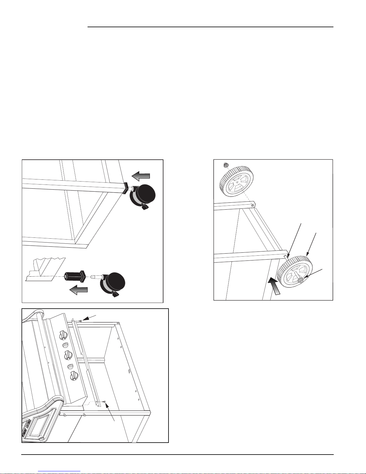
Step 4: Assemble casters, wheels and upper door support
Required: (2) Caster Inserts, (2) Casters, (2) Wheels, Axle, (2) Axle Caps, Upper Door Support, (2) 1/2” self
tap screws.
Place a caster insert into the bottom of each left leg, and lightly tap into place with a hammer. Snap the
casters into the inserts (Fig 4A).
Tap an axle cap onto 1 end of the axle. Slide a wheel onto the axle flush against the cap. Insert the end of the
axle down through the large holes at the bottom of the right legs. Lift the bottom of the legs up enough to
place the other wheel onto the axle (Fig 4B).
Install the upper door support to the front corners of the grill base with 2 self-tapping screws (Fig 4C).
Carefully lift the grill assembly off its back onto the wheels and casters (2 people). Tap the other axle cap
onto the axle.
Fig. 4A
Insert
Self T ap Screw
Self T ap
Screw
Caster
Fig. 4B
Fig. 4C
Page 4
VC50/75A ASSEMBLY
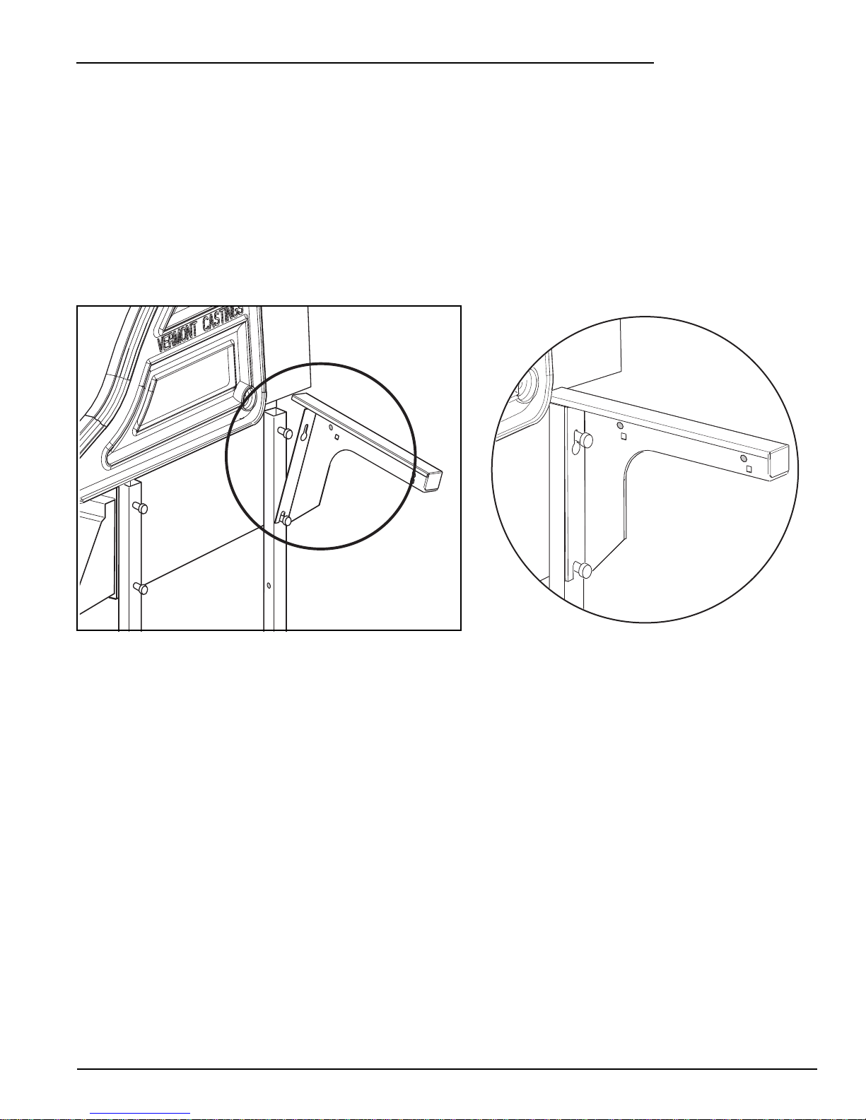
Step 5: Assemble Shelf Supports
Required: (2) Left Shelf Supports, (2) Right Shelf Supports.
Attach a right and left shelf support to the right side by loosening the 4 leg bolts (2 to 3 turns only) so that
the supports can be slid over the bolt heads. Push the supports down fully, ensuring undersides of supports
are resting on top of the legs, then tighten the bolts. Repeat for left side (Fig 5).
.
Fig. 5
Page 5
 Loading...