

Page 1
VC400 ASSEMBLY
VC400 ASSEMBLY PROCEDURES
Tools Required: Knife or Scissors, Hammer, 7/16” (11 mm) wrench/ratchet or an adjustable wrench,
Philips or Robertson screwdriver.
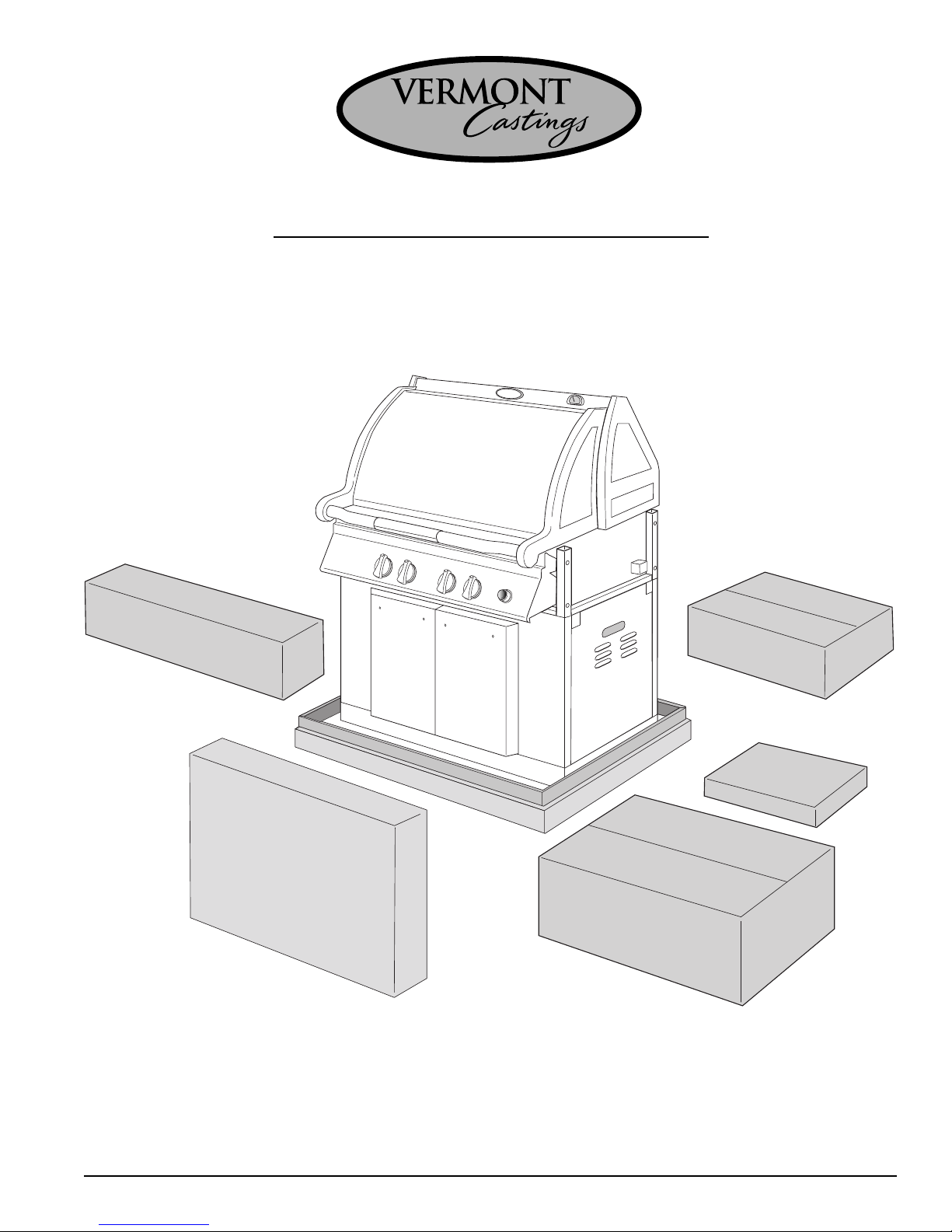
Step 1: Unpack carton
Box
#
4
Box
VERMONT
C
astings
VERMONT CASTINGS
VERMONT
Castings
Box
#
5
Box
#
3
#
1
Use the knife or scissors to cut the strapping on the package then lift off the cardboard cap. Remove the
cardboard sleeve lifting it straight over top of the barbecue. Check the 5 enclosed parts kits, against the
parts list (Appendix A) to ensure that no parts are missing.
Page 1
Box
#
2
Page 2
VC400 ASSEMBLY
VERMONT
Castings
VERMONT
C
astings
VERMONTVERMONT CASTINGS
Caster
Insert
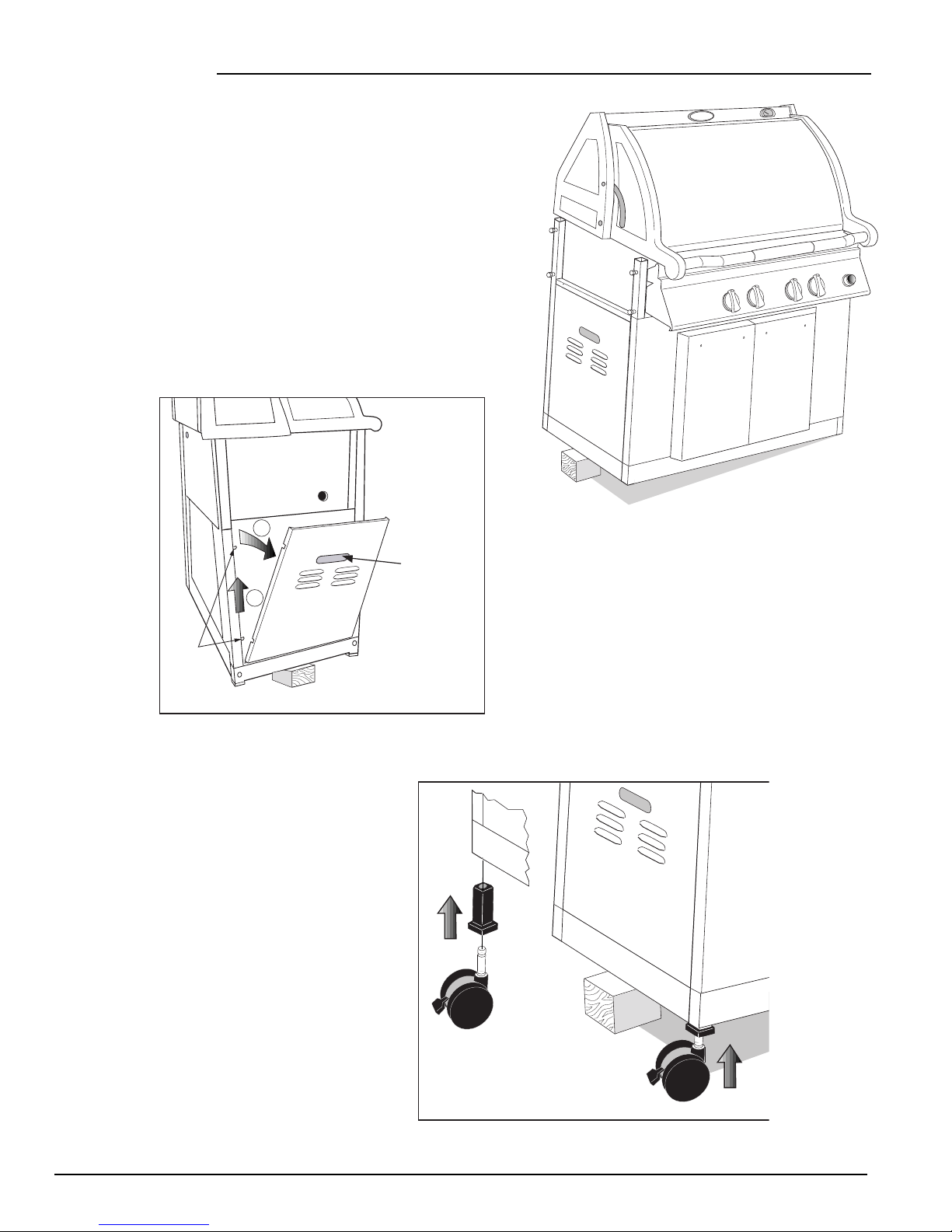
Step 2: Prop up left hand side of the barbecue
In order to attach casters and wheels to the barbecue,each side
of the unit must alternately be propped up to provide access to
the bottom of the legs. A block of wood or other solid item
about 4-6 inches high will suffice for this purpose.
The same process can be used with the right
legs for attachment of the unit’s wheels.
NOTE: BEFORE BEGINNING ANY ASSEMBLY, REMOVE THE
BARBECUE’S SIDE PANELS TO PREVENT THEM FROM BEING
DAMAGED.
2
1
Shoulder
Screws
Step 3: Install Casters
Materials Required:
Two casters and two caster inserts.
Place a caster insert in the bottom of the
rear left leg and tap it into place with a
hammer. Tap the other caster insert into
the front left leg. Snap the casters into
the inserts.
Hand Hold
(Lift Up and Pull Out)
Page 2
Page 3
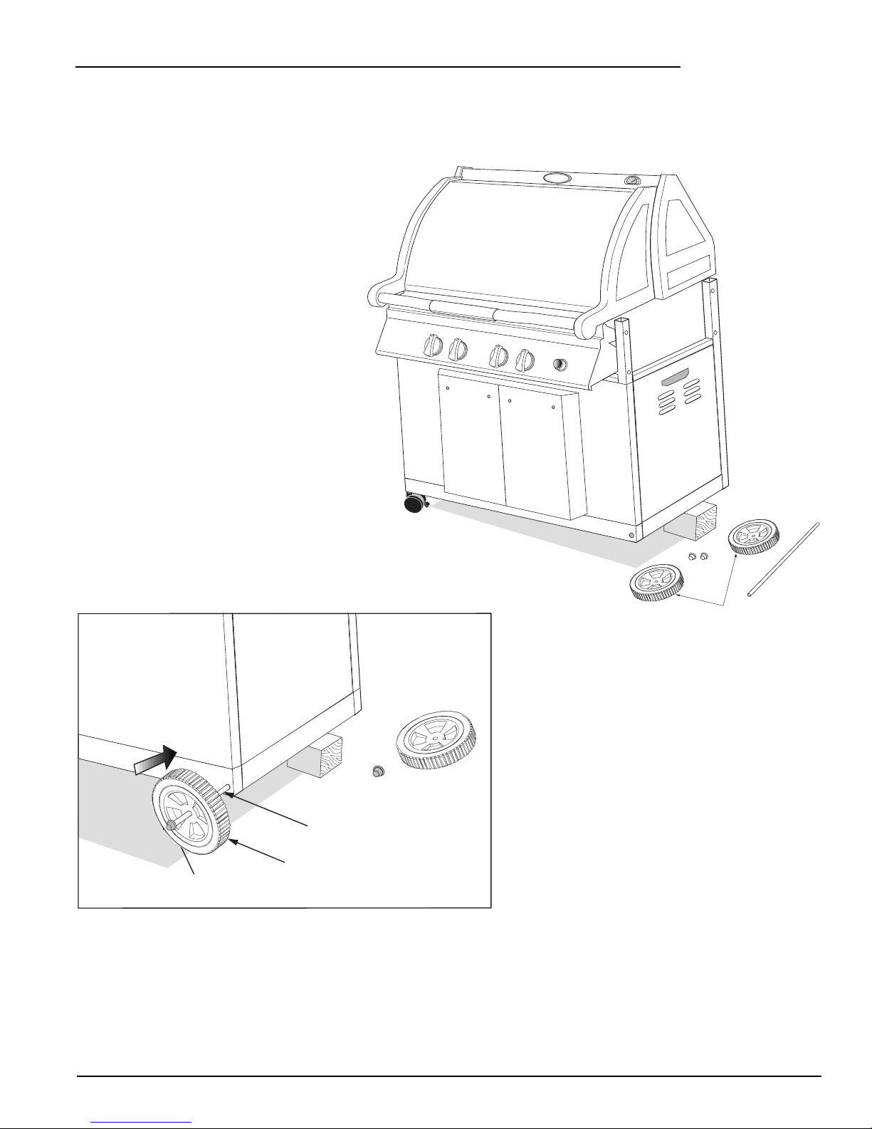
Step 4: Attach Wheels
Caps
Wheels
Axle
VERMONTVERMONT
C
astings
VERMONTVERMONT
C
astings
VERMONT CASTINGS
Materials Required: 1/2” diameter axle; two
1/2” axle caps and two wheels.
Prop up the right hand side of the barbecue
using the method described in Step 2.
Tap a cap onto one end of the axle. Push
a wheel onto the axle flush against the
cap with the cone shaped side of the
wheel facing inward. Insert the axle
through the holes at the bottom of the
right hand legs. Finally slide the other
wheel into place on the axle, again with
the cone shaped side facing inward, and
tap the other axle cap
onto the axle.
VC400 ASSEMBLY
Wheel
Cap
NOTE: PLACE THE UNIT ON LEVEL GROUND. LOCK CASTERS BEFORE
PROCEEDING TO STEP 5 AND BEGINNING FURTHER ASSEMBLY.
Axle
Page 3
Page 4
VC400 ASSEMBLY
Shim
Step 5: Attach Shelf Supports Materials Required: Left and Right shelf supports and eight
shim washers.
VERMONT CASTINGS
Attach the right shelf support to the barbecue by loosening the 4 existing leg bolts, approximately 3 turns, so
that the shelf support can slide over the bolt heads. Insert a shim washer sideways behind the head of one of
the bolts and in front of the shelf support. Tighten the bolt using the 7/16” (11 mm) wrench/ ratchet or
adjustable wrench. Repeat inserting shim washers behind the heads of the remaining 3 bolts.
Attach the left shelf support in the same manner.
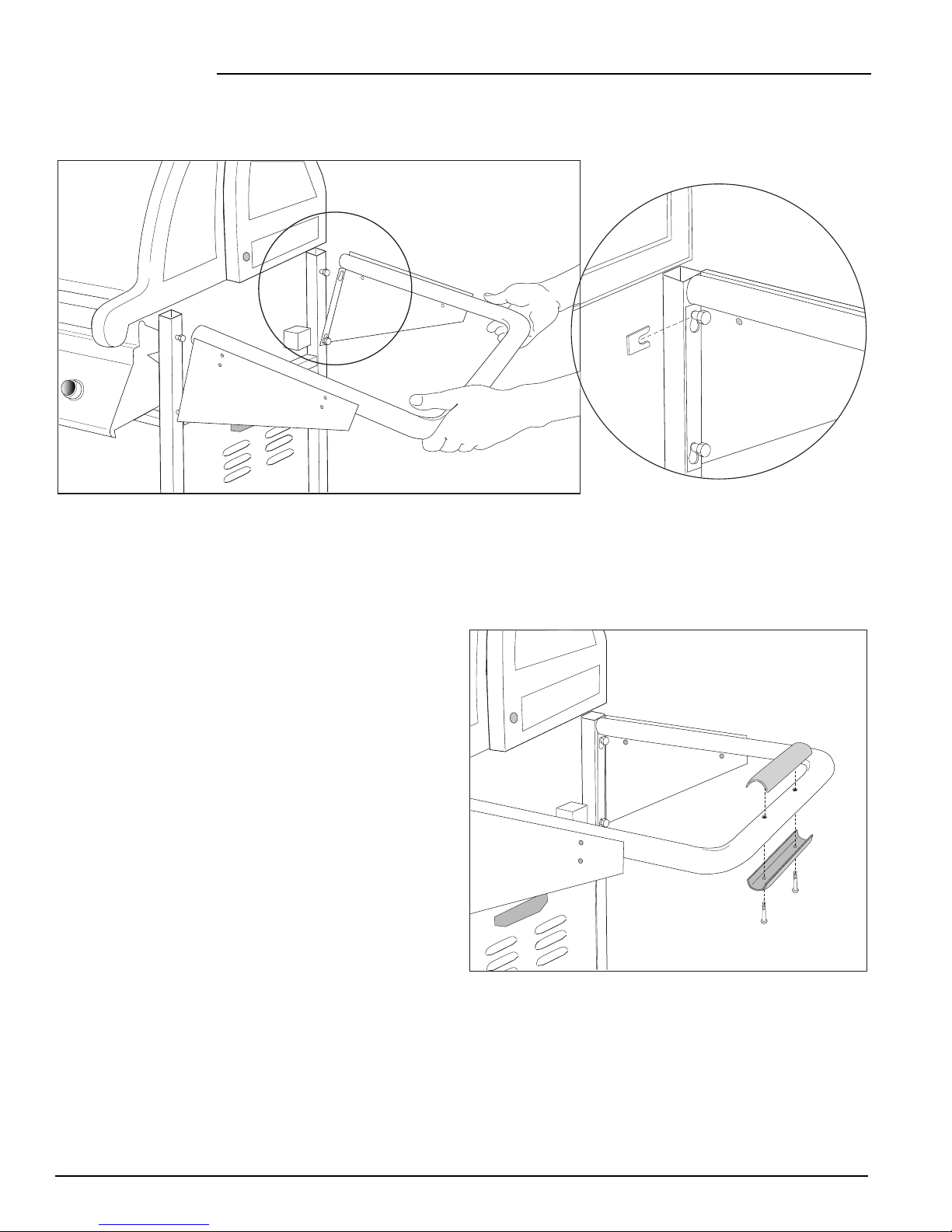
Step 6: Install Handle Grips
VERMONT CASTINGS
Materials Required: Three handle
grip sets (six pieces total) and six
Castings
#4 x 3/4” Philips screws.
VERMONT
Place the top half of one handle grip, the half bearing the Vermont Castings logo, onto the right shelf support
handle. Use the holes provided as a guide. Snap the two halves of the handle grip together and secure them
using two Philips screws and a Philips screwdriver.
Repeat this procedure for the left shelf support handle grip.
Finally, attach the last handle grip set to the front lid handle.
Page 4
Page 5

VC400 ASSEMBLY
Step 7: Attach Front Condiment Shelves
Materials Required: Four #10-24 x 1/2” carriage bolts; two # 10-24 x 1/4” nylon bolts; two # 10-24 nylon
nuts; four #10-24 lock nuts; four 1” diameter rubber washers; the right front shelf; the left front shelf.
1
Align the two holes of the right front
condiment bin with those provided on the front
bracket of the right shelf support. Use two carriage
bolts (bolts with a squire shoulder below the head)
in the front; two rubber washers between the
condiment shelf and support bracket; and two
lock nuts at the rear to secure shelf to the unit at
each hole. Assemble loosely.
2
Next secure the shelf to the front
control panel by aligning the center hole on the
inside bottom side of the shelf with the hole
provided on the right side flange of the control
panel. Loosely assemble the pieces together
using a nylon nut & bolt.
Roundhead
Bolt
2
VERMONT CASTINGS
1
Rubber
Washer
Carriage
Bolt
Lock
Nut
VERMONT
Castings
Repeat to attach the left condiment shelf.
Do not tighten he fasteners yet.
Step 8: Attach Side Shelves
Materials Required: Nine #10-24 x 1/2” round head bolts; nine #10-24 lock nuts; and the left and right side
shelves and the Tool Holder.
NOTE: See separate rotiserie instructions to
assemble rotisserie bracket to left side shelf.
1 Fit the left side shelf onto the left shelf
support and secure it to the unit at the rear
using two bolts and two lock nuts. Assemble
loosely. 2 Secure the left side shelf to the
left front shelf with one bolt and nut.
NOTE: The Tool Holder may be assembled
at this time to the left or right end. The top
of the Tool Holder fits under the edge of the
shelf. 3 Finally, secure the left side shelf to
the side of the base using a bolt and nut.
Tighten all connections on both the condiment bins and side shelf.
VERMONT
Castings
Bolt
Tool Holder
Bolt
1
Nut
Bolt
3
2
Nut
Repeat for the right side shelf.
Page 5
Page 6

VC400 ASSEMBLY
Step 9: Attach the Handles to the Cabinet Doors
Materials Required:
Two door handles with four screws.
Attach a door handle to the left cabinet door by aligning
the ends of the handle with the two holes provided on
the top right side of the door. Secure the handle using the
screws provided and a Philips screwdriver.
Repeat for the right hand door handle.
Step 10: Insert the Bottom Panels and Install Tank Tip-out
Materials Required: Two bottom panels. Two #8-18 self-tapping screws for Propane Model Only.
Insert the bottom panels of the cabinet by placing the lips of the panels on the front and rear leg brace. For Natural
Gas models two shallow panels are used. For Propane models one shallow panel is used on the left side.
Bottom
Panel
Bottom
Panel
Natural Gas Model
For Propane models the right hand cylinder base panel
has been loosely assembled at the factory. Push the base
pan down until the lips of the panel sit on the front and
rear leg braces. Tighten the four screws that secure the
base pan.
Attach the bracket of the tank tip-out assembly to the
right end brace with two self-tapping screws.
Bottom
Panel
Propane Model
Bottom Panel
For Propane
Models
Screws
Screws
Page 6
Page 7

Step 11: Set up the Grease Pan and Grease Cup Holder
Materials Required: Grease pan; grease
cup, grease cup holder assembly.
Beneath the cooking unit a guide track has been
provided so that the grease pan can easily slide
in and out. This guide track can be accessed
from the left side of the barbecue. Slide the
grease pan halfway out to install the grease cup
assembly. Insert a disposable aluminum pan into
the grease cup holder then hook it onto the slots
provided on the end of the grease pan. Push the
grease pan back into place.
(Note: the grease cup should be hanging below
the square hole provided in the grease pan).
VC400 ASSEMBLY
Grease Pan
Grease Cup
Holder
Grease Cup
Step 12: Attach the Back Panel of the Cabinet
Materials Required: Two #8-18 self-tapping screws; two #8-18 self-tapping shoulder screws; back panel.
Screws
Shoulder
Screws
Install the self-tapping shoulder screws into the lowest holes in the rear leg panels.
Place the back panel, with the louvres facing down and to the rear, on top of the rear leg brace. Ensure that
the slots at the lower side flanges of the panel fit over the shoulder screws just installed in the rear leg
panels. Secure the top of the panel using two self-tapping screws in the holes provided at the top right and
left hand corners of the panel.
Page 7
Page 8

VC400 ASSEMBLY
Step 13: Install Sear Plates, Cooking Grates, Warming Rack, and Smoker Boxes
Materials Required: Two sear plates; smoker box with lid; three cooking grates, and the warming rack.
Place the sear plates into the barbecue ensuring that
their edges are facing downward. The sear plate with
the large square cutout will house the smoker box. The
plate with the smoker box hole should be placed so that
it is closer to the rear of the unit on the left side of the
Grill. If the plates have arrows stamped on them,
position the plates so the arrows point to each other.
Place the lid on the smoker box.
Position the 3 cooking grates in the base unit with the
finger holes to the front. These may be turned over to
provide an angled flat surface for delicate foods.
Slip the rear lip of the warming rack into the two
supports extruding above the rotisserie burning housing.
Let it rest in a level position.
To use the rotisserie smoker box. Remove the warming
rack, and sit the box and lid on top of the rotisserie housing.
Smoker
Box
Cooking
Grates (3)
Sear
Plates (2)
VERMONT
Warming
Rack (1)
Castings
Finger
Hole
Step 14: Insert the Gas
Tank
Materials Required: Gas tank.
(Not supplied with barbecue)
Rotate the tank tip-out down until
its pivoting handle contacts the
ground. Place your propane tank
on the cradle of the tip-out. Rotate
the tip-out back to the upright
position.
Connect the tank to the main
regulator.
Page 8
Page 9

VC400 ASSEMBLY
Hand Hold
(Lift Up and Pull Out)
2
1
Shoulder
Screws
Step 15: Reinstall the Base Panels of the Cabinet
Materials Required: 2 side panels
Take the smaller base panel with the louvres facing down and out and attach it to the right side of the cabinet
by sliding the holes on the side of the panel onto the shoulder screws protruding from the legs. Push the
panel down to secure it in position.
Repeat for the left base panel.
APPENDIX A
The contents of the VC400 parts kits included in the appliance pack should be as follows:
Box 1:
Warming Rack (1)
Rear Lower Panel (1)
Left Stainless Steel Side Shelf (1)
Right Stainless Steel Side Shelf (1)
Axle (1)
Box 2:
Shelf Support Assembly (2)
Left Stainless Steel Condiment Shelf (1)
Right Stainless Steel Condiment Shelf (1)
Bottom Panel - Plain (1)
Sear Plate - Right Hand (1)
Sear Plate - Left Hand (1)
Smoker Box-Rotisserie-Body (1)
Smoker Box-Rotisserie-Lid (1)
Tool Holder (1)
Parts Bag
#50000030 Smoker Box (1)
#50000032 Smoker Box Lid (1)
#50000092 Wheels (2)
#50000090 Casters (2)
#50000091 Caster Inserts (2)
Grease Cup (2)
Grease Cup Holder (1)
Handle Grip Top (3)
Handle Grip Bottom (3)
Hardware Kit (1)
Door Handle and Mounting Screws (2)
Box 3:
Cooking Grates (3)
Box 4:
Rotisserie Motor (1)
Spit Rod (1)
Spit Fork Kit (1)
Rotisserie Support Bracket (1)
Rotisserie Motor Bracket (1)
Rotisserie Bracket Guide (1)
Box 5:
Side Burner Assembly (1)
Side Burner Cover (1)
Side Burner Bracket (1)
Hinge Rod (1)
Push Nut - 1/4” (2)
Page 9
Page 10

VC400 ASSEMBLY
VC400 ASSEMBLY DRAWING
23
10
25
40
26
16
14
55
27
20
13
24
57
36
56
22
21
6
51
54
44
19
8
12
48
41
7
50
43
49
53
52
4
15
39
31
29
2
47
5
30
32
18
17
9
1
3
42
28
45
46
35
33
37
Page 10
38
34
Page 11

VC400 PARTS LIST
VC400 ASSEMBLY
ITEM QTY PART N0. DESCRIPTION
1 1 50000425 Base Assy
2 2 50000212 Brace Leg Front/Rear
3 2 50000241 Brace Leg End
4 2 50000038 Burner Main Assy
5a 1 50000471 Valve/Manifold Assy NG
5b 1 50000470 Valve/Manifold Assy LP
6 1 50000356 Plate Heat Set
7 1 50000225 Panel Base Left
8 1 50000226 Shelf Side Right
9 1 50000433 Burner Oven Assy
10 1 50000746 Rotiss Housing / Screen Assy
11 -- -- -12 1 50000430 Deflector Oven
13 1 50000047 Burner Rotiss Assy
14 1 50000357 Box Assy Smoke Set
15 1 50000043 Flash Tube
16 1 VCCG1A Cook Grates Cast
17 1 50000229 Base Panel Right
18 1 50000230 Support Shelf Assy
19 1 50000439 Electrode Oven
20 1 50000261 Warming Rack
21a 1 50000455 Tube and Orifice Assy Rotiss LP
21b 1 50000456 Tube and Orifice Assy Rotiss NG
22a 1 50000453 Tube and Orifice Assy Oven LP
22b 1 50000454 Tube and Orifice Assy Oven NG
23 1 50000234 Shelf Side Left
24 1 50000414 Lid Assy Rear Black
25 1 50000007 Logo
26 1 50000419 Lid Assy Front
27 1 50000227 Panel Rear Lower
28 1 50000318 Support Tank Assy
29 1 50000360 Wheel (2)
30 1 50000310 Front Door Assy Right
31 1 50000312 Front Door Assy Left
32 1 50000095 Panel Bottom Plain
33 1 50000460 Console S/S
34 1 50000742 Shelf Assy Front Right
35 1 50000743 Shelf Assy Front Left
36 1 50000355 Pivot Bolt Set (2)
37 1 50000076 Knob Control
38 1 50000438 Igniter Kit
39 1 50000368 Handles Door Deluxe Set
40 1 50000642 Grip Handle Set (3)
41 1 50000365 Lid Bumpers (6)
42 1 50000093 Axle
43 1 50000361 Grease Cup Holder & Cups (2)
44 1 50000466 Electrode Rotiss
45 1 50000431 Electrode Main Short
46 1 50000523 Electrode Main Long
47 1 50000061 Hose Regulator
48a 1 50000062 Valve Side Burner LP
48b 1 50000197 Valve Side Burner NG
49 1 50000024 Heat Shield Console
50 1 50000027 Pan Grease
ITEM QTY PART N0. DESCRIPTION
51 1 50000541 Bracket Rotiss Motor
52 2 50000079 Leg Left
53 2 50000084 Leg Right
54 1 500000151 Bracket Guide Rotiss
55 1 50000286 Spit Rod Rotiss
56 1 50000399 Support Rotiss Spit Rod
57 1 50000006 Gauge Temp
- 1 50000359 Caster & Insert Set (2)
- 1 50000511 Hardware Pack
- 1 50000335 Valve/Regulator Assy LP
- 1 50000336 Valve/Hose Assy NG
- 1 50000443 Decal Control Panel
- 1 50000367 Ignitor 2 Term & Knob
- 2 50000113 Knob Valve S/B
- 1 50000114 Burner S/B
- 1 50000115 Electrode S/B
- 1 50000444 Manual Use/Care
- 1 50000461 Manual Assy 400B
- 1 50000384
- 1 50000385
- 1 50000630 Rotisserie Motor
- 1 50000120 Cover Side Burner
- 1 50000747 Rotisserie Smoker Kit
- 1 50000286 Rotisserie Spit (Rod)
- 1 50000287 Rotisserie Fork Kit
- 1 50000541 Rotisserie Motor Bracket
- 1 50000151 Rotisserie Bracket Guide
- 1 50000504 Tool Holder
Conversion Kit NG to LP (includes SB)
Conversion Kit LP to NG (includes SB)
Page 11
Page 12

VC400 ASSEMBLY
410 Admiral Blvd. • Mississauga, Ontario • Canada L5T 2N6 • 905-670-7777
The Vermont Castings
Majestic Products Company
www.cfmmajestic.com • www.vermontcastings.com
Page 12
50000461 04/01
 Loading...