

Page 1
VC100 ASSEMBLY PROCEDURES
Tools Required: Knife or Scissors, Hammer, 7/16” (11 mm) wrench/ratchet or an adjustable wrench,
Philips or Robertson screwdriver.
VERMONT
C
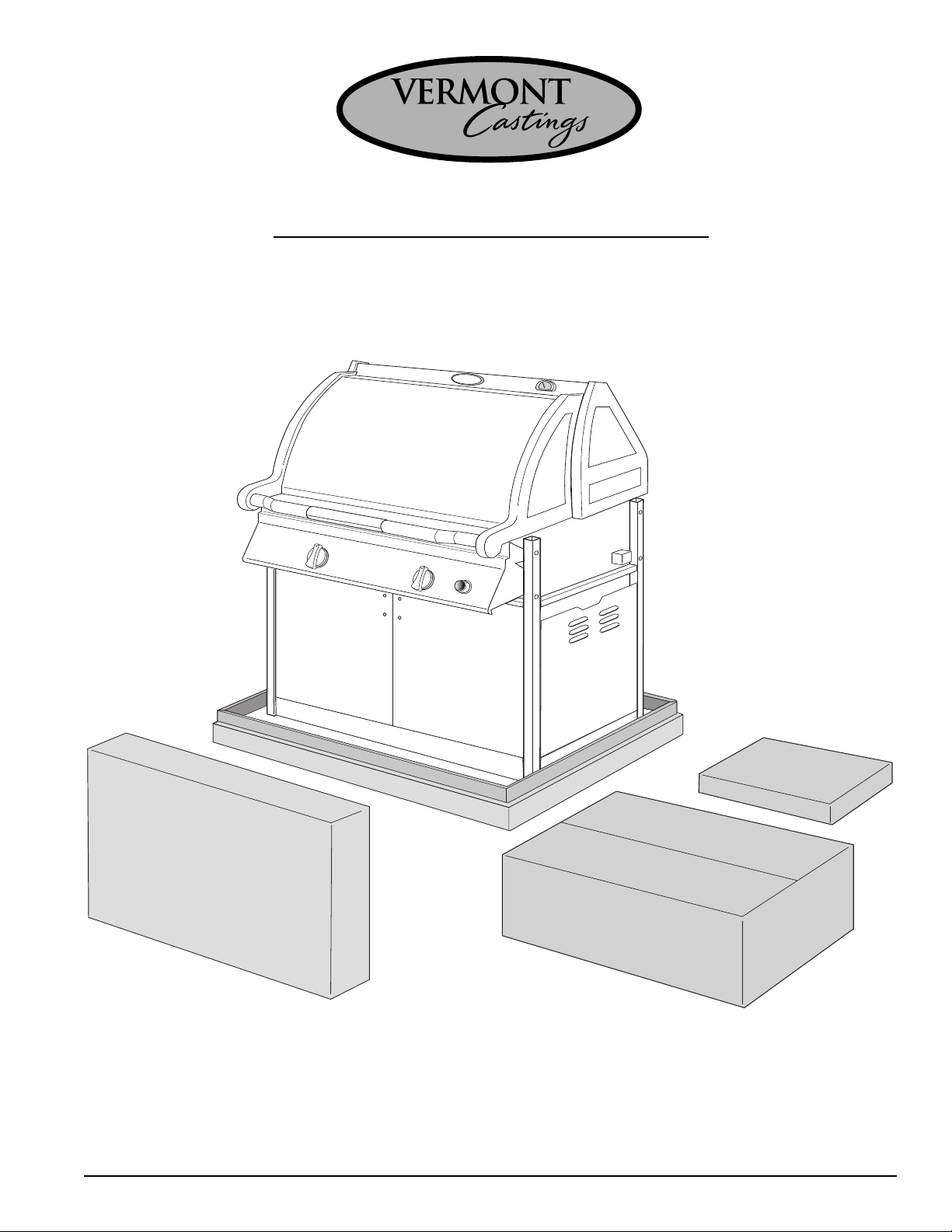
Step 1: Unpack carton
VERMONT
Castings
astings
VERMONT CASTINGS
Box
#
3
Box
#
1
Box
#
2
Use the knife or scissors to cut the strapping on the package then lift off the cardboard cap.
Remove the cardboard sleeve by lifting it straight over top of the barbecue. Check the 3 enclosed
parts kits, against the parts list (Appendix A) to ensure that no parts are missing.
Page 1
Page 2
VC100 ASSEMBLY
VERMONT
Castings
VERMONTVERMONT
C
astings
VERMONT CASTINGS
Caster
Insert
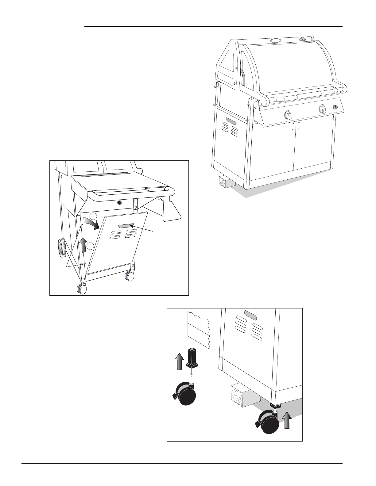
Step 2: Prop up left hand side of the barbecue
In order to attach casters and wheels to the barbecue, each side
of the unit must alternately be propped up to provide access to
the bottom of the legs. A block of wood or other solid item
about 4-6 inches high will suffice for this purpose.
The same process can be used with the right
legs for attachment of the unit’s wheels.
NOTE: BEFORE BEGINNING ANY ASSEMBLY, REMOVE THE
BARBECUE’S BASE PANELS (See Fig. 1) TO PERVENT THEM
FROM BEING DAMAGED.
2
1
Shoulder
Screws
Step 3: Install Casters
Materials Required:
Two casters and two caster inserts.
Place a caster insert in the bottom of the
rear left leg and tap it into place with a
hammer. Tap the other caster insert into
the front left leg. Snap the casters into
the inserts, and lock casters.
Hand Hold
(Lift Up and Pull Out)
Fig. 1
Page 2
Page 3
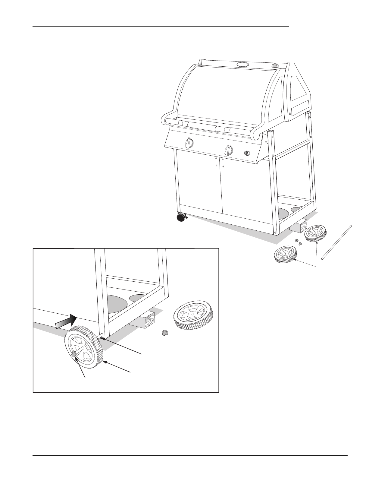
Step 4: Attach Wheels Materials Required: axle; two axle caps and two wheels.
VERMONTVERMONT
astings
C
Prop up the right hand side of the barbecue using
the method described in Step 2.
VC100 ASSEMBLY
Tap a cap onto one end of the axle. Push a
wheel onto the axle flush against the cap,
the cone shaped side of the wheel facing
inward. Insert the axle through the holes at
the bottom of the right hand legs. Finally
slide the other wheel into place on the axle,
again with the cone shaped side facing
inward, and tap the other axle cap
onto the axle.
VERMONT
C
VERMONT CASTINGS
astings
Caps
Axle
Wheels
Axle
Wheel
Cap
NOTE: PLACE THE UNIT ON LEVEL GROUND. LOCK THE CASTERS BEFORE
PROCEEDING TO STEP 5 AND BEGINNING FURTHER ASSEMBLY.
Page 3
Page 4
VC100 ASSEMBLY
Shim
VERMONT
Castings
VERMONT CASTINGS
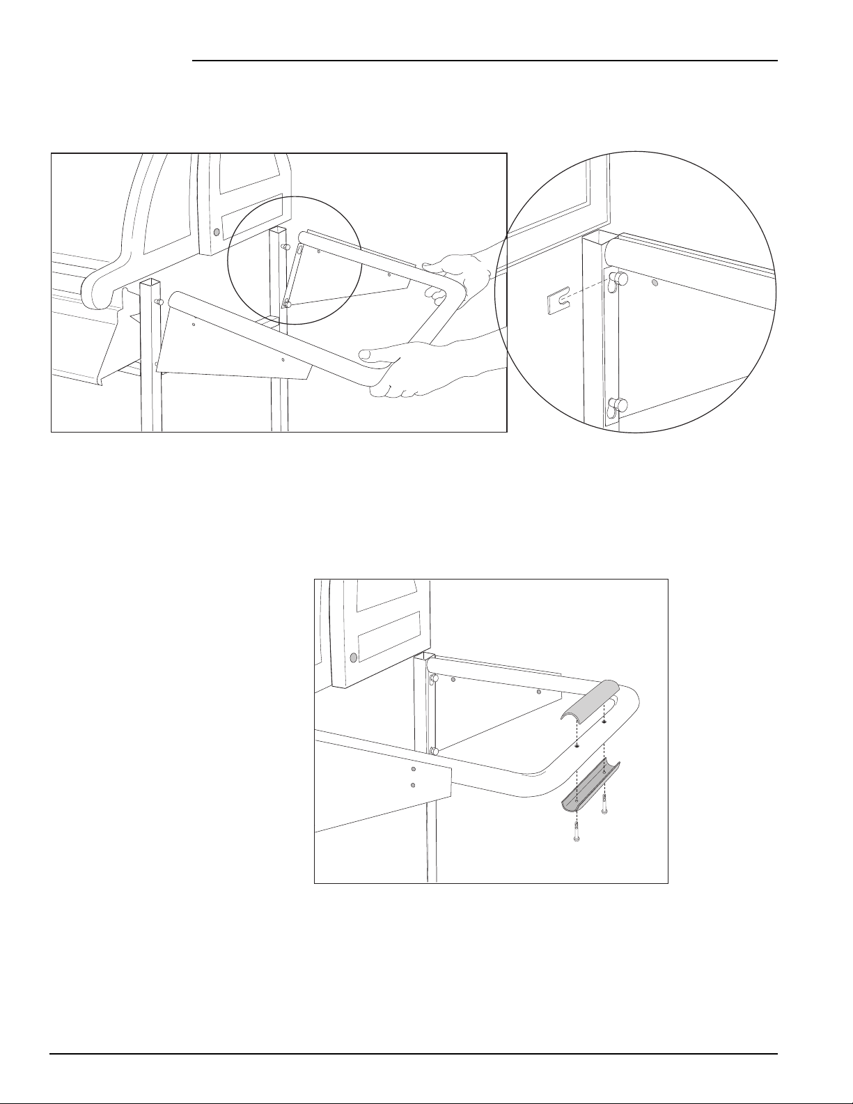
Step 5: Attach Shelf Supports Materials Required: Left and Right shelf supports and eight
shim washers.
VERMONT CASTINGS
Attach the right shelf support to the barbecue by loosening the 4 existing leg bolts, approximately 3 turns
only, so that the shelf support can slide over the bolt heads. Insert a shim washer sideways behind the head
of one of the bolts and in front of the shelf support. Tighten the bolt using the 7/16” (11 mm) wrench/
ratchet or adjustable wrench. Repeat inserting shim washers behind the heads of the remaining 3 bolts.
Attach the left shelf support in the same manner.
Step 6: Install Handle Grips
Materials Required: Three handle
grip sets (six pieces total) and six
#4 x 3/4” Philips screws.
Place the top half of one handle grip, the half bearing the Vermont Castings logo, onto the right shelf support
handle. Use the holes provided as a guide. Snap the two halves of the handle grip together and secure them
using two Philips screws and a Philips screwdriver.
Repeat this procedure for the left shelf support handle grip.
Finally, attach the last handle grip to the front lid handle.
Page 4
Page 5

VC100 ASSEMBLY
Step 7: Attach Front Condiment Shelves
Materials Required: Eight #10-24 x 1/2” bolts; four #10-24 x 1/4” nylon bolts; four # 10-24 nylon nuts;
eight #10-24 lock nuts; four 1” diameter rubber washers; 2 front shelves; the
right shelf end; the left shelf end.
7a -
Loosely attach the side of the right front shelf End Cap to a Front Shelf with
(2) 1/2” bolts & nuts. Attach the bottom flange of the End Cap to the Front Shelf
with a nylon nut & 1/4” bolt. Note: Flange should be below Front Shelf.
Tighten all fasteners.
7b - Align the two holes of the right front condiment
bin with those provided on the front bracket of the
right shelf support. Use a #10-24 x 1/2” bolt in the
VERMONT CASTINGS
front; a rubber washer between the shelf and support
bracket; and a #10-24 lock nut at the rear to secure
the right front condiment bin to the unit at each hole.
Assemble loosely. Next secure the condiment bin to
the front control panel by aligning the center hole on
the inside bottom side of the shelf with the hole
provided on the right side flange of the control panel.
Screw the pieces together using a nylon nut
& 1/4”
bolt.
1/4" Bolt
Repeat to attach the left condiment bin.
1/4" Bolts
Lock
Nut
Rubber
Washer
1/2" Bolt
Lock
Nuts
Nylon
Nut
1/2"
Bolts
Castings
VERMONT
Do not tighten he fasteners yet.
Nylon
Nut
Step 8: Attach Side Shelves
Materials Required: Nine #10-24 x 1/2” round head bolts; nine #10-24 lock nuts; and the left and right side
shelves, and the Tool Holder.
NOTE: See separate rotisserie instructions to assemble rotisserie bracket to left side shelf.
1 Secure the left side shelf to the side of
the base using a bolt and nut. Assembly
loosely.
2 Secure the left side shelf to the left
front shelf with one bolt and nut. NOTE: The
Tool Holder may be assembled at this time
to the left or right end. The top of the Tool
Holder fits under the edge of the shelf.
3 Finally, fit it the left side shelf onto the
left shelf support and secure it to the unit at
the rear using two bolts and two lock nuts.
Tighten all connections on the condiment
bin, side shelf, and Tool Holder.
Repeat for the right side shelf, place side
shelf plate into center of shelf.
VERMONT
Castings
Bolt
Tool Holder
Page 5
Bolt
3
Nut
VERMONT CASTINGS
2
Nut
Bolt
1
Page 6

VC100 ASSEMBLY
Step 9: Attach the Handles to the Cabinet Doors
Materials Required:
Two door handles with four screws.
Attach a door handle to the left
cabinet door by aligning the ends of the
handle with the two holes provided on
the top right side of the door. Secure the
handle using the screws provided and a
Philips screwdriver.
Repeat for the right hand door handle.
Step 10: Insert the Bottom Panels
Materials Required: Two bottom panels. Four #8-18 self-tapping screws for Propane Model Only.
Bottom
Bottom
Panel
Bottom
Panel
Natural Gas Model
Propane Model
Panel
Screws
Bottom Panel
For Propane
Models
Insert the bottom panels of the cabinet by placing the lips of the panels on the front and rear leg brace. For
Propane Models, the panel with the holes is to be placed on the right and secured with four self-tapping
screws.
Page 6
Page 7

Step 11: Set up the Grease Pan and Grease Cup Holder
Materials Required: Grease pan; grease
cup, grease cup holder assembly.
Beneath the cooking unit a guide track has been
provided so that the grease pan can easily slide
in and out. This guide track can be accessed
from the left side of the barbecue. Slide the
grease pan halfway out to install the grease cup
assembly. Insert a disposable aluminum pan into
the grease cup holder then hook it onto the slots
provided on the end of the grease pan. Push the
grease pan back into place.
(Note: the grease cup should be hanging below
the square hole provided in the grease pan).
VC100 ASSEMBLY
Grease
Pan
Grease
Cup Holder
Grease Cup
Step 13: Install Sear Plates, Cooking Grates, Warming Rack, and Smoker Boxes
Materials Required: Two sear plates; smoker box with
lid; three cooking grates, and the warming rack.
Place the sear plates into the barbecue ensuring that
their edges are facing downward. The sear plate with
the large square cutout will house the smoker box. The
plate with the smoker box hole should be placed so that
it is closer to the rear of the unit on the left side of the
Grill. If the plates have arrows stamped on them,
position the plates so the arrows point to each other.
Place the lid on the smoker box.
Position the 3 cooking grates in the base unit with the
finger holes to the front. These may be turned over to
provide an angled flat surface for delicate foods.
Slip the rear lip of the warming rack into the two
supports extruding above the rotisserie burning housing.
Let it rest in a level position.
To use the rotisserie smoker box. Remove the warming
rack, and sit the box and lid on top of the rotisserie housing.
Cooking
Grates (3)
Smoker
Box
Sear
Plates (2)
Castings
VERMONT
Warming
Rack (1)
Finger
Hole
Page 7
Page 8

VC100 ASSEMBLY
Step 14: Insert the Gas Tank
Materials Required: Cylinder. (Not supplied with barbecue)
NOTE: Refer to the Users Manual for the propane
cylinder specifications and for cylinderfilling
requirements, before lighting the Grill.
Insert the propane cylinder into the hole provided in
the bottom right bottom panel. Connect the cylinder to
the main regulator.
Step 15: Reinstall the Base Panels of the Cabinet
Materials Required: 2 base panels
Take the smaller base panel with the louvers facing down and out and attach it to the right side of the cabinet
by sliding the holes on the side of the panel onto the shoulder screws protruding from the legs. Push the
panel down to secure it in position.
Repeat for the left base panel.
1
Hand Hold
2
(Lift Up and Pull Out)
Shoulder
Screws
Page 8
Page 9

VC100 ASSEMBLY
Step 16: Install Ignitor Battery
Materials Required: ‘AA’ Battery
Unscew the ignitor button knob, remove the spring, and place the AA battery positive end down into the
holder. Replace the spring over the battery and tighten the cap. The ignitor should make an audible snap
every second when the button is pushed.
Follow the leak test procedure and operation guide in the user’s manual.
APPENDIX A
The contents of the VC200 parts kits included in the appliance pack should be as follows:
Box 1: #50000097 Left Side Shelf (1)
#50000099 Right Side Shelf (1)
#50000260 Side Shelf Plate (1)
Box 2: #50000261 Warming Rack
#50000150 Shelf Support Assembly (2)
#50000440 Front Shelf (2)
#50000441 Front Shelf End-R (1)
#50000096 Bottom Panel – Tank (1) *
#50000095 Bottom Panel – Plain (1) * or (2)**
#50000028 Sear Plate – Right Hand (1)
#50000029 Sear Plate – Left Hand (1)
#50000093 Axle
#50000442 Front Shelf End-L (1)
#50000504 Tool Holder
#50000489 Smoker Box-Rotisserie Body
#50000490 Smoker Box-Rotisserie Lid
* Propane Models Only
** Natural Gas Models Only
Parts Bag
(Box 2)
Box 3: #50000156 Cooking Grates (3)
#50000030 Smoker Box (1)
#50000032 Smoker Box Lid (1)
#50000092 Wheels (2)
#50000090 Casters (2)
#50000091 Caster Inserts (2)
#50000126 Aluminum Grease Cups (2)
#50000125 Grease Cup Holder (1)
#50000525 Handle Grip Top (3)
#50000524 Handle Grip Bottom (3)
#50000452 Hardware kit
#50000135
Door Handle and mounting screws (2)
Page 9
Page 10

VC100B ASSEMBL Y DRAWING
28
16
14
41
40
15
20
39
26
27
34
33
11
12
8
37
32
9
24
19
21
22
30
6
7
36
43
1
23
35
3
2
13
25
31
29
42
10
5
18
17
38
Page 10
4
Page 11

VC100B PARTS LIST
Item Qty Part # Description
1 1 50000425 Base Assy
2 2 50000236 Brace Leg End
3 1 50000237 Brace Leg Rear
4 2 50000440 Shelf Front
5 1 50000463 Console 100B
6 2 50000038 Burner Main Assy
7a 1 50000473 Valve Manifold Assy NG
7b 1 50000472 Valve Manifold Assy LP
8 1 50000356 Plate Heat Set
9 1 50000099 Shelf Side Right
10a 1 50000442 End Cap Shelf - Left
10b 1 50000441 End Cap Shelf - Right
11 1 50000431 Electrode Main Short
12 1 50000523 Electrode Main Long
13 1 50000093 Axle
14 1 50000357 Box Assy Smoke Set
15 1 50000043 Flash Tube
16 1 VCCG1A Cook Grates Cast (3)
17 1 50000465 Igniter Kit 100B
18 2 50000076 Knob Control
19 1 50000097 Shelf Side Left
20 1 50000027 Pan Grease
21 2 50000079 Leg Left
22 2 50000084 Leg Right
23 2 50000150 Support Shelf Assy
24 1 50000260 Plate Side Shelf
25 1 50000510 Brace Leg Front 100
26a 1 50000414 Lid Assy Rear Charcoal
26b 1 50000446 Lid Assy Rear Green
27 1 50000007 Log0
28a 1 50000419 Lid Assy Front Charcoal
28b 1 50000449 Lid Assy Front Green
29 1 (0)* 50000096 Panel Bottom LP
30 2 (2)* 50000095 Panel Bottom Plain
31 1 50000360 Wheel (2)
32 1 50000361 Grease Cup Holder & Cups (2)
33 1 50000642 Grip Handle Set (3)
34 1 50000006 Temp Gauge
35a 1 50000282 Panel Base Green
35b 1 50000129 Panel Base Charcoal
36a 1 50000128 Front Door –Left Charcoal
36b 1 50000366 Front Door – Left Green
37 6 50000365 Lid Bumpers (6)
38 1 50000248 Regulator/O.D. Assy
39 1 50000355 Pivot Pin & Bolt Set (2)
40 1 50000298 Plate Rotiss Cover
41 1 50000261 Warming Rack
42a 1 50000530 Door 100 Right Charcoal
42b 1 50000545 Door 100 Right Green
Item Qty Part # Description
43 1 50000024 Heat Shield Console
-- 1 50000303 Valve/Regulator Assy LP
-- 1 50000301 Valve/Hose Assy NG
-- 1 50000359 Caster & Insert Set
-- 1 50000452 Hardware Pack
-- 1 50000468 Decal
-- 1 50000444 Manual Use and Care
-- 1 50000467 Manual Assy 100
-- 1 50000380 Conversion Kit NG to LP
-- 1 50000381 Conversion Kit LP to NG
-- 1 50000386 Conversion Kit Side Burner NG to LP
-- 1 50000387 Conversion Kit Side Burner LP to NG
* Natural Models
Page 11
Page 12

The Vermont Castings, Majestic Products Company
410 Admiral Blvd. • Mississauga, Ontario, Canada L5T 2N6 • 905-670-7885
www.vermontcastings.com
50000467 12/00
 Loading...