

Vermont Castings Stardance 3070, Stardance SDV30, Stardance 3071, Stardance 3072, Stardance 3073 Homeowner's Installation And Operating Manual
INSTALLER / CONSUMER
SAFETY INFORMATION
PLEASE READ THIS MANUAL
BEFORE INSTALLING AND USING
APPLIANCE.
Stardance
WARNING!
IF THE INFORMATION IN THIS
MANUAL IS NOT FOLLOWED
EXACTLY, A FIRE OR EXPLOSION
MAY RESULT CAUSING PROPERTY DAMAGE, PERSONAL INJURY OR LOSS OF LIFE.
FOR YOUR SAFETY
Installation and service must be performed by a qualified installer, service
agency or the gas suppler.
WHA T T O DO IF YOU SMELL GAS:
• Do not try to light any appliance.
• Do not touch any electric switch; do
not use any phone in your building.
• Immediately call your gas supplier
from your neighbor’s phone. Follow
the gas supplier’s instructions.
• If you cannot reach your gas supplier,
call the fire department.
DO NOT STORE OR USE GASOLINE OR OTHER FLAMMABLE
VAPORS AND LIQUIDS IN THE
VICINITY OF THIS OR ANY OTHER
APPLIANCE.
Direct Vent/Natural
Vent Gas Heater
Model SDV30: 3070, 3071,
3072, 3073
Homeowner’s Installation
and Operating Manual
I
S
G
E
N
D
3456
This appliance may be installed in an after
market permanently located manufactured (mobile) home where not prohibited
by local codes.
This appliance is only for use with the
type of gas indicated on the rating plate.
This appliance is not convertible for use
with other gases unless a certified kit is
used.
INSTALLER: DO NOT DISCARD THIS MANUAL - LEAVE FOR HOMEOWNER
C
E
D
R
E
I
T
I
F
ANSI Z21.88b-2001 and CSA-2.33b-2001
Tested and listed to
CERTIFIED
Ver mont Castings, Majestic Products
410 Admiral Blvd. • Mississauga, Ontario, Canada L5T 2N6 • 905-670-7777
www.majesticproducts.com • www.vermontcastings.com
20003456 11/02 Rev. 7

Vermont Castings Stardance Direct Vent/Natural Vent Gas Heater
PLEASE READ THE INSTALLATION & OPERATING INSTRUCTIONS BEFORE USING APPLIANCE.
Thank you and congratulations on your purchase of a Vermont Castings stove.
IMPORTANT: Read all instructions and warnings carefully before starting installation. Failure to follow these
instructions may result in a possible fire hazard and will void the warranty.
Installation & Operating Instructions ........................................................................................................... 3
Stove Dimensions ............................................................................................................................. 4
Installation Requirements.................................................................................................................. 5
Locating the Stove ............................................................................................................................ 5
Clearance Requirements .................................................................................................................. 5
Parallel & Corner Installation............................................................................................................. 6
Wall and Ceiling Clearances ............................................................................................................. 6
Hearth Requirements ........................................................................................................................ 6
Gas Specifications ............................................................................................................................ 7
Gas Inlet and Manifold Pressures ..................................................................................................... 7
High Elevations ................................................................................................................................. 7
Horizontal & Termination - Direct Vent ONLY ................................................................................... 7
Vertical Termination - Direct Vent ONLY .......................................................................................... 8
Vent Termination Clearances............................................................................................................ 9
General Venting Information - Termination Location ...................................................................... 10
Termination Clearances .................................................................................................................. 11
Venting Requirements - Natural Vent ONLY................................................................................... 11
Venting Requirements and Options - Direct Vent ONLY ................................................................ 12
Assembly Procedures
Tools Required / Parts Bag Contents.............................................................................................. 13
Unpack the SDV30 Firebox and Stove Shell .................................................................................. 13
Remove the Log Set ....................................................................................................................... 13
Shell Assembly................................................................................................................................ 14
Install the Optional Fan ................................................................................................................... 15
Venting System Assembly - Direct Vent ......................................................................................... 16
Install Vent Adapter Pipe (CFM Vent Components)........................................................................ 16
Install Vent Adapter Pipe (Simpson Dura-Vent Components) ........................................................ 17
Side Wall Termination Assembly .................................................................................................... 17
Vent Termination Below Grade ....................................................................................................... 19
Vertical (Through the Roof) Vent Assembly .................................................................................... 20
Venting System Assembly - Natural Vent ....................................................................................... 21
Install the Vent Pipe ........................................................................................................................ 21
Install the Log Set ........................................................................................................................... 22
Connect Gas Supply Line ............................................................................................................... 22
Burner Information .......................................................................................................................... 23
Air Shutter Adjustment & Instructions ............................................................................................. 23
Complete the Assembly .................................................................................................................. 24
Install ON/OFF Switch..................................................................................................................... 25
Thermostat Connection (Optional) .................................................................................................. 25
Install the Front and Top Plates ...................................................................................................... 25
Operation
Your First Fire.................................................................................................................................. 26
Pilot and Burner Information ........................................................................................................... 26
Flame & Temperature Adjustment / Flame Characteristics............................................................. 26
Lighting and Operating Instructions ................................................................................................ 27
Troubleshooting - Honeywell #8420 Gas Control System .............................................................. 28
Instructions for RF Comfort Control Valve ...................................................................................... 29
Fuel Conversion Instructions........................................................................................................... 33
Maintenance
Annual System Inspection............................................................................................................... 36
Logset and Burner/Cleaning and Inspection ................................................................................... 36
Care of Cast Iron ............................................................................................................................. 36
Cleaning the Glass .......................................................................................................................... 36
Glass Replacement ......................................................................................................................... 36
Gasket Replacement....................................................................................................................... 37
Inspect the Vent System Annually .................................................................................................. 37
Check the Gas Flame Regularly ..................................................................................................... 37
Stove Disassembly.......................................................................................................................... 37
Wiring Diagram................................................................................................................................ 38
Replacement Parts ....................................................................................................................................... 39
Optional Accessories................................................................................................................................... 42
2
2
Warranty ........................................................................................................................................................ 43
Table of Contents
20003456

Vermont Castings Stardance Direct Vent/Natural Vent Gas Heaterr
General Information
The Stardance Direct Vent/Natural Vent Room Heater,
Model Nos. 3070, 3071, 3072 and 3073, is a vented gas
appliance listed to the ANSI standard Z21.88b-2001 and
CSA-2.33b-2001 for Vented Room Heaters, and CSA 2.17M91, Gas-Fired Appliances For Use at High Altitudes.
The installation of the Stardance Direct Vent/Natural
Vent Room Heater must conform with local codes, or in
the absence of local codes, with National Fuel Gas Code,
ANSI Z223.1 — latest edition and CSA B-149.1 Installation Code. (EXCEPTION: Do not derate this appliance for
altitude. Maintain the manifold pressure at 3.5” w.c. for
Natural Gas and 10.0” w.c. for LP gas at maximum input.)
Refer to Page 34 (RF only).
This appliance is only for use with the type of gas indicated on the rating plate. This appliance is not convertible
for use with other gases unless a certified kit is used.
Installation and replacement of gas piping, gas
utilization equipment or accessories, and repair and
servicing of equipment shall be performed only by a
qualified agency. The term “qualified agency” means
any individual, firm, corporation, or company that either
in person or through a representative is engaged in
and is responsible for (a) installation or replacement of
gas piping, or (b), the connection, installation, repair,
or servicing of equipment, who is experienced in such
work, familiar with all precautions required, and has
complied with all the requirements of the authority
having jurisdiction.
The Stardance Direct Vent/Natural Vent Room Heater
should be inspected before use and at least annually
by a qualified service agency. It is imperative that
control compartments, burners, and circulating air
passageways of the appliance be kept clean.
The Stardance Direct Vent/Natural Vent Room Heater
and its individual shut-off valve must be disconnected from
the gas supply piping during any pressure testing of that
system at test pressures in excess of 1/2 psig (3.5 kPa).
The Stardance Direct Vent/Natural Vent Room Heater
must be isolated from the gas supply piping system by
closing its individual manual shutoff valve during any pressure testing of the gas supply piping system at test pressures equal to or less than 1/2 psig.
'Direct Vent' describes a sealed combustion system in
which incoming outside air for combustion and outgoing
exhaust enter and exit through two separate concentric
passages within the same sealed vent system. The system does not use room air to support combustion. The
Direct Vent system permits the gas appliance to be vented
directly to the outside atmosphere through the side of the
house or vertically through the roof. Conventional venting
systems (Natural Vent) take air from the room for combustion and vent the exhaust vertically through the roof to the
atmosphere.
This appliance is approved for bedroom installations in
the U.S. and Canada.
This appliance may be installed in an aftermarket*
manufactured (mobile) home, where not prohibited by state
or local codes.
WARNING: Operation of this heater when not connected to a properly installed and maintained venting
system can result in carbon monoxide (CO) poisoning and possible death.
The Stardance Direct Vent/Natural Vent Room Heater,
when installed, must be electrically grounded in accordance
with local codes or, in the absence of local codes, with the
National Electrical Code ANSI/NFPA 70, (latest edition),
or of the current Canadian Electrical Code C22.1.
Due to high temperatures this appliance should be
located out of traffic and away from furniture and
draperies.
WARNING: This appliance is hot while in operation.
Keep children, clothing, and furniture away. Contact
may cause burns or ignition of combustible materials.
Children and adults should be alerted to the hazards
of high surface temperatures and should stay away to
avoid burns or clothing ignition. Young children should
be carefully supervised when they are in the same
room as the appliance.
Clothing or other flammable materials should not be
placed on or near the appliance.
Any safety screen, glass or guard removed for
servicing an appliance must be replaced prior to
operating the appliance.
The appliance area must be kept clear and free from
combustible materials, gasoline, and other flammable
vapors and liquids.
The flow of combustion and ventilation air must not
be obstructed. The installation must include adequate
accessibility and clearance for servicing and proper
operation.
WARNING: Do not operate the Room Heater with the
glass panel removed, cracked or broken. Replacement
of the panel should be done by a licensed or qualified
service person.
Do not use this appliance if any part has been under
water. Immediately call a qualified service technician
to inspect the appliance and to replace any part of the
control system and any gas control which has been
under water.
Do not burn wood, trash or any other material for
which this appliance was not designed. This appliance
is designed to burn either natural gas or propane only.
This gas appliance must not be connected to a
chimney flue serving a separate solid-fuel burning
appliance.
CAUTION: Label all wires prior to disconnection
when servicing controls. Wiring errors can cause
improper and dangerous operation.
Verify proper operation after servicing.
Proposition 65 Warning: Fuels used in gas,
woodburning or oil fired appliances, and the products of
combustion of such fuels, contain chemicals known to the
State of California to cause cancer, birth defects and other
reproductive harm.
California Health & Safety Code Sec. 25249.6
* Aftermarket: Completion of sale, nor for purpose of resale,
from the manufacturer.
20003456
3
Vermont Castings Stardance Direct Vent/Natural Vent Gas Heater
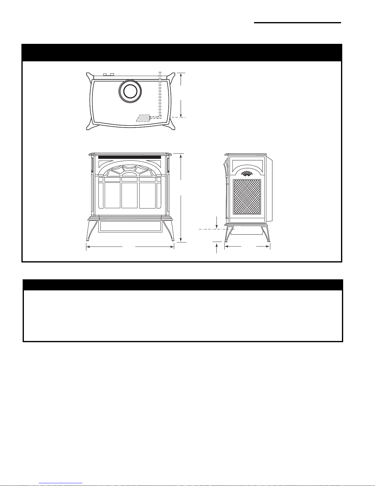
Stardance Direct Vent / Natural Vent Dimensions
9"
(229mm)
C
Valve
L
Inlet
26³⁄₄"
(680mm)
See Page 6 for Flue Collar
Centerline Dimensions.
Valve Inlet
C
L
3"
(76mm)
25"
(635mm)
Fig. 1 Stardance dimensions.
14¹⁄₂"
(355mm)
Attention
The Stardance stove is shipped from the factory as a Direct Vent Gas Heater. This heater may be converted
into a Natural Vent unit in the field. If a Natural Vent heater is desired, the Vermont Castings Z31D00
FSDHAG Draft Hood must be directly installed to the top of the unit according to the installation
instructions. The Draft Hood Adapter is available in the 7FSDHASK stove kit or as a separate item.
When the Stardance stove is converted to Natural Vent, it uses 4” vent pipe. For aesthetic purposes the
CFM direct vent system may be used up to the ceiling.
3456
4
4
20003456
Vermont Castings Stardance Direct Vent/Natural Vent Gas Heaterr
A
B
E
C
D
Installation Requirements
The installation must conform with local codes or, in
the absence of local codes, with the National Fuel Gas
Code, ANSI Z223.1 - latest edition. (EXCEPTION: Do
not derate this appliance for altitude. Maintain the
manifold pressure at 3.5 inches w.c. for Natural Gas,
and 10 inches w.c. for Propane).
In Canada, installation must be in accordance with the
current CSA B-149.1 Installation Codes and/or local
codes.
The installation should be done by a qualified
service person who is familiar with the building
codes and installation techniques appropriate for
your area to accomplish a safe and effective
installation.
Your dealer or your local gas supplier will be able
to refer a qualified service person.
WARNING: Due to high temperatures, the HEATER
should be located out of traffic and away from furniture
and draperies.
The surface of the Heater Is hot when it is in use.
Young children should be watched carefully when
they are in the same room when the Heater is in
use, and they should be taught to avoid the hot
surface. Keep any objects that can burn well away
from the Heater, and observe the recommended
clearances that follow.
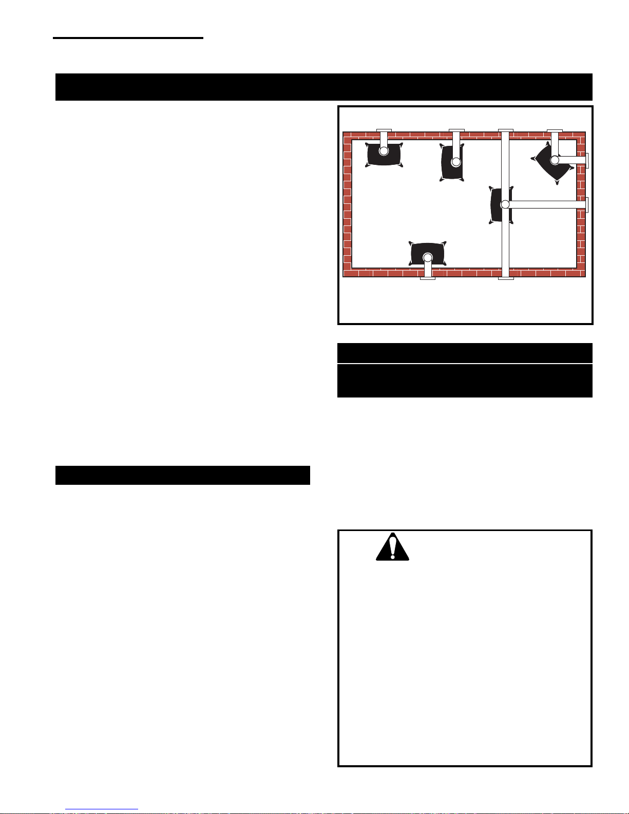
Locating the Stove
In choosing a location for the stove, consider:
• The location of outside walls;
• Where additional heat is needed:
• Where family members gather most often;
• The vent system requirements.
NOTE: We do not recommend the use of wallpaper
next to this stove. Over time, radiant heat may cause
the wallpaper to shrink, or may adversely affect the
binders in the wallpaper adhesive.
Direct Vent System Only
A. Flat on corner wall
B. Room Divider
C. Island
Fig. 2 Possible stove locations.
D. Cross Corner
E. Flat on wall
ST207a
Clearance Requirements
Minimum Clearances to Combustible
Materials
Measure side clearances as shown in Figures 5 and 6
from the outer edge of the cast iron stove top. Measure
rear clearances from the outermost surface of the steel
rear skirt.
The Stardance heater is approved for installation into
an alcove constructed of combustible materials to the
dimensions and clearances shown on the next page.
The same clearances apply in a standard parallel
installation.
WARNING:
• Always maintain required
clearances (air spaces) to nearby combustibles
to prevent fire hazard. Do not fill air spaces
with insulation. All venting components must
maintain a 1" (25mm) clearance to
combustible materials. Maintain a 6” (150mm)
clearance when using a single wall pipe.
• The gas appliance and vent system must be
vented directly to the outside of the building
and never be attached to a chimney serving a
separate solid fuel or gas-burning appliance.
Each direct vent appliance must use its own
separate vent system. Common vents are
prohibited.
• Refer to the manufacturer's instructions
included with the venting system for complete
installation procedures.
20003456
5
Vermont Castings Stardance Direct Vent/Natural Vent Gas Heater
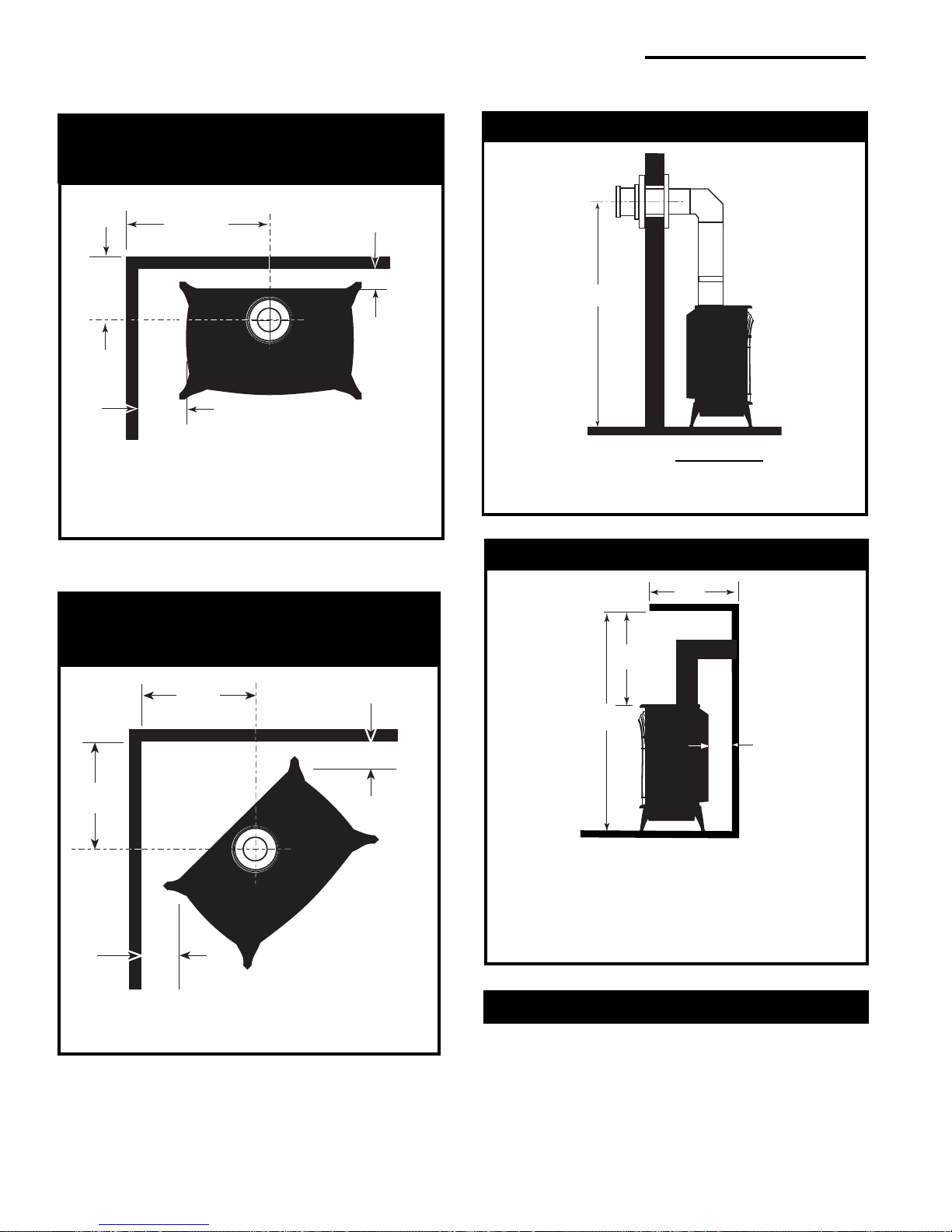
Parallel Installation: Minimum Clearance
and Flue Centerline, Direct Vent and
Natural Vent
C
L
C
D
C
L
B
Stove Clearances A: 4” (102mm)
B: 4” (102mm)
Pipe Centerlines C: 15¹⁄₂” (395mm)
D: 9” (229mm)
Fig. 5 Parallel installation, minimum back and side clearances, and flue centerlines.
A
ST128b
Corner Installation:
Minimum Clearance and Flue Centerline,
Direct Vent & Natural Vent
Wall Centerline from Floor
Direct Vent Only
A
A
Effective Minimum
Wall Thimble 56” (1480mm)(CFM Pipe)
Centerline 52” (1378mm) (Simpson DuraVent Pipe)
Fig. 4 Minimum wall thimble centerline.
Wall and Ceiling Clearances
Direct Vent Only
B
D
ST131b
B
A
B
A
Stove Clearance A: 4” (102mm)
Pipe Centerline B: 14¹⁄₂” (370mm)
Fig. 6 Corner installation, minimum corner clearances and
flue centerline.
ST129b
C
A
ST101b
A: Rear Wall 4” (102mm)
B: Min. Clearance 45¹⁄₄” (1154mm)*
C: Min. Alcove Height 72” (1830mm)*
D: Max. Alcove Depth 48” (1220mm)
Sidewall Clearance 4” (102mm)
*
needed for installing DuraVent Minimum Vent Kit #2792
or CFM/Majestic Minimum Vent Kit #7TFSDVSK.
Fig. 3 Dimensions and clearances to ceiling or alcove.
Hearth Requirements
The Stardance Heater must be installed on rigid
flooring. When the heater is installed directly on any
combustible surface other than wood flooring, a metal
or wood panel extending the full width and depth of the
unit must be used as the hearth. There are no other
hearth requirements.
6
6
20003456
Vermont Castings Stardance Direct Vent/Natural Vent Gas Heaterr
20
19
18
16
15
14
13
12
11
10
9
8
7
6
5
4
3
2
1
0
12 34567891011 12 13 14 15 16 17 18 19 20
Vertical Run (in feet)
(Measured from the appliance flue collar to the top of the vent pipe.)
Horizontal Run (in feet)
21
22
23
24
25
26
27
28
29
30
31
32
33
34
35
36
37
38
39
40
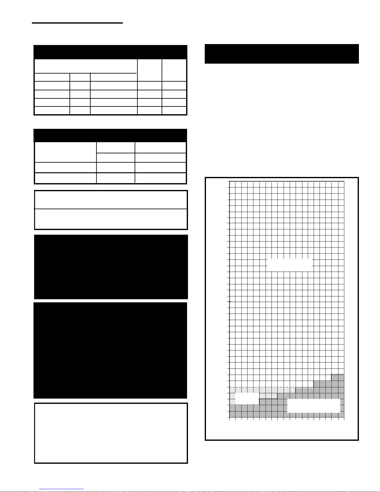
Gas Specifications
Max. Min.
Input Input
Model Fuel Gas Control BTU/h BTU/h
SDV30RN Nat Millivolt 28,000 20,000
SDV30RP Prop Millivolt 28,000 19,000
SDV30RFN Nat Comfort Control 28,000 20,000
SDV30RFP Prop Comfort Control 28,000 19,500
Weight: Fully assembled; 202 lbs.
Gas Inlet and Manifold Pressures
Natural LP (Propane)
Inlet Minimum 5.5” w.c. 11.0” w.c.
Inlet Maximum 14.0” w.c. 14.0” w.c.
Manifold Pressure 3.5” w.c. 10” w.c.
Stardance Direct Vent/Natural Vent
Certified to:
ANSI Z21.88b-2001 / CSA 2.33b-2001
Vented Gas Fireplace Heaters
Horizontal Termination -
Direct Vent ONLY
The vent must rise vertically a minimum of 24”
(610mm) off the top of the unit, before the first elbow.
The horizontal run may extend up to 20’ (6m) and
include a vertical rise of up to 40’ (12m). (Fig. 7)
Horizontal termination must also meet the criteria shown
in Figures 9 through 11.
• Approved vent systems must terminate above and
including the heavy line in Figure 7.
•Two 45˚ elbows may be substituted for each single
90˚ elbow.
•With a rise between 2' - 5', one 90˚ or two 45˚
elbows may be used.
The installation of your Vermont Castings stove must
conform with local codes, or in the absence of local
codes, with the National Fuel Gas Code ANSI
Z223.1 - latest edition, or CSA B149.1 Installation
code. (EXCEPTION: Do not derate this appliance for
altitude up to 4,500 feet (1,370m). Maintain the
manifold pressure at 3.5” w.c. for Natural Gas and
10.0” w.c. for LP Gas.
High Elevations
Input ratings are shown in BTU per hour and are
certified without deration for elevations up to
4,500 feet (1,370m) above sea level.
For elevations above 4,500 feet (1,370m) in USA,
installations must be in accordance with the
current ANSI Z223.1 and/or local codes having
jurisdiction.
In Canada, please consult provincial and/or local
authorities having jurisdiction for installations at
elevations above 4,500 feet (1,370m).
WARNING: Improper installation, adjustment, alteration, service or maintenance can
cause injury or property damage. Refer to
this manual for correct installation and
operational procedures. For assistance or
additional information consult a qualified
installer, service agency, or the gas supplier.
20003456
May use up to
three 90° Elbows
One 90°
Elbow
Unacceptable
Venting Configuration
Fig. 7 Horizontal vent termination window.
ST134a
7
Vermont Castings Stardance Direct Vent/Natural Vent Gas Heater
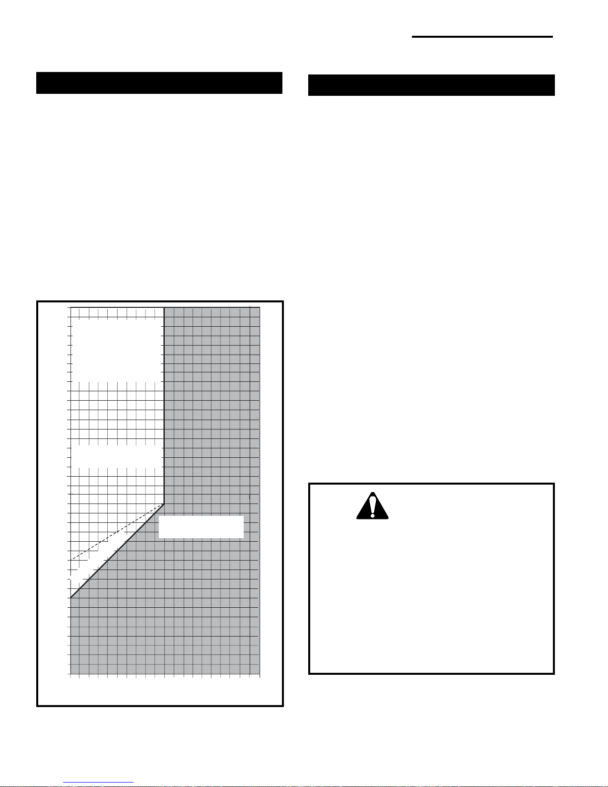
Vertical Termination - Direct Vent ONLY
A vertical vent system must terminate no less than 8'
(2.44m) and no more than 40’ (12m) above the appliance flue collar. A 2¹⁄₄" restrictor plate (supplied) must
be used where specified in all vertically terminated vent
systems. (Fig. 8) NOTE: The restrictor plate sup-
plied with the vertical termination should be discarded. Install restrictor plate supplied with stove
directly at stove outlet. A vertically terminated vent
system must also conform to the following criteria:
• No more than three 90˚ elbows may be used.
•Two 45˚ elbows may be substituted for one 90˚ elbow.
No more than six elbows may be used.
•Vent must rise a minimum of 2 feet before offset is
used.
•Termination height must conform to roof clearance as
specified in Figure 9.
40
39
38
All Vertical Termi-
37
nations in this area
36
Require use of the
35
2¹⁄₄” Restrictor
34
33
Plate*
32
31
30
29
28
27
26
25
Vertical terminations
24
must be within this area
23
22
21
Vertical Run (in feet)
20
19
18
16
(Measure from the appliance flue collar to the top of the vent pipe.)
15
14
13
12
11
10
No Restrictor Plate
9
8
7
6
5
4
3
2
1
0
1 2345678910111213141516171819
Horizontal Run (in feet)
Fig. 8 Vertical vent termination window.
*The Restrictor Plate is used on Direct Vent
Installations only.
Unacceptable
Venting Configuration
20
ST132a
Vent Termination Clearances
When planning the installation, consider the location of
the vent terminal and clearances. Some of the most
common clearances to keep in mind are shown in Figure
10.
Important: All vent clearances must be maintained.
Check your vent termination clearances against
Figures 9 through 11.
The vent should be placed so that people cannot be
burned by accidentally touching the vent surfaces
when the stove is operating.
The vent termination should be located where it cannot
be damaged by such things as automobile doors, lawn
mowers or snowblowers and it should be located away
from areas where it could become blocked by snow,
etc.
Some considerations are:
• Obstructions or impediments to venting.
• Nearby combustible materials that could come into
contact with combustion exhaust gases.
• Other nearby openings {within 12" (305mm)} through
which exhaust gas could reenter the building.
• All vegetation within 3' ((76mm) that may interfere
with the draft.
Other factors that influence where the installation will
be sited include the location of outside walls, where
additional heat may be desired in the home, where the
family members gather most regularly, and perhaps
most importantly, the distance limitations of the venting
system.
IMPORTANT
Direct Vent Only
• The horizontal termination must not be recessed
into the exterior wall or siding.
• Horizontal vent runs must be level toward the
vent termination.
• Clearances around the vent termination must be
maintained.
• For installations using Simpson DuraVent pipe,
parallel installations with minimum wall clearance
have restricted access for connecting the Horizontal Vent Cap straps to the vent pipe. See the
maker’s instructions for recommended installation procedures.
8
8
20003456

Vermont Castings Stardance Direct Vent/Natural Vent Gas Heaterr
Vent Termination Clearances
Your stove is approved to be vented either through the
side wall, or vertical through the roof.
• Vermont Castings, Majestic Products does not
require any opening for inspection of vent pipe.
• Only Vermont Castings, Majestic Products and
Simpson DuraVent venting components specifically approved and labelled for this stove may be
used.
• Minimum clearances between vent pipes and
combustible materials is one (1") inch (25 mm),
except where stated otherwise.
• Venting terminals shall not be recessed into a wall or
siding.
• Horizontal venting must be installed on a level plane
without an inclining or declining slope.
There must not be
garden sheds, fences, decks or utility buildings within
24" from the front of the termination hood.
Do not locate termination hood where excessive snow
or ice build up may occur. Be sure to check vent
termination area after snow falls, and clear to prevent
accidental blockage of venting system. When using
snow blowers, make sure snow is not directed towards
vent termination area.
Location of Vent Termination
It is imperative the vent termination be located observing the minimum clearances as shown on this page.
any obstruction such as bushes,
20003456
9
Vermont Castings Stardance Direct Vent/Natural Vent Gas Heater
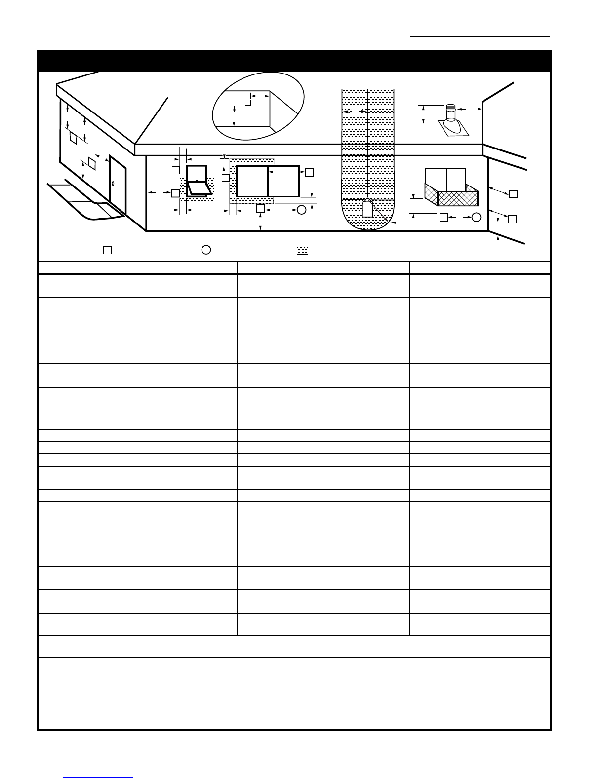
General Venting Information - Termination Location
INSIDE
CORNER DETAIL
G
V
D
E
V
A
H
N
N
CFM145a
B
V
L
VENT TERMINATION AIR SUPPLY INLET
V
C
Fixed
Fixed
V
Closed
Closed
F
Operable
V
B
B
V
Operable
B
X
B
Fixed
Closed
V
A
V
B
X
J
AREA WHERE TERMINAL IS NOT PERMITTED
Canadian Installations
G
V
M
I
1
K
V
US Installations
G
X
V
A
2
A = Clearance above grade, veranda, porch, 12 inches (30cm) 12 inches (30cm)
deck, or balcony
B = Clearance to window or door that may be 6 in (15cm) for appliances 6 in (15cm) for appliances
opened < 10,000Btuh (3kW), 12 in (30cm) < 10,000 Btuh (3kW), 9 in
for appliances > 10,000 Btuh (3kW) and (23cm) for appliances > 10,000
< 100,000 Btuh (30kW), 36 inches (91cm) Btuh (3kW) and < 50,000 Btuh
for appliances > 100,000 Btuh (30kW) (15kW), 12 in (30cm) for
appliances > 50,000 Btuh (15kW)
C = Clearance to permanently closed window 12” (305mm) recommended to 12” (305mm) recommended to
prevent window condensation prevent window condensation
D = Vertical clearance to ventilated soffit located
above the terminal within a horizontal 18” (458mm) 18” (458mm)
distance of 2 feet (610mm) from the center
line of the terminal
E = Clearance to unventilated soffit 12” (305mm) 12” (305mm)
F = Clearance to outside corner see next page see next page
G = Clearance to inside corner (see next page) see next page see next page
H = Clearance to each inside of center line 3 feet (91cm) within a height of 15 feet 3 ft (91cm) within a height of 15ft
extended above meter/regulator assembly above the meter/regulator assembly above the meter/regulator assy
I = Clearance to service regulator vent outlet 3 feet (91cm) 3 feet (91cm)
J = Clearance to nonmechanical air supply inlet 6 inches (15cm) for appliances < 10,000 6 inches (15cm) for appliances
to building or the combustion air inlet to any Btuh (3kW), 12 inches (30cm) for < 10,000 Btuh (3kW), 9 inches
other appliances appliances > 10,000 Btuh (3kW) and < (23cm) for appliances > 10,000
100,000 Btuh (30kW), 36 inches (91cm) Btuh (3kW) and < 50,000 Btuh
for appliances > 100,000 Btuh (30kW) (15kW), 12 inches (30cm) for
appliances > 50,000 Btuh (15kW)
K = Clearance to a mechanical air supply inlet 6 feet (1.83m) 3 feet (91cm) above if within 10
feet (3m) horizontally
L = Clearance above paved sidewalk or paved 7 feet (2.13m)† 7 feet (2.13m)†
driveway located on public property
M = Clearance under veranda, porch, deck or 12 inches (30cm)c 12 inches (30cm)†
balcony
N = Clearance above a roof shall extend a minimum of 24” (610mm) above the highest point when it passes through the roof
surface, and any other obstruction within a horizontal distance of 18” (450mm).
1 In accordance with the current CSA-B149 Installation Codes
2 In accordance with the current ANSI Z223.1/NFPA 54 National Fuel Gas Codes
† A vent shall not terminate directly above a sidewalk or paved driveway which is located between two single family dwellings and serves
both dwellings
‡ only permitted if veranda, porch, deck or balcony is fully open on a minimum 2 sides beneath the floor:
NOTE: 1. Local codes or regulations may require different clearances.
2. The special venting system used on Vermont Castings Direct Vent Stoves are certified as part of the appliance, with clearances
tested and approved by the listing agency.
Fig. 9 Vent termination clearances.
10
10
20003456
Vermont Castings Stardance Direct Vent/Natural Vent Gas Heaterr
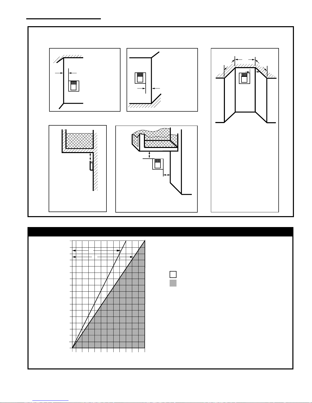
Termination Clearances
Termination clearances for buildings with combustible and noncombustible exteriors.
Inside Corner
Outside Corner
Recessed Location
A
V
Balcony with no side wall
G =
Combustible&
Noncombustible
12"(305mm)
A =
Combustible
6"(152mm)
Noncombustible
2"(50mm)
G
V
B =
Combustible
6"(152mm)
V
Noncombustible
2"(50mm)
B
Balcony with perpendicular side wall
H
V
Combustible &
Noncombustible
H = 24"(610mm)
J = 20"(508mm)
J
C
C
E
V
C = Maximum depth of 48"
(1219mm) for recessed
location.
D = Minimum width for back wall
of a recessed location.
Combustible 38"(965mm)
Noncombustible 24"(610mm)
E = Clearance from corner in
recessed location.
Combustible 6"(152mm)
Noncombustible 2"(50mm)
D
584-14
Fig. 10 Termination clearances.
Venting Requirements - Natural Vent Only
36
34
32
30
28
26
24
22
20
18
16
14
Vertical Run (in feet)
12
10
8
6
4
(Measured from top of the unit before any elbow)
2
1 2 4 6 8 10 12 14 16 18 20 22 24
Fig. 11 Vent termination window - Natural Vent ONLY.
A
B
Horizontal Run (in feet)
Venting Runs
NOTE: When venting staight vertical, without any
elbow, a minimum of 8 ft. vertical is required
off the top of the stove.
= Acceptable venting configuration
= Unacceptable venting configuration
A: Vertical installations up to 36 feet (12m) in
height. Up to an 18 ft. horizontal vent run can be
installed within the vent system using a
maximum of two 90-degree elbows or four
45-degree elbows.
B: Vertical installations up to 36 feet (12m) in
height. Up to a 24 ft. horizontal vent run can be
installed within the vent system using a
maximum of two 45-degree elbows.
(Ratio = 2/3, Hor./Vert.)
FP567b
NOTE: When using the FSDHAG, the restrictor plate
supplied with the stove is not used.
20003456
11

Vermont Castings Stardance Direct Vent/Natural Vent Gas Heater
Venting Requirements and Options -
Direct V ent ONLY
Approved Vent System Components
The Stardance Heater must be vented to the outdoors
through an adjacent exterior wall or through the roof.
The venting system must be comprised of the appropriate listed venting components specified on this page.
These parts are available from DuraVent Corporation or
your Vermont Castings Majestic Products Dealer.
See Figure 4 for dimensions relevant to the standard
minimum-vent kits.
Simpson DuraVent Components
Minimum Horizontal Vent Kit 2792
Starter Pipe Assembly (incl. inner & outer sections)
2768*
90° Elbow, Blk. 990B*
45° Elbow, Gal. 945
6” Straight, Blk. 908B*
9” Straight, Blk. 907B
11” - 14⁵⁄₈” Adjustable Straight Section 911B
12” Straight 906
24” Straight 904B*
36” Straight 903B
48” Straight 902
Horizontal Vent Cap 984*
Wall Plate* 940
Vinyl Siding Shield 950
Snorkel Termination - 14” 982
Snorkel Termination - 36” 981
Wall Strap 988
Cathedral Ceiling Support Box 941
Storm Collar 953
Firestop Spacer 963
Flashing 0/12 - 6/12 943
Flashing 6/12 - 12/12 943S
Vertical Termination Cap 991
*Included in Minimum Horizontal Vent Kit #2792
All DuraVent Straight vent pipe sections have a net
length 1¹⁄₂” (37mm) less than the nominal dimension;
i.e., a 6” (152mm) Straight pipe section has an
effective length of 4¹⁄₂” (115mm).
CFM Vent Components
The following kits are available to meet the needs of
most installations. All pipe has a 7" outer diameter and
includes a 4" diameter inner section. A (CG) designation indicates the part is finished in Charcoal Gray
paint. Consult your dealer about other vent parts that
may be appropriate to complete the installation.
Min. Through the Wall Vent Kit 7TFSMSK
(1) 90-Degree Elbow (CG)
(1) 24" Straight pipe (CG)
(1) 36" Straight pipe (CG)
(1) Side Wall Termination
(1) Firestop
(1) Zero-clearance sleeve
(1) Hardware package
(1) Finishing plate (CG)
(1) Finishing collar (CG)
(4) Polished Brass flue pipe rings
Through the Wall Vent Kit 7TFSDVSK
(1) 90-Degree Elbow (CG)
(1) 24" Straight pipe (CG)
(1) 48" Straight pipe (CG)
(1) Side Wall Termination
(1) Firestop
(1) Zero-clearance sleeve
(1) Hardware package
(1) Finishing plate (CG)
(1) Finishing collar (CG)
(4) Polished Brass flue pipe rings
Through the Wall Vent Kit for
Below-Grade Termination 7TFSDVSKS
Includes all of the above parts plus
(1) Snorkel Termination
Vertical Termination Kit, 1/12-6/12 Pitch 7TDVSKVA
(1) Combination Horizontal Offset / Roof Support
(1) Vertical Termination
(1) Storm Collar
(1) 1/12-6/12 Flashing
(1) Finishing Plate (CG)
(1) Finishing Collar (CG)
(1) Polished Brass Flue Pipe Ring
(1) Hardware Package
Vertical Termination Kit, 7/12-12/12 Pitch 7TDVSKVB
(1) 7/12 - 12/12 Flashing
and all of the other Vertical Termination parts.
Vertical Termination, Flat Roof 7DVSKVF
(1) Flat Flashing
and all of the other Vertical Termination parts.
Twist Lock 24" Straight Pipe (CG) 7TFSDVP24
(1) 24" Non-adjustable Pipe
(1) Polished Brass Flue Pipe Ring
Twist Lock 48" Straight Pipe (CG) 7TFSDVP48
(1) 48" Nonadjustable Pipe
(1) Polished Brass Flue Pipe Ring
Twist Lock 45-Degree Elbow (CG) 7TFSDVT45
for vertical offsets
(1) 45-degree Elbow
(1) Polished Brass Flue Pipe Ring
Draft Hood Adapter FSDHAG
NV Stove Kit 7FSSK
(1) 7” Diameter Polished Brass Trim Ring
(1) 48” Nonadjustable Pipe (CG)
(1) 24” Nonadjustable Pipe (CG)
(1) Finishing Plate
(1) Finishing Collar (CG)
(1) 90 Degree Elbow (CG)
Stove Kit 7FSDHASK
Includes all parts in the 7FSSK plus the Draft Hood Adapter
FSDHAG
Combination Offset/Roof Support 7DVCS
Attic Insulation Shield 7DVAIS
7" Charcoal Gray Pipe Rings, (4) 7FSDRG
7" Polished Brass Pipe Rings (4) 7FSDRP
Wall Thimble 942G
NOTE: Direct vent pipe may be used on the Natural
Vent system from the top of the draft hood adapter to
the ceiling.
12
12
20003456
Vermont Castings Stardance Direct Vent/Natural Vent Gas Heaterr
Assembly Procedures
WARNING
Failure to position the parts in
accordance with these diagrams or
failure to use only parts specifically
approved for use with this heater may result in
property damage or personal injury.
This heater and components are heavy. Have
help available for assembly.
Tools Required
• Phillips screwdriver (stub) • power drill
• utility knife • reciprocating saw
• metal drill bit: size 28 (.140"/3.5mm)
Parts Bag Contents:
• On-Off switch, housing, and wiring harness
• (3) Phillips round-head bolts, 1/4"- 20 x 1/2"
• (2) #8 x 1/2” sheet metal screws
• 1 Bag of Lava Rocks
• 1 Wire tie
• 1 Tube of Vent Gasket Cement
• 1 Vent Restrictor Plate, 2¹⁄₄" inside diameter
• Owner Registration Card
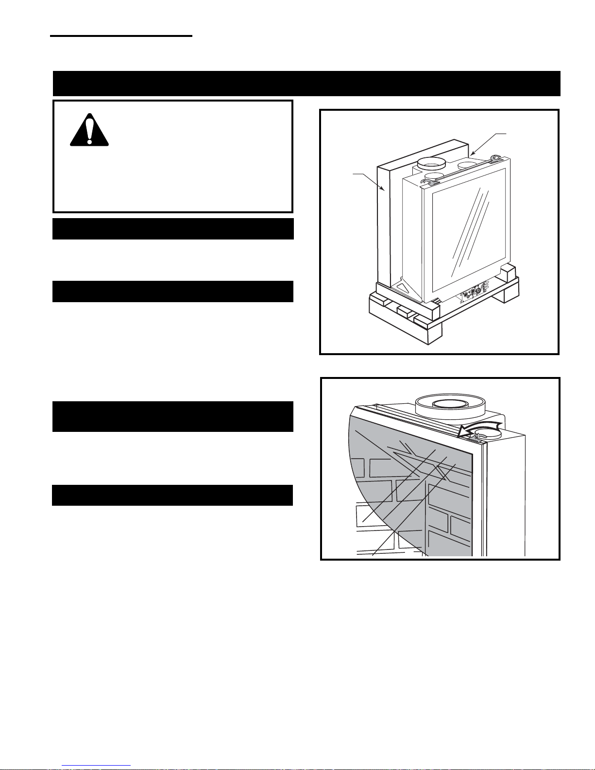
Rear
Skirt
Carton
Fig. 12 Stardance firebox as shipped.
Remove any
packing
material
ST469
Unpack the SDV30 Firebox, Logset and
Stove Shell
Cut the shipping straps and remove the Rear Skirt from
its carton. Remove any packing material from the top
of the firebox, Figure 12. Do not remove the firebox
from the shipping pallet yet.
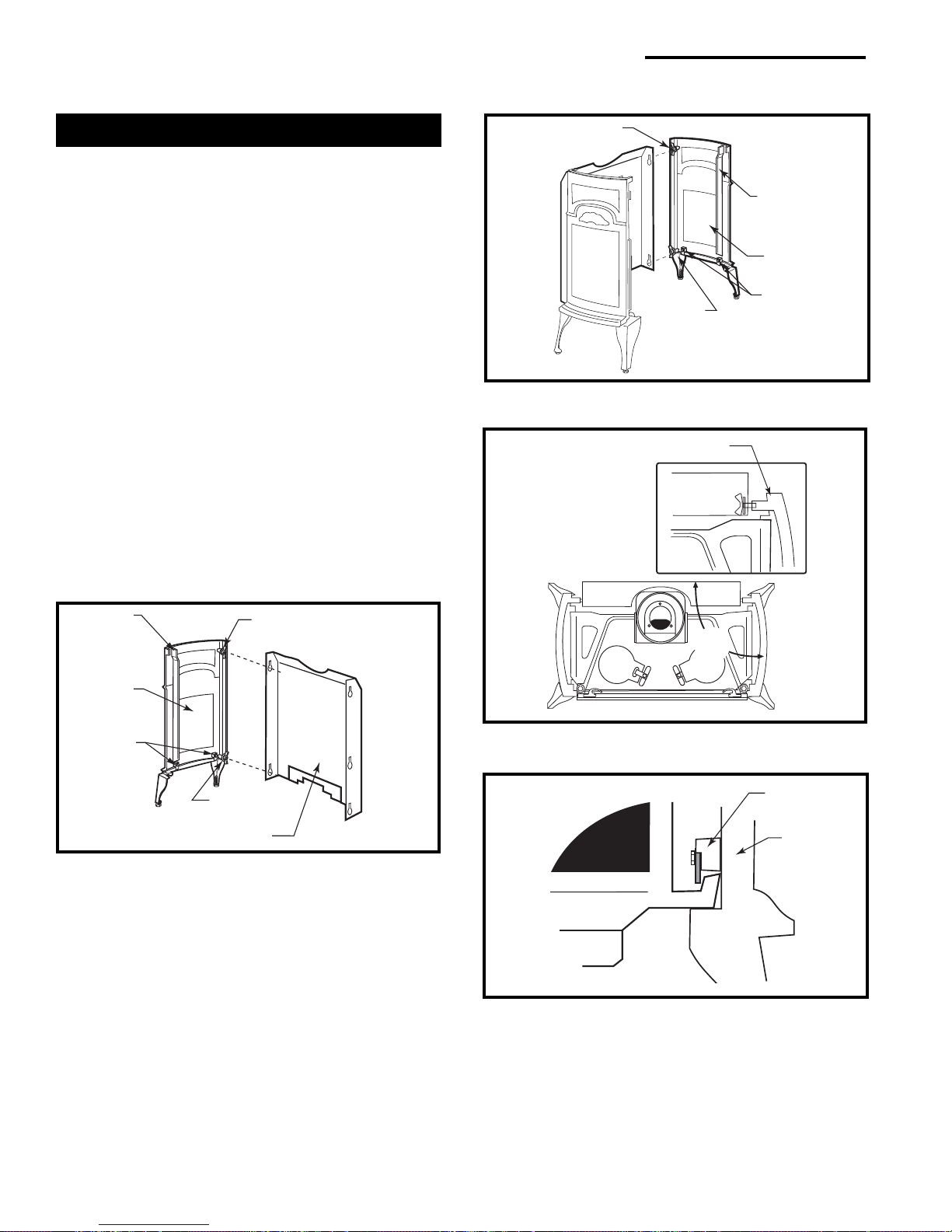
Remove the Log Set
The Log Set is inside the firebox in a protective package. The Glass Panel must be removed to install the
Log Set in the firebox.
• Swing open the swiveling latches at the top left and
right corners of the glass frame. (Fig. 13)
• Pull the top edge of the glass and frame assembly
away from the firebox, and lift it off its supports on
the bottom of the firebox face. Place the assembly
out of the way on a flat, padded surface such as a
counter protected by a towel.
•Take the log set and all other loose parts (4” sleeve)
out of the firebox, and set them aside in a protected
spot, for installation after the venting is complete.
NOTE: Verify the two relief doors (located on top of
the firebox) are properly seated on the gasket. The
doors should sit flush on the gasket, and should lift
easily from the seal around the opening.
ST208
Fig. 13 Swivel the latches to release the glass frame.
Unpack the cast iron stove shell parts from the shipping
carton (separate carton). Inspect each part for shipping
damage and set it aside on a protective surface.
Porcelain enamelled surfaces are fragile. Handle
porcelain enamelled castings with care.
Before you begin assembly, read this section of the
manual to familiarize yourself with the procedures. The
installation will be easiest if you follow the steps in the
order presented.
20003456
13
Vermont Castings Stardance Direct Vent/Natural Vent Gas Heater
Shell Assembly
1. Attach the Rear Skirt to the Left End plate by aligning
the key holes with the two wingbolts in the side. If
necessary, turn the wingbolts to orient the blades
vertically. (Fig. 14) Slide the skirt downward to
engage it behind all three washers on the side plate
bolts and then tighten both wingbolts.
2. Attach the Right Side Plate to the Rear Skirt. (Fig.
15) Move this assembly close to the stove's final
position. Align the two side plates at right angles to
the Back Panel as in Figure 16.
NOTE: The firebox is shipped with three bolts and
spacers on the bottom to prevent any damage to the
bottom assembly. The two front bolts should be
removed after installation. Use a 7/16” wrench.
3. Lift the firebox assembly and slide it into the shell.
The base of the firebox should rest on the side
support shelves. (Fig. 16 & 17) The side plates
interlock with the firebox by use of a pair of steel tabs
that engage with the ribs on the base of the firebox.
(Fig. 17) Properly positioned, the firebox will be level
and locked in place. If not, adjust the levelling screw
in the foot of each leg as needed.
Wingbolt
Side Rib
Right Side
Steel Tabs
Wingbolt
ST471
Fig. 15 Fasten right end to rear skirt.
Right Side
Side Rib
Left Side
Steel Tabs
Fig. 14 Fasten left end to rear skirt.
Wingbolt
Wingbolt
Rear Skirt
ST470
90°
ST472
Fig. 16 Align both sides with the rear skirt.
Steel Tab
Side Plate
Support Shelf
Base
ST125
Fig. 17 Install firebox assembly.
14
14
20003456
 Loading...