

Vermont Castings SDDVTCBSB, SDDVTBSSB, SDVTSCCB, SDDVTBMSB, SDDVTBDSB Installation & Operating Manual
...
S
Installation & Operating Manual
DANGER
Installation and Appliance Setup - Care and Operation
INSTALLER: Leave this manual with party responsible for use and operation.
OWNER: Retain this manual for future reference.
Call your dealer for questions on Installation, Operation, or Service.
NOTICE: SAVE THESE INSTRUCTIONS
SDDVT Series Stardance
®
Direct Vent Gas Heater
Models:
SDDVTCBSB, SDDVTBSSB, SDDVTBDSB,
SDDVTBMSB, SDVTSCCB, SDVTSCBS,
SDVTSCBD, SDVTSCBM
WARNING:
FIRE OR EXPLOSION HAZARD
Failure to follow safety warnings exactly could
result in serious injury, death or property damage.
• Donotstoreorusegasolineorotherammable
vapors and liquids in the vicinity of this or any
other appliance.
• WHAT TO DO IF YOU SMELL GAS
– Do not try to light any appliance.
– Do not touch any electrical switch; do not use
any phone in your building.
– Leave the building immediately.
– Immediately call your gas supplier from a
neighbor's phone. Follow the gas supplier's
instructions.
– If you cannot reach your gas supplier, call the
redepartment.
• Installation and service must be performed
by a qualied installer,service agency or the
gas supplier.
WARNING: Improper installation, adjustment,
alteration, service or maintenance can cause injury or
property damage. Refer to this manual. For assistance
oradditionalinformationconsultaqualiedinstaller,
service agency or the gas supplier.
CERTIFIED
AFETY BARRIER
HOT GLASS WILL
CAUSE BURNS.
A barrier designed to reduce the risk of burns from
the hot viewing glass is provided with this
appliance and shall be installed.
1
DO NOT TOUCH GLASS
UNTIL COOLED.
NEVER ALLOW CHILDREN
TO TOUCH GLASS.
This appliance may be installed in an aftermarket,*
permanently located, manufactured home (USA only)
or mobile home, where not prohibited by local codes.
This appliance is for use only with the type of gas
indicated on the rating plate. This appliance is not
convertibleforusewithothergases,unlessacertied
kit is used.
* Aftermarket: Completion of sale, not for purpose of
resale, from the manufacturer.
3-90-20306760Vermont Castings • Stardance SDDVTSB Installation Manual_R10 • 04/18

PLEASE READ THE INSTALLATION & OPERATING INSTRUCTIONS BEFORE USING APPLIANCE.
Thank you and congratulations on your purchase of a Vermont Castings stove.
IMPORTANT: Read all instructions and warnings carefully before starting installation. Failure to follow these instructions may result in a
possible re hazard and will void the warranty.
Table of Contents
Important Safety Information ......................................... 3
Massachusetts residents only ................................................... 4
Pre-Installation................................................................. 5
Stove Dimensions ..................................................................... 5
Installation Requirements .........................................................6
Clearance Requirements .......................................................... 6
Parallel Installation .................................................................... 7
Corner Installation ..................................................................... 7
Wall and Ceiling Clearances .....................................................7
Hearth Requirements ............................................................... 7
Gas Specications .................................................................... 8
Gas Inlet and Manifold Pressures ............................................. 8
High Elevations ......................................................................... 8
Horizontal Termination ............................................................. 8
Vertical Termination ...................................................................9
Restrictor Plate Adjustment for Extended Pipe Runs...............9
Vent Termination Clearances .................................................. 10
General Venting Information – Termination Location .............. 11
Termination Clearances. ......................................................... 12
Assembly & Installation ................................................ 13
Venting Requirements and Options ........................................13
Assembling the Stove ............................................................ 14
Install the Optional Fan – SDDVT Models (Millivolt Only) ������������ 14
Venting System Assembly.......................................................16
Important Safety Information...................................................16
Before You Start ...................................................................... 16
Install the Vent Adapter Pipe ................................................... 17
Assemble Slip Sections ..........................................................18
Secure the Vent Sections........................................................18
Disassemble Vent Sections ....................................................19
Horizontal Termination Cap ..................................................... 19
Divert Roof Run-off .................................................................20
Vertical Side Wall Installation .................................................. 20
Vent Termination Below Grade ...............................................21
Vertical Through-The-Roof Application/installation ................. 22
Venting System Assembly - Natural Vent................................23
Install Log Set ......................................................................... 24
Install ON/OFF Switch – SDDVT Models (Millivolt Only) ........ 26
Thermostat Connection (optional)...........................................26
Signature Command® System (SC) ....................................... 26
Junction Box Wiring ................................................................ 27
Command Center Wall Installation .........................................27
Wall Switch Installation ..........................................................27
Connect the Gas Supply Line ................................................. 28
Burner Information .................................................................. 28
Signature Command Wiring Diagram ..................................... 29
Install the Safety Barrier..........................................................30
Install the Mesh and Grill ........................................................30
Operating Instructions .................................................. 31
Your First Fire .........................................................................31
Pilot and Burner Inspection ..................................................... 31
Flame & Temperature Adjustment ........................................... 31
Flame Characteristics ............................................................. 31
Lighting and Operating Instructions ........................................ 32
Troubleshooting ......................................................................33
Read Before Lighting .............................................................. 34
Signature Command Operating Instructions .............. 36
Features .................................................................................. 36
Battery Installation ..................................................................36
System Conguration/Setup ................................................... 36
Operating instructions .................................................. 38
Turning on the stove ...............................................................38
Command Center Operations ................................................. 38
Initialization and Setting up ..................................................... 39
Functions and Operations ....................................................... 40
Safety Features.......................................................................43
Troubleshooting ............................................................ 44
Troubleshooting – SIGNATURE COMMAND SYSTEM .......... 44
Fuel Conversion ............................................................ 46
Cleaning & Maintenance ............................................... 51
Annual System Inspection ......................................................51
Logset and Burner / Cleaning and Inspection ......................... 51
Care of Cast Iron.....................................................................51
Cleaning the Glass..................................................................51
Gasket Replacement ..............................................................52
Inspect the Vent System Annually........................................... 52
Check the Gas Flame Regularly ............................................. 52
Glass Replacement.................................................................52
Wiring Diagrams ............................................................ 53
Service Parts List .......................................................... 55
Optional Accessories .................................................... 59
Limited Lifetime Warranty ............................................ 60
= Contains updated information
2
3-90-20306760Vermont Castings • Stardance SDDVTSB Installation Manual_R10 • 04/18

Important safety information
The Stardance Direct Vent Room heater, Model Nos. SDDVTCBSB,
SDDVTBSSB, SDDVTBDSB, SDDVTBMSB, SDVTSCCB,
SDVTSCBS, SDVTSCBD, SDVTSCBM, is a vented gas appliance
listed to the ANSI Standard Z21.88-2014 and CSA 2.33-2014 for
Vented Room heaters, and CSA 2.17-M91, Gas-Fired Appliances
For Use at High Altitudes.
The installation of the Stardance Direct Vent Room heater must
conform with local codes, or in the absence of local codes, with
National Fuel Gas Code, ANSI Z22.1/NFPA 54 — latest edition and
CSA B-149.1 Installation Code. (EXCEPTION: Do not derate this
appliance for altitude. Maintain the manifold pressure at 3.5 inches
w.c. for Natural Gas and 10 inches w.c. for LP gas at maximum
input.)
This appliance is only for use with the type of gas indicated on the
rating plate. This appliance is not convertible for use with other
gases unless a certied kit is used.
Installation and replacement of gas piping, gas utilization
equipment or accessories, and repair and servicing of equipment
shallbeperformedonlybyaqualiedagency,preferablyNFIor
WETT(Canada)certied.Theterm“qualiedagency"meansany
individual,rm,corporation,orcompanythateitherinperson
or through a representative is engaged in and is responsible
for (a) installation or replacement of gas piping, or (b), the
connection, installation, repair, or servicing of equipment,
who is experienced in such work, familiar with all precautions
required, and has complied with all the requirements of the
authority having jurisdiction.
The Stardance Direct Vent Room heater should be inspected
beforeuseandatleastannuallybyaqualiedserviceagency.Itis
imperative that control compartments, burners, and circulating
air passageways of the appliance be kept clean.
The Stardance Direct Vent Room heater and its individual shut-off
valve must be disconnected from the gas supply piping during any
pressure testing of that system at test pressures in excess of 1/2
psig (3.5 kPa).
The Stardance Direct Vent Room heater must be isolated from the
gas supply piping system by closing its individual manual shutoff
valve during any pressure testing of the gas supply piping system
at test pressures equal to or less than 1/2 psig.
An accessible tap is located above the pilot/On-Off knob for checking
the inlet pressure.
‘Direct Vent’ describes a sealed combustion system in which
incoming outside air for combustion and outgoing exhaust enter
and exit through two separate concentric passages within the same
sealed vent system. The system does not use room air to support
combustion. The Direct Vent system permits the gas appliance to
be vented directly to the outside atmosphere through the side of the
house or vertically through the roof. Conventional venting systems
(Natural Vent) take air from the room for combustion and vent the
exhaust vertically through the roof to the atmosphere.
This appliance is approved for bedroom installations in the U.S.
and Canada.
This appliance may be installed in an aftermarket* manufactured
(mobile) home, where not prohibited by state or local codes.
WARNING: Operation of this heater when not connected to a
properly installed and maintained venting system can result in
carbon monoxide (CO) poisoning and possible death.
The Stardance Direct Vent Room heater, when installed, must
be electrically grounded in accordance with local codes or, in the
absence of local codes, with the National Electrical Code ANSI/NFPA
70, (latest edition), or of the current Canadian Electrical Code C22.1.
Due to high temperatures this appliance should be located out
oftrafcandawayfromfurnitureanddraperies.
WARNING: This appliance is hot while in operation. Keep
children, clothing, and furniture away. Contact may cause
burns or ignition of combustible materials.
Children and adults should be alerted to the hazards of high
surface temperatures and should stay away to avoid burns or
clothing ignition.
Young children should be carefully supervised when they are
in the same room as the appliance. Toddlers, young children
and others may be susceptible to accidental contact burns. A
physical barrier is recommended if there are at risk individuals
in the house. To restrict access to a stove or stove, install an
adjustable safety gate to keep toddlers, young children and other
at risk individuals out of the room and away from hot surfaces.
Clothingorother ammable materials shouldnotbeplaced
on or near the appliance.
Any safety screen, glass or guard removed for servicing an
appliance must be replaced prior to operating the appliance.
The appliance area must be kept clear and free from combustible
materials,gasoline,andotherammablevaporsandliquids.
The ow of combustion and ventilation air must not be
obstructed. The installation must include adequate accessibility
and clearance for servicing and proper operation.
WARNING: Do not operate the Room heater with the glass panel
removed, cracked or broken. Replacement of the panel should
bedonebyalicensedorqualiedserviceperson.
Do not use this appliance if any part has been under water.
Immediatelycallaqualiedservicetechniciantoinspectthe
appliance and to replace any part of the control system and
any gas control which has been under water.
Do not burn wood, trash or any other material for which this
appliance was not designed. This appliance is designed to
burn either natural gas or propane only.
Thisgasappliancemustnotbeconnectedtoachimneyue
serving a separate solid-fuel burning appliance.
CAUTION: Label all wires prior to disconnection when servicing
controls. Wiring errors can cause improper and dangerous
operation.
Verify proper operation after servicing.
* Aftermarket: Completion of sale, nor for purpose of resale, from
the manufacturer�
3
3-90-20306760Vermont Castings • Stardance SDDVTSB Installation Manual_R10 • 04/18

Requirements for the Commonwealth of
Massachusetts
All gas tting and installation of this heater shall only be done
by a licensed gas tter or licensed plumber.
For all side wall horizontally vented gas fueled equipment
installed in every dwelling, building or structure used in whole
or in part for residential purposes, including those owned or
operated by the Commonwealth and where the side wall
exhaust vent termination is less than seven (7) feet above
nished grade in the area of the venting, including but not
limited to decks and porches, the following requirements
shall be satised:
Installation of Carbon Monoxide Detectors
At the time of installation of the side wall horizontal vented
gas fueled equipment, the installing plumber or gas tter shall
observe that a hard wired carbon monoxide detector with an
alarm is installed on each additional level of the dwelling,
building or structure served by the side wall horizontal
vented gas fueled equipment. It shall be the responsibility
of the property owner to secure the services of qualied
licensed professionals for the installation of hard wired carbon
monoxide detectors.
In the event that the side wall horizontally vented gas fueled
equipment is installed in a crawl space or an attic, the hard
wired carbon monoxide detector with alarm and battery
back-up may be installed on the next adjacent oor level.
In the event that the requirements of this subdivision can not
be met at the time of completion of installation, the owner shall
have a period of thirty (30) days to comply with the above
requirements; provided, however, that during said thirty (30)
day period, a battery operated carbon monoxide detector with
an alarm shall be installed.
Approved Carbon Monoxide Detectors
Each carbon monoxide detector as required in accordance
with the above provisions shall comply with NFPA 720 and
ANSI/UL 2034 listed and IAS certied.
Signage
Ametalorplasticidenticationplateshallbepermanently
mounted to the exterior of the building at a minimum
height of eight (8) feet above grade directly in line with
the exhaust vent terminal for the horizontally vented gas
fueled heating appliance or equipment. The sign shall
read, in print size no less than one-half (1/2) inch in size,
“GASVENTDIRECTLYBELOW,KEEP CLEAROFALL
OBSTRUCTIONS".
Inspection
The state or local gas inspector of the side wall horizontally
vented gas fueled equipment shall not approve the installation
unless, upon inspection, the inspector observes carbon
monoxide detectors and signage installed in accordance with
the provisions of 248 CMR 5.08(2)(a)1 through 4.
Exemptions
The following equipment is exempt from 248 CMR 5.08(2)
(a)1 through 4:
• The equipment listed in Chapter 10 entitled “Equipment
Not Required To Be Vented" in the most current edition of
NFPA 54 as adopted by the Board; and
• Product Approved side wall horizontally vented gas fueled
equipment installed in a room or structure separate from
the dwelling, building or structure used in whole or in part
for residential purposes.
Manufacturer Requirements
Gas Equipment Venting System Provided
When the manufacturer of Product Approved side wall
horizontally vented gas equipment provides a venting system
design or venting system components with the equipment,
the instructions provided by the manufacturer for installation
of the equipment and the venting system shall include:
• Detailed instructions for the installation of the venting
system design or the venting system components; and
• A complete parts list for the venting system design or
venting system.
Gas Equipment Venting System NOT Provided
When the manufacturer of a Product Approved side wall
horizontally vented gas fueled equipment does not provide
the parts for venting the ue gases, but identies “special
venting systems", the following requirements shall be
satised by the manufacturer:
• The referenced “special venting system" instructions shall
be included with the appliance or equipment installation
instructions; and
• The “special venting systems" shall be Product Approved
by the Board, and the instructions for that system shall
include a parts list and detailed installation instructions.
A copy of all installation instructions for all Product Approved
side wall horizontally vented gas fueled equipment, all venting
instructions, all parts lists for venting instructions, and/or all
venting design instructions shall remain with the appliance
or equipment at the completion of the installation.
Stardance Direct Vent
Certiedto:ANSIZ21.88-2014/CSA2.33-2014Vented
Gas Heaters
4
Proposition 65 Warning: Fuels used in gas, woodburning or oil fired appliances, and the products of
combustion of such fuels, contain chemicals known to
the State of California to cause cancer, birth defects and
other reproductive harm.
California Health & Safety Code Sec. 25249.6
3-90-20306760Vermont Castings • Stardance SDDVTSB Installation Manual_R10 • 04/18

Stardance Direct Vent Stove Dimensions
7" Outer Dia.
Weight: Fully assembled; 202 lbs.
See Figure 3 & 4 for Flue Collar Centerline Dimensions.
Flue Collar
25-1/2"
(648 mm)
(73 mm)
C
L
2-7/8”
12-5/8”
(321 mm)
26-3/4"
(680 mm)
C
L
(178 mm)
Supply Inlet
3"
(76 mm)
14-1/2"
(355 mm)
Figure 1 - Stardance dimensions.
5
3-90-20306760Vermont Castings • Stardance SDDVTSB Installation Manual_R10 • 04/18
Installation Requirements
!
appliance and shall be installed.
A
B
E
C
D
!
The installation must conform with local codes or, in the
absence of local codes, with the National Fuel Gas Code,
ANSI Z223.1/NFPA 54 – latest edition. (EXCEPTION: Do
not derate this appliance for altitude. Maintain the manifold
pressure at 3.5" w.c. for Natural Gas, and 10" w.c. for
Propane).
In Canada, installation must be in accordance with the current
CSA B-149.1 Installation Codes and/or local codes.
The installation should be done by a qualied service person
who is familiar with the building codes and installation
techniques appropriate for your area to accomplish a safe
and effective installation.
Your dealer or your local gas supplier will be able to refer a
qualied service person.
WARNING
Due to high temperatures, the heater should be located
out of trafc and away from furniture and draperies.
The surface of the Heater Is hot when it is in use. Young
children should be watched carefully when they are in the
same room when the Heater is in use, and they should
be taught to avoid the hot surface. Keep any objects that
can burn well away from the Heater, and observe the
recommended clearances that follow.
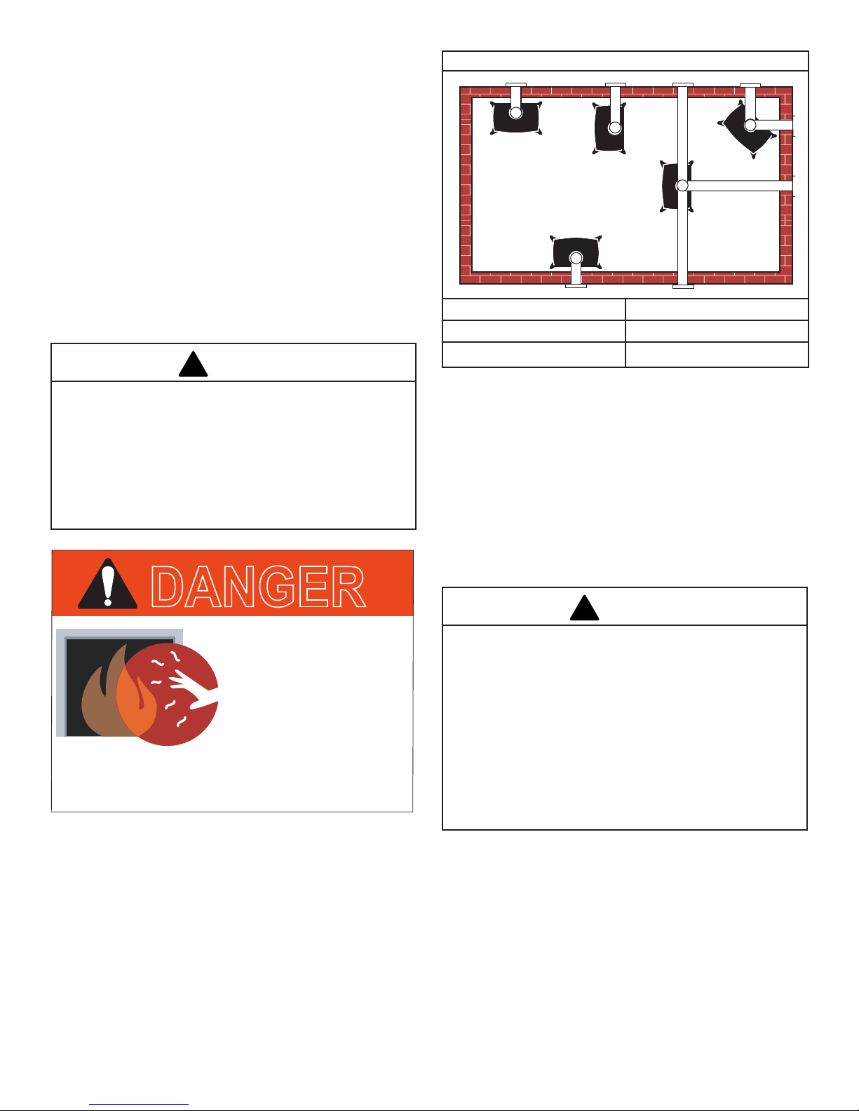
Direct Vent System Only
A. Flat on corner wall D. Cross Corner
B. Room Divider E. Flat on wall
C. Island
Figure 2 - Possible stove locations.
Clearance Requirements
Minimum Clearances to Combustible Materials
Measure side clearances as shown in Figures 3, 4 and 5
from the outer edge of the cast iron stove top. Measure rear
clearances from the outermost surface of the steel rear skirt.
The Stardance heater is approved for installation into
an alcove constructed of combustible materials to the
dimensions and clearances shown on the next page.
The same clearances apply in a standard parallel installation.
DANGER
HOT GLASS WILL
CAUSE BURNS.
DO NOT TOUCH GLASS
UNTIL COOLED.
NEVER ALLOW CHILDREN
TO TOUCH GLASS.
A barrier designed to reduce the risk of burns from
the hot viewing glass is provided with this
In choosing a location for the stove, consider:
• The location of outside walls;
• Where additional heat is needed:
• Where family members gather most often;
• The vent system requirements.
NOTE: We do not recommend the use of wallpaper next to
this stove. Over time, radiant heat may cause the wallpaper
to shrink, or may adversely affect the binders in the wallpaper
adhesive.
WARNING
• Always maintain required clearances (air spaces) to
nearby combustibles to prevent re hazard. Do not
ll air spaces with insulation. All venting components
must maintain a 1" (25 mm) clearance to combustible
materials. The gas appliance and vent system must
be vented directly to the outside of the building and
never be attached to a chimney serving a separate
solid fuel or gas-burning appliance.
• Refer to the manufacturer’s instructions included
with the venting system for complete installation
procedures.
6
3-90-20306760Vermont Castings • Stardance SDDVTSB Installation Manual_R10 • 04/18
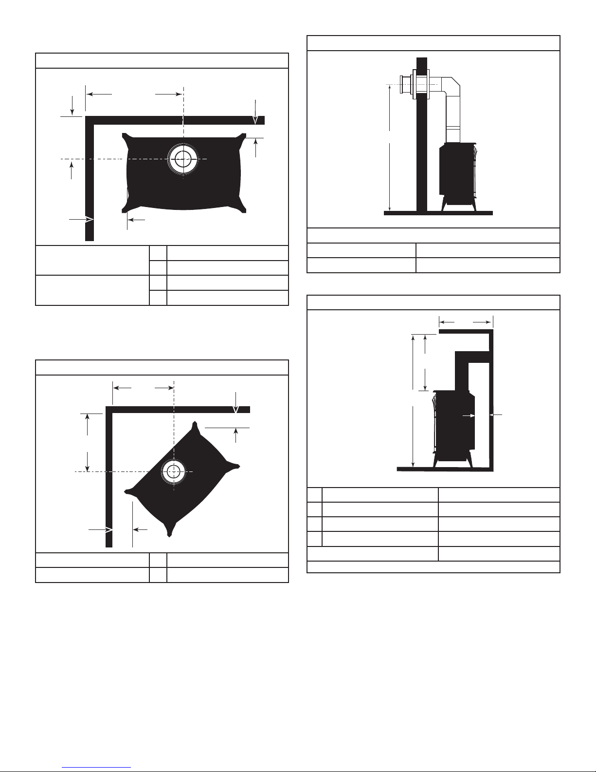
Parallel Installation
Wall Centerline from Floor
Minimum Clearance and Flue Centerline
C
L
C
D
C
L
A
B
Stove Clearances
Pipe Centerlines
Figure 3 - Parallel installation, minimum back and side
clearances,anduecenterlines.
A 4" (102 mm)
B 4" (102 mm)
C 15-1/2" (395 mm)
D 9" (229 mm)
Direct Vent Only
A
Effective Minimum
Wall Thimble 56" (1480 mm) (HHT Pipe)
Centerline 52" (1378 mm) DuraVent Pipe)
Figure 5 - Minimum wall centerline.
Wall & Ceiling Clearances
Direct Vent Only
D
Corner Installation
Minimum Clearance and Flue Centerline
B
A
B
A
Stove Clearances
Pipe Centerlines
Figure 4 - Corner installation, minimum corner clearances
anduecenterline.
A 4" (102 mm)
B 14-1/2" (370 mm)
B
C
A
A Rear Wall 4" (102 mm)
B Minimum Clearance 45-1/4" (1154 mm)
C Minimum Alcove Height 72" (1830 mm)
D Maximum Alcove Depth 48" (1220 mm)
Sidewall Clearance 4" (102 mm)
* needed for installing DuraVent Minimum Vent Kit #2792 or HHT Minimum Vent Kit #SLP-FSSK.
Figure 6 - Dimensions and clearances to ceiling or alcove.
Hearth Requirements
The Stardance heater must be installed on rigid ooring.
When the heater is installed directly on any combustible
surface other than wood ooring, a metal or wood panel
extending the full width and depth of the unit must be used
as the hearth. There are no other hearth requirements.
7
3-90-20306760Vermont Castings • Stardance SDDVTSB Installation Manual_R10 • 04/18
GasSpecications
!
20
19
18
16
15
14
13
12
11
10
9
8
7
6
5
4
3
2
1
0
1 2 3 4 5 6 7 8 9 10 11 12 13 14 15 16 17 18 19 20
Vertical Run (in feet)
(Measured from the appliance flue collar to the top of the vent pipe.)
Horizontal Run (in feet)
21
22
23
24
25
26
27
28
29
30
31
32
33
34
35
36
37
38
39
40
ST134a
FDV28
Horizontal
vent run
12/3/99 djt
areas modified
1/11/00 djt
Model Fuel Control
SDDVT Nat.
SDDVT LP
SDVTSC Nat.
SDVTSC LP
Millivolt
Manual
Millivolt
Manual
Signature
Command
Signature
Command
BTU/h
28,000 20,000
25,000 21,000
28,000 20,000
25,000 21,000
Gas Inlet and Manifold Pressures
Natural Liquid Propane
Inlet Minimum 5.5" w.c. 11.0" w.c.
Inlet Maximum 14.0" w.c. 14.0" w.c.
Manifold Pressure 3.5" w.c. 10.0" w.c.
Air Shutter Setting 1/2" open 1/2” open
The installation of your Vermont Castings stove must
conform with local codes, or in the absence of local
codes,withtheNationalFuelGasCodeANSIZ223.1/
NFPA54-latestedition,orCSAB149.1 Installation
code. (EXCEPTION: Do not derate this appliance
foraltitude up to 2,000 (610m) for natural gas and
4,500feet(1,370m)forLPGas.Maintainthemanifold
pressureat3.5"w.c.forNaturalGasand10.0"w.c.
for LP Gas.
HIGH ELEVATIONS
Input ratings are shown in BTU per hour and are
certiedwithoutderationforelevations up to 2,000
feet(610m)fornaturalgasand4,500feet(1,370m)
for LP gas above sea level.
IntheUSAinstallationswithelevationsabove2,000
feet(610m)fornaturalgasand4,500feet(1,370m)for
LP gas must be in accordance with the current ANSI
Z223.1/NFPA54and/orlocalcodeshavingjurisdiction.
In Canada, please consult provincial and/or local
authorities having jurisdiction for installations at
elevations above 2,000 feet (610 m) for naturalgas
and4,500feet(1,370m)forLPgas.
Improper installation, adjustment, alteration, service or
maintenance can cause injury or property damage. Refer
to this manual for correct installation and operational procedures. For assistance or additional information consult
a qualied installer, service agency, or the gas supplier.
8
WARNING
Max.
Input
Min. Input
BTU/h
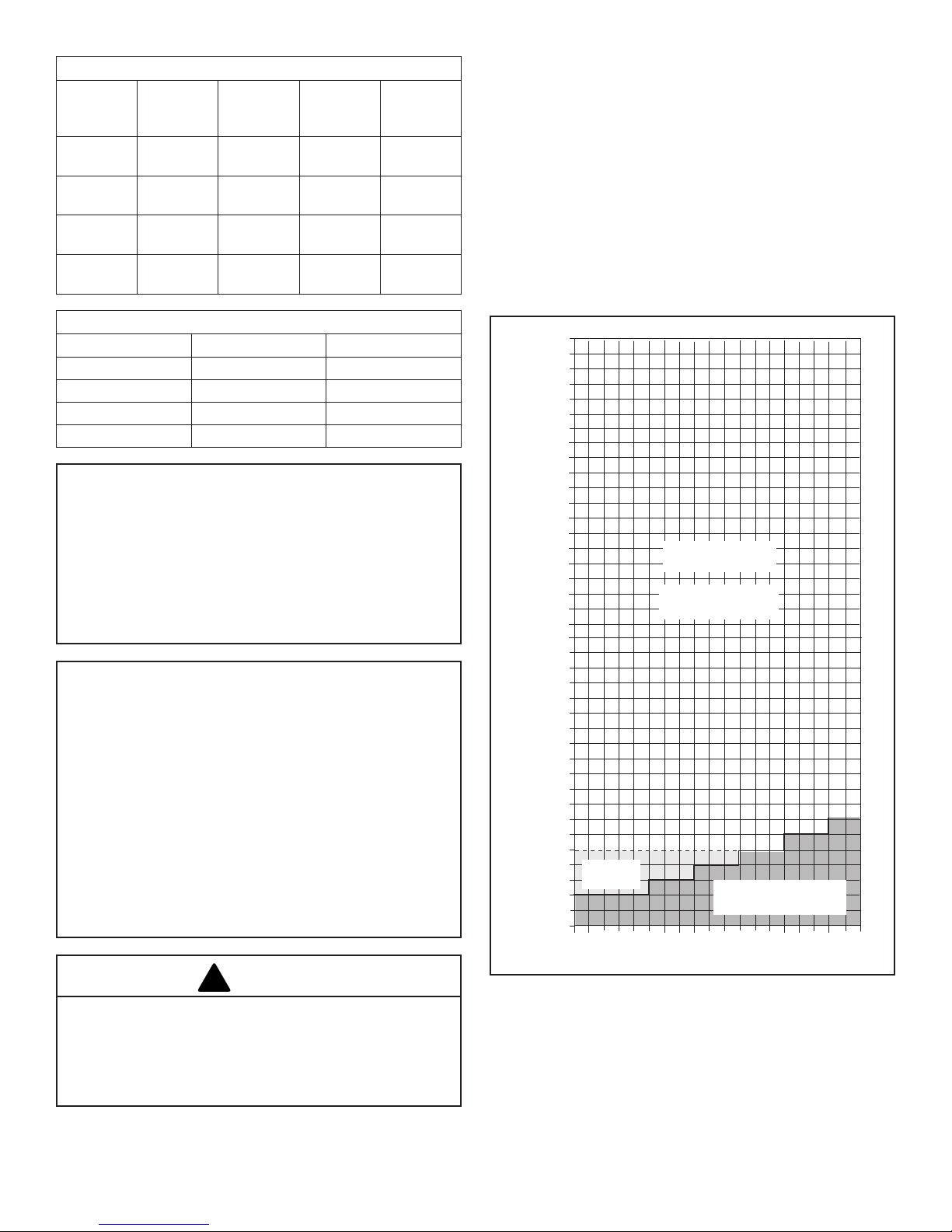
Horizontal Termination
The vent must rise vertically a minimum of 24" (610 mm) off
the top of the unit, before the rst elbow. The horizontal run
may extend up to 20’ (6m) and include a vertical rise of up to
40’ (12 m). (Figure 7) Horizontal termination must also meet
the criteria shown in Figures 10 through 12.
• Approved vent systems must terminate above and
including the heavy line in Figure 7.
• Two 45° elbows may be substituted for each single 90°
elbow.
• With a rise between 2’ – 5’, one 90° or two 45° elbows
may be used.
May use up to
three 90° Elbows
No Restrictor Plate
Required
One 90°
Elbow
Figure7-Horizontalventterminationwindow.
Unacceptable
Venting Conguration
3-90-20306760Vermont Castings • Stardance SDDVTSB Installation Manual_R10 • 04/18
Vertical Termination
20
19
18
16
15
14
13
12
11
10
9
8
7
6
5
4
3
2
1
0
20
1 2 3 4 5 6 7 8 9 10 11 12 13 14 15 16 17 18 19
Vertical Run (in feet)
(Measure from the appliance flue collar to the top of the vent pipe.)
Horizontal Run (in feet)
21
22
23
24
25
26
27
28
29
30
31
32
33
34
35
36
37
38
39
40
ST132a
FDV28
Vertical
vent run
12/3/99 djt
A vertical vent system must terminate no less than 8’ (2.44 m)
and no more than 40’ (12 m) above the appliance ue collar. A
restrictor plate (supplied) must be used, where specied, in all
vertically terminated vent systems. (Refer to Figure 8) NOTE:
The restrictor plate supplied with the vertical termination
should be discarded. Adjust the restrictor plate according to
recommendations in Figure 10. A vertically terminated vent
system must also conform to the following criteria:
• No more than three 90° elbows may be used.
• Two 45° elbows may be substituted for one 90° elbow.
No more than six 45° elbows may be used.
• Vent must rise a minimum of 2 feet (305 mm) before
offset is used.
• Termination height must conform to roof clearance as
specied in Figure 11.
All Vertical
Terminations in this
area Require use
of the Restrictor
Plate*
Restrictor Plate Adjustment for Extended Pipe Runs
The Stardance stove is shipped with a restrictor plate in
the Parts Bag. Adjustments can be made by loosening the
adjustment screw to allow the restrictor plate to slide up or
down. (Figure 9) A guide for usage is shown in Figure 10.
NOTE: Some installations may require some adjustment
by the installer for optimum ame appearance. Optimum
ame appearance is a ame that is not subject to tall, dirty
yellow ames producing soot or ames lifting off of the
ember bed ports.
Restrictor Plate Adjustment
• Remove the screw in the back wall of the rebox.
• Install restrictor plate as shown in Figure 9 with cut out
on left side. Secure with adjustment screw.
• Measure from center of screw to top edge of diverter
(Figure 9) to adjust plate according to guidelines in
Figure 10.
• Tighten attachment screw.
• Install logs following log installation instructions.
Restrictor Plate
Vertical terminations
must be within this
area
**No Restrictor Plate
Figure 8 - Vertical vent termination window.
9
**
Unacceptable
Venting Conguration
Figure9-Loosenscrewtoadjustrestrictorplate.
Examples for Extended Run/Restrictor Plate Settings
Vertical 20’
(6 m), 90°
elbow, out 8’
(2.4 m)
Vertical 11’
(3.4 m), 90°
elbow, out 2’
(610 mm)
Vertical 40’
(12 m)
Vertical 5’
(1.5 m), 90°
elbow, out 5’
Restrictor plate measurement from top of plate to
center of screw:
23⁄4” (70 mm)
from center
of screw to
top edge of
Plate down
to top of slot
Plate down
to top of slot
23⁄8” (60 mm)
from center
of screw to
top edge of
plate
Figure10
3-90-20306760Vermont Castings • Stardance SDDVTSB Installation Manual_R10 • 04/18
(1.5 m)
plate

Vent Termination Clearances
When planning the installation, consider the location of the
vent terminal and clearances. Some of the most common
clearances to keep in mind are shown in Figure 11.
Important: All vent clearances must be maintained.
Check your vent termination clearances against Figures
11 and 12.
The vent should be placed so that people cannot be burned
by accidentally touching the vent surfaces when the stove
is operating.
The vent termination should be located where it cannot be
damaged by such things as automobile doors, lawn mowers
or snowblowers and it should be located away from areas
where it could become blocked by snow, etc.
Some considerations are:
• Obstructions or impediments to venting.
• Nearby combustible materials that could come into
contact with combustion exhaust gases.
• Other nearby openings {within 12" (305 mm)} through
which exhaust gas could reenter the building.
• All vegetation within 3’ (76 mm) that may interfere with
the draft.
Other factors that inuence where the installation will be
sited include the location of outside walls, where additional
heat may be desired in the home, where the family members
gather most regularly, and perhaps most importantly, the
distance limitations of the venting system.
IMPORTANT
The horizontal termination must not be recessed into
the exterior wall or siding.
Horizontal vent runs must be level toward the vent
termination.
Clearances around the vent termination must be
maintained.
For installations using DuraVent pipe, parallel installations
with minimum wall clearance have restricted access for
connecting the Horizontal Vent Cap straps to the vent
pipe. See the maker’s instructions for recommended
installation procedures.
Your stove is approved to be vented either through the side
wall, or vertical through the roof.
• HHT does not require any opening for inspection of vent
pipe.
• Only HHT SLP components or DuraVent venting
components specically approved and labeled for this
stove may be used.
• Minimum clearances between vent pipes and
combustible materials is one (1") inch (25 mm), except
where stated otherwise.
• Venting terminals shall not be recessed into a wall or
siding.
• Horizontal venting must be installed on a level plane
without an inclining or declining slope.
There must not be any obstruction such as bushes, garden
sheds, fences, decks or utility buildings within 24" from the
front of the termination hood.
Do not locate termination hood where excessive snow or ice
build up may occur. Be sure to check vent termination area
after snow falls, and clear to prevent accidental blockage of
venting system. When using snow blowers, make sure snow
is not directed towards vent termination area.
Location of Vent Termination
It is imperative the vent termination be located observing the
minimum clearances as shown in this manual.
10
3-90-20306760Vermont Castings • Stardance SDDVTSB Installation Manual_R10 • 04/18
General Venting Information - Termination Location
V
X
X
X
D
E
B
B
B
C
B
M
B
A
J
K
F
L
VENT TERMINATION AIR SUPPLY INLET
AREA WHERE TERMINAL IS NOT PERMITTED
H
I
Fixed
Closed
Operable
Operable
Fixed
Closed
B
INSIDE
CORNER DETAIL
A
G
CFM145a
V
V
V
V
V
V
V
V
N
A = Clearance above grade, veranda, porch, deck
CANADIAN INSTALLATIONS
1
12" (30cm) 12" (30cm)
US INSTALLATIONS
2
or balcony
B = Clearance to window or door that may be
opened
C = Clearance to permanently closed window 12" (305mm) recommended to prevent window
D = Vertical clearance to ventilated soft located
6" (15cm) for appliances <10,000 BTU/h (3kW)
12" (30cm) for appliances >10,000 BTU/h (3kW)
and <100,000 BTU/h (30kW)
36" (91cm) for appliances >100,000 BTU/h (30kW)
6" (15cm) for appliances <10,000 BTU/h (3kW)
9" (23cm) for appliances >10,000 BTU/h (3kW) and
<50,000 BTU/h (15kW)
12" (30cm) for appliances >50,000 BTU/h (15kW)
12" (305mm) recommended to prevent window
condensation
condensation
18" (458mm) 18" (458mm)
above the terminal within a horizontal distance
of 2' (610 mm) from the center line of the
terminal
E = Clearance to unventilated soft 12" (305mm) 12" (305mm)
F = Clearance to outside corner see next page see next page
G = Clearance to inside corner see next page see next page
H = Clearance to each inside of center line
extended above meter/regulator assembly
3' (91cm) within a height of 15' (5m) above the
meter/regulator assembly
3' (91cm) within a height of 15' (5m) above the
meter/regulator assembly
I = Clearance to service regulator vent outlet 3' (91cm) 3' (91cm)
J = Clearance to non-mechanical air supply inlet
to building or the combustion air inlet to any
other appliance
6" (15cm) for appliances <10,000 BTU/h (3kW)
12" (30cm) for appliances >10,000 BTU/h (3kW)
and <100,000 BTU/h (30kW)
36" (91cm) for appliances >100,000 BTU/h (30kW)
6" (15cm) for appliances <10,000 BTU/h (3kW)
9" (23cm) for appliances >10,000 BTU/h (3kW) and
<50,000 BTU/h (15kW)
12" (30cm) for appliances >50,000 BTU/h (15kW)
K = Clearance to mechanical air supply inlet 6' (1.83m) 3' (91cm) above if within 10' (3m) horizontally
L = Clearance above paved sidewalk or paved
7' (2.13m)
†
7' (2.13m)
†
driveway located on public property
M = Clearance under veranda, porch, deck or
12" (30cm)
‡
12" (30cm)
‡
balcony
N = Clearance above a roof shall extend a minimum of 24” (610mm) above the highest point when it passes through the roof surface, and any other obstruction
within a horizontal distance of 18” (450mm).
Figure 11 - Vent termination clearances.
1 In accordance with the current CSA-B149 Installation
Codes
2 In accordance with the current ANSI Z223.1/NFPA 54
National Fuel Gas Codes
† A vent shall not terminate directly above a sidewalk or
paved driveway which is located between two single
family dwellings and serves both dwellings
‡ Only permitted if veranda, porch, deck or balcony is fully
open on a minimum 2 sides beneath the oor.
11
NOTE:
1. Local codes or regulations may require different
2. The special venting system used on Direct Vent Fireplaces
3. HHT assumes no responsibility for the improper
clearances.
are certied as part of the appliance, with clearances
tested and approved by the listing agency.
performance of the appliance when the venting system
does not meet these requirements.
3-90-20306760Vermont Castings • Stardance SDDVTSB Installation Manual_R10 • 04/18
Termination Clearances
Termination clearances for buildings with combustible and noncombustible exteriors.
Inside Corner
Outside Corner
F =
G =
G
Combustible
6" (152 mm)
Noncombustible
V
2" (51 mm)
V
F
Combustible
6" (152 mm)
Noncombustible
2" (51 mm)
Alcove Applications*
C
D
C
V
O
E
Balcony -
with no side wall
Balcony -
with perpendicular side wall
E = Min. 2” (51 mm) for
non-vinyl sidewalls
Min. 12” (305 mm) for
vinyl sidewalls
O = 8’ (2.4 m) Min.
M
V
M =
Combustible &
Noncombustible
12" (305 mm)
*NOTE: Termination in an alcove space (spaces open only on one side and with an overhang) is permitted with the dimensions specied for vinyl or
non-vinyl siding and softs. 1. There must be a 3’ (914 mm) minimum between termination caps. 2. All mechanical air intakes within 10’ (1 m) of a
termination cap must be a minimum of 3’ (914 mm) below the termination cap. 3. All gravity air intakes within 3’ (914 mm) of a termination cap must
be a minimum of 1’ (305 mm) below the termination cap.
Combustible &
Noncombustible
M = 12" (305 mm)
P = 6” (152 mm)
M
# of
V
P
Caps
1 3’ (914 mm) 2 X D
2 6’ (1.8 m) 1 X D
3 9’ (2.7 m) 2/3 X D
4 12’ (3.7 m) 1/2 X D
D
= # of Termination caps x 3
Min.
C
= (2 / # termination caps) x D
Max.
D
Min.
C
Max.
Actual
Actual
Actual
Actual
Actual
Figure 12 - Termination clearances.
12
3-90-20306760Vermont Castings • Stardance SDDVTSB Installation Manual_R10 • 04/18
Approved Vent System Components
The Stardance heater must be vented to the outdoors through
an adjacent exterior wall or through the roof. The venting
system must be comprised of the appropriate listed venting
components specied on this page. These parts are available
from DuraVent Corporation or your Vermont Castings Dealer.
See Figure 4 for dimensions relevant to the standard
minimum-vent kits.
HHT Components*
SLP Horizontal Termination Kit (Termination
Cap, SLP24-BK, SLP6-BK, SLP6A-BK,
SLP90-BK, SLP-WT-BK & CCSLP)
Stove Adapter Kit (Includes 30' of 4" Flex,
adapters, wall thimble, masonry and ZC
ashing, 991DA Cap and Fasteners
Trapezoid Termination Kit (3-1/8” - 4-3/4”) SLP-TRAP1
Trapezoid Termination Kit (5-1/4” - 9-1/4”) SLP-TRAP2
Rear Vent Termination Kit SLP-RVTK
Vertical Termination cap - High Wind
(includes storm collar)
Decorative Wall Thimble Cover SLP-WT-BK
Decorative ceiling restop - black SLP-DCF-BK
Cathedral ceiling support - black SLP-CCS-BK
4" (100mm) pipe length - black SLP4-BK
6" (150mm) pipe length - black SLP6-BK
12" Pipe length-black SLP12-BK
24" Pipe length-black SLP24-BK
36" (915mm) pipe length - black SLP36-BK
48" Pipe length-black SLP48-BK
3" - 6" (75 - 150mm) telescoping pipe
extension - black
3" - 12" telescoping pipe extension-black SLP12A-BK
45 degree elbow-black SLP45-BK
90 degree elbow-black SLP90-BK
Radiance, Stardance, Oxford SLP adapter CCSLP
Freestanding Draft Hood Adapter FSDHAGSLP
SL Snorkel Cap (Includes 1 pair of restops) SLK-SNKD
*CCSLP adapter is required when using HHT components.
SLP-SK-BK
LINK-STOVE
SLP-TVHW
SLP6A-BK
DuraVent Components
Minimum Horizontal Vent Kit 2792
Starter Pipe Assembly (incl. inner & outer
sections)
90° Elbow, Blk. 46DVA-E90B*
45° Elbow, Gal. 46DVA-E45
6" Straight, Blk. 46DVA-06B*
9" Straight, Blk. 46DVA-09B
11" – 145⁄8" Adjustable Straight Section 46DVA-08AB
12" Straight 46DVA-12
24" Straight 46DVA-24B*
36" Straight 46DVA-36B
48" Straight 46DVA-48
Horizontal Vent Cap 46DVA-HC*
Wall Plate 46DVA-DC
Vinyl Siding Shield 46DVA-VSS
Snorkel Termination – 14" 46DVA-SNK14
Snorkel Termination – 36" 46DVA-SNK30
Wall Strap 46DVA-WS
Cathedral Ceiling Support Box 46DVA-CS
Storm Collar 46DVA-SC
Firestop Spacer 46DVA-FS
Flashing 0/12 - 6/12 46DVA-F6
Flashing 6/12 - 12/12 46DVA-F12
Wall Thimble 46DVA-WT
Wall Thimble 46DVA-WT
Wall Thimble Cover (Brass) 3PVP-TKV
Wall Firestop 46DVA-WFS
Attic Insulation Shield 46DVA-IS
Co-Linear Vent Adapter 46DVA-GCL
Wall Thimble Cover (Brass) 3PVP-TKV
Wall Firestop 46DVA-WFS
Attic Installation Shield 46DVA-IS
Co-Linear Vent Adapter 46DVA-GCL
Steel Chimney Conv. Kit A (6-5/8" - 8-5/8") 46DVA-KCA
Steel Chimney Conv. Kit B (6-5/8" - 10-1/2") 46DVA-KCB
Steel Chimney Conv. Kit C (6-5/8" – 13") 46DVA-KCC
Masonry Chimney Conversion Kit 46DVA-KMC
Vertical Termination Cap (High Wind) 46DVA-VCH
Vertical Termination Cap (Low Prole) 46DVA-VC
*Included in Minimum Horizontal Vent Kit #2792
All DuraVent Straight vent pipe sections have a net length 1-1/2"
(37mm) less than the nominal dimension; i.e., a 6" (152 mm)
Straight pipe section has an effective length of 4-1/2" (115 mm).
2768*
13
3-90-20306760Vermont Castings • Stardance SDDVTSB Installation Manual_R10 • 04/18
Assembly & Installation
!
Tools Required
• Phillips screwdriver (stub)
• Utility knife
• Metal drill bit: size 28 (.140"/3.5mm)
• Flat-blade screwdriver
• Power drill
• Reciprocating saw
• 9/16" Wrench
• 1/2" Wrench
Parts Bag Contents:
• LP Conversion Kit
• Three (3) Vent Screws
• Two (2) Switch bracket screws
• Wood handle w/insert lifter (handle for operable door)
• Restrictor Plate
• 4" Starter pipe
• On-Off switch, housing, and wiring harness
• Three (3) Phillips round-head bolts, 1/4" – 20 x 1/2"
• One (1) Tube of Vent Gasket Cement
• Homeowner’s Installation and Operating Manual
Unpack Stove
Using the 1/2" wrench remove the (4) lag bolts installed
through the shipping brackets and into the skid. Once the lag
bolts are removed, remove the shipping brackets from around
each leg leveller located at each leg with the 9/16" Wrench.
Snapstat
Bracket
Snapstat/
Extension
Not Used On
Stardance
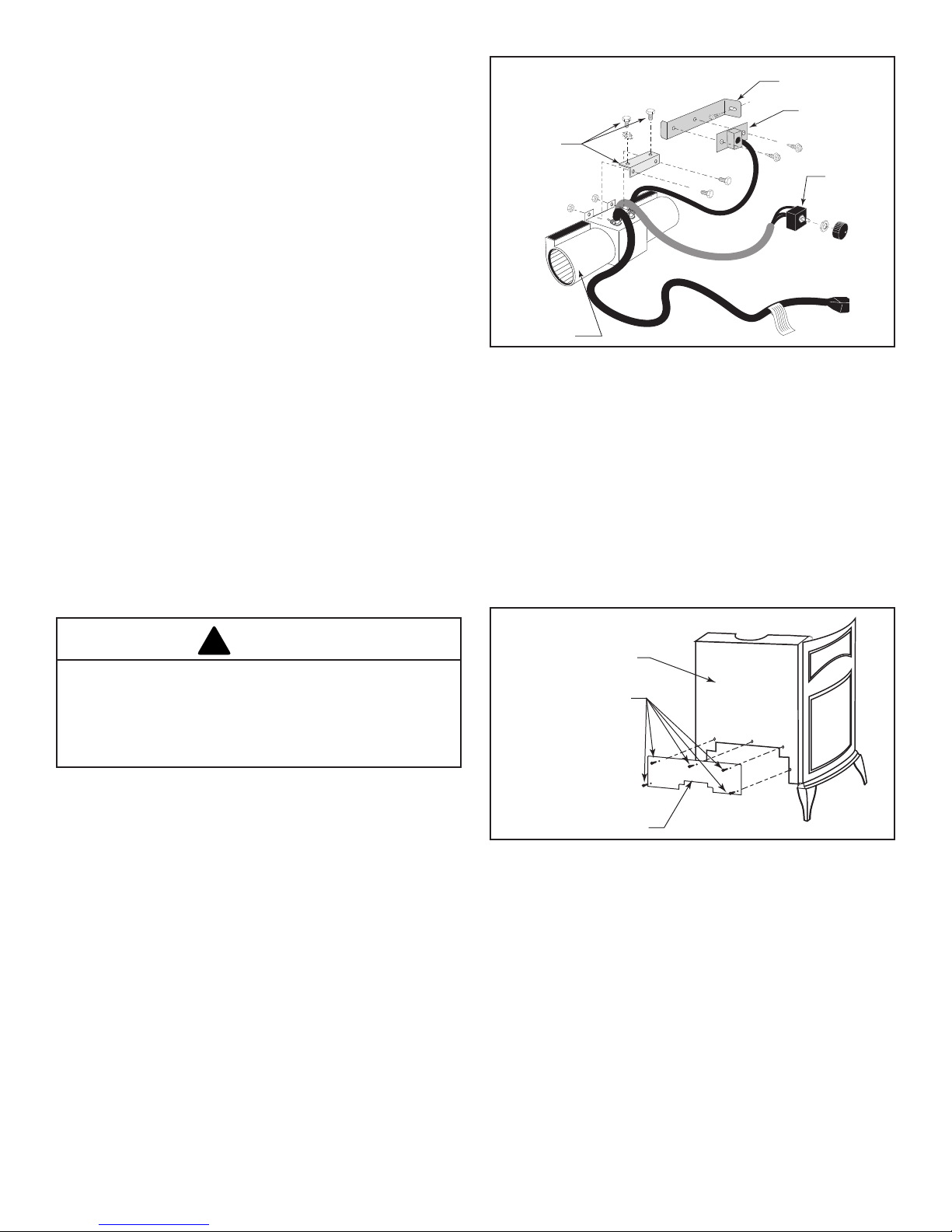
Blower
Assembly
Figure 15 - Fan kit components.
Assembly
Rheostat
Assembly
2. Remove the rear skirt insert panel at the bottom of the
Rear Skirt (Figure 16) and fasten the blower assembly
to the rebox back with the two Phillips pan-head bolts
originally installed in the rebox back. (‘1’, Figure 17)
3. Attach the snapstat assembly to the snapstat bracket
with two sheet-metal screws. (‘2’, Figure 17) Attach
the snapstat bracket to the stove with a hex-head bolt
passing through the bracket and into the stove base. (‘3’,
Figure 17)
4. The rheostat control switch attaches to the left side of the
valve bracket at the front of the stove. (Figure 18)
WARNING
This appliance is equipped with a three-prong (grounded)
plug for your protection against shock hazard and should
be plugged directly into a properly grounded three-prong
receptacle. Do not cut or remove the grounding prong
from this plug.
Install the Optional Fan – SDDVT models (Millivolt Only See page 27 for SC Models)
If you are installing the optional convection Fan Kit #2767
(FK26), continue here. It is easiest to install fan kit before
connecting gas line.
1. The fan kit includes a Blower Assembly and a Rheostat
Assembly, connected by a cable. (Figure 15) The Blower
Assembly mounts to the bottom rear of the stove, and the
Rheostat mounts to the valve cover plate. The assembly
includes a ‘snapstat’ which automatically turns the fan
On (or Off) above (or below) approximately 109°. The
Rheostat also provides a range of fan speed settings
from Off (which overrides the snapstat function) to High.
Unpack and inspect the Blower assembly. Conrm that
the fan spins freely.
Rear Skirt
Sheet Metal Screws
Rear Skirt Insert
Figure 16 - Remove rear shroud.
14
3-90-20306760Vermont Castings • Stardance SDDVTSB Installation Manual_R10 • 04/18
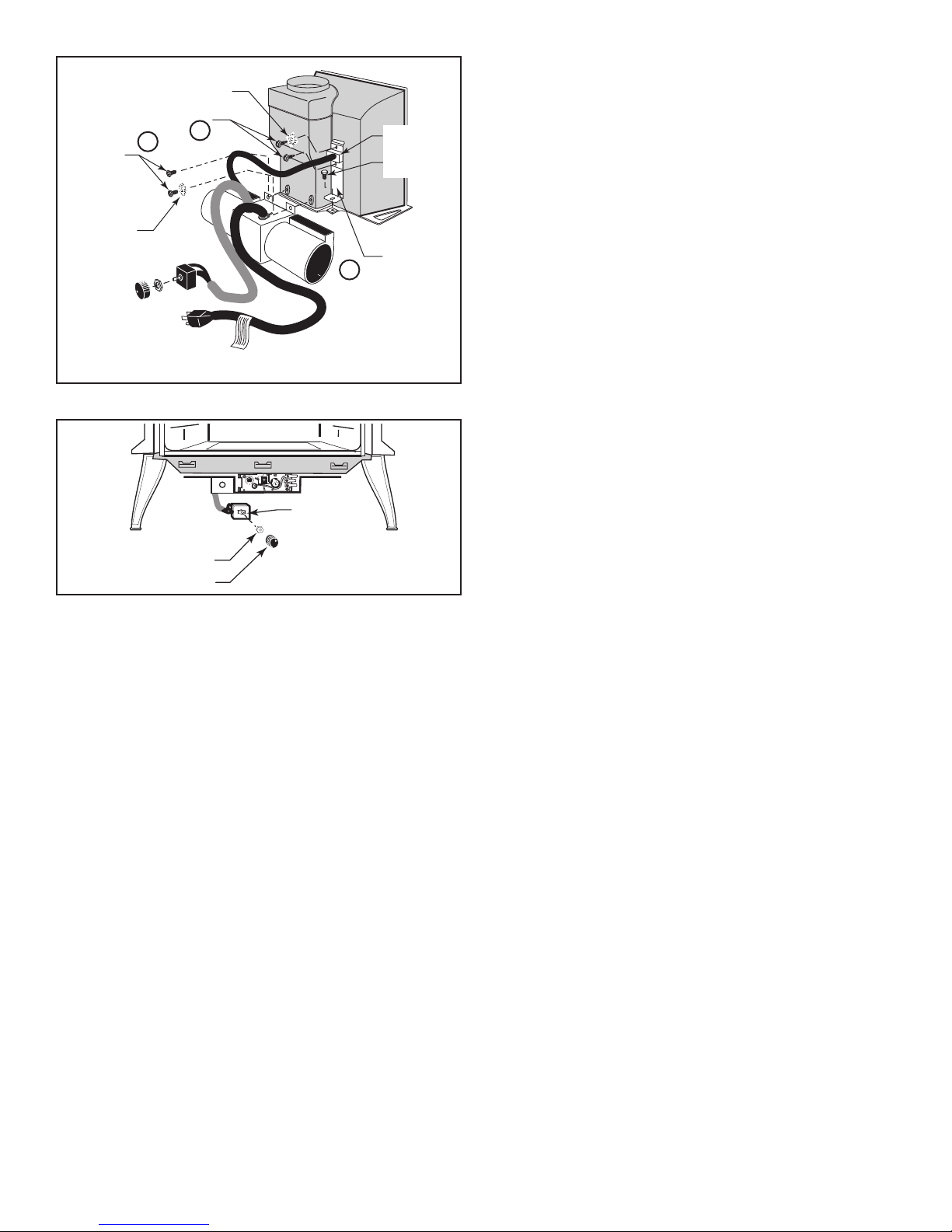
Star Washer
Sheet Metal Screws
Phillips
Pan Head
Bolts
Star
Washer
NOTE: Shown without shell for clarication
1
2
3
Figure17-Attachblowerassemblyandsnapstat.
Rheostat
Snapstat
1/4” – 20
Hex Bolt
Snapstat
Bracket
Rheostat
Retaining Collar
Rheostat Knob
Figure 18 - Attach the fan rheostat.
• Remove retaining nut from shaft of rheostat. (if
preinstalled)
• Insert the rheostat through the hole in the back of the left
side of the valve bracket, aligning the locator pin with the
smaller hole in that bracket.
• Thread the retaining nut onto the shaft of the rheostat,
tightening with a wrench. Do not over tighten.
• Attach the control knob to the rheostat shaft.
• Use the wire tie to secure the fan and rheostat wire
harnesses together.
15
3-90-20306760Vermont Castings • Stardance SDDVTSB Installation Manual_R10 • 04/18
Venting System Assembly
!
!
!
!
Outside Wall
Finishing Material
(Vinyl Siding, etc.)
CAUTION
All HHT Direct Vent Stoves have been tested and
approved to ANSI/CSA Standards and will operate safely
when installed in accordance with this instruction manual.
Read all instructions before starting installation, then follow
these instructions carefully to maximize stove performance
and safety. Report damaged parts to your dealer.
WARNING
Always maintain minimum clearances around vent
systems. Rear/Top Vent Vertical Side wall: Horizontal
sections of this vent system require a minimum of 3” (76
mm) clearances to combustibles at the top of the ue and
1” (25 mm) clearance at the sides and bottom until the ue
penetrates the outside wall. A minimum 1” clearance all
around the ue is acceptable at this point of penetration. If
vertical rise is 71⁄2 feet (2.3 m) or higher when top venting,
the clearance to combustibles is 1” on all sides of the
horizontal run. FOR VERTICAL RUNS ONLY, maintain a
1” (25 mm) minimum clearance to all sides. Do not pack
the open air spaces around the stove or ue with insulation
or other materials. Any horizontal run must have a 1/4” rise
for every one (1) foot of run towards the vent termination.
Never run the vent level or down.
• These models are approved to use HHT direct vent pipe
components and HHT termination kits, and DuraVent
components. No other venting system components may
be used.
• Horizontal runs must be supported every 3 feet (914 mm)
using wall straps. Vertical runs must be supported every
8 feet (2.4 m) using wall straps. Slip wall straps loosely
on to pipe. Attach straps to framing members using nails
or screws. Tighten nut/bolt to secure pipe.
• The stove and venting system should be inspected
before initial use and at least annually by a qualied
eld service person. Inspect the external vent cap on a
regular basis to make sure that no debris is interfering
with the airow. Inspect entire venting system to ensure
proper function.
Failure to follow these instructions may create a possible
re hazard and will void the warranty.
Any common venting of this gas appliance with other gas
appliances is not allowed.
Important Safety Information
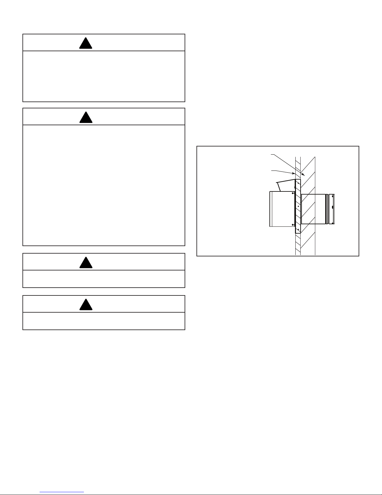
The termination cap MUST be vented directly to the outside.
The termination kit MUST NEVER be connected to a chimney
ue(s) servicing a separate solid-fuel burning appliance or
any other appliances.
• Termination cap MUST NOT be recessed into a wall (see
Figure 19).
• The installation must conform with local codes or in the
absence of local codes, with the National Fuel Gas Code,
ANSI Z223.1 (in the United States) or with the current
installation code CSA B149 (in Canada).
WARNING
WARNING
Figure19-Terminationcaponwall
Before You Start
Plan your installation. Set the stove in place and survey how
to best vent the unit. Select the appropriate termination kit
and vent pipe for the installation. Read these instructions and
the stove Homeowner’s Manual before beginning installation.
After vent conguration has been decided, begin attaching
pipe to unit.
Items required for installation:
Tools:
Phillips screwdriver Hammer
Saw and/or saber saw Level
Measuring Tape Electric drill and bits
Pliers Square
Building Supplies:
Framing materials
Wall nishing materials
Caulking Material (noncombustible)
16
3-90-20306760Vermont Castings • Stardance SDDVTSB Installation Manual_R10 • 04/18
WARNING
!
!
!
CEMENT
Refer to pages 8 and 9 of this manual for the minimum
and maximum venting requirements of your stove and
for approved horizontal vent termination locations prior
to installation. Failure to do so may cause re hazard.
WARNING
Any horizontal run must have a 1/4” rise for every one (1)
foot of run towards the vent termination. Never allow the
vent pipe to run down. This could cause high temperatures
and may present a re hazard.
WARNING
Termination cap must be positioned so the embossed
arrow is pointed up.
General Information
The Stardance is approved for installation only with the
vent components listed in the "Approved Vent System
Components" section in this manual. Follow the vent
component instructions exactly.
For U.S. installations: The venting system must conform with
local codes and/or the current National Fuel Gas Code, ANSI
Z223.1/NFPA 54.
For Canadian installations: The venting system must conform
to the current CSA B149.1 installation code.
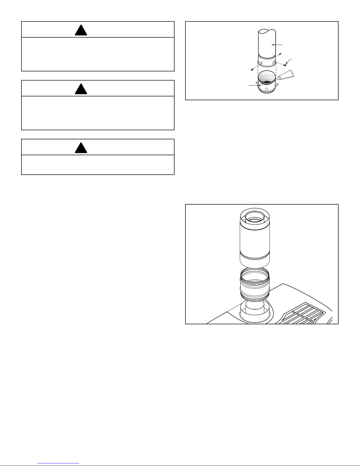
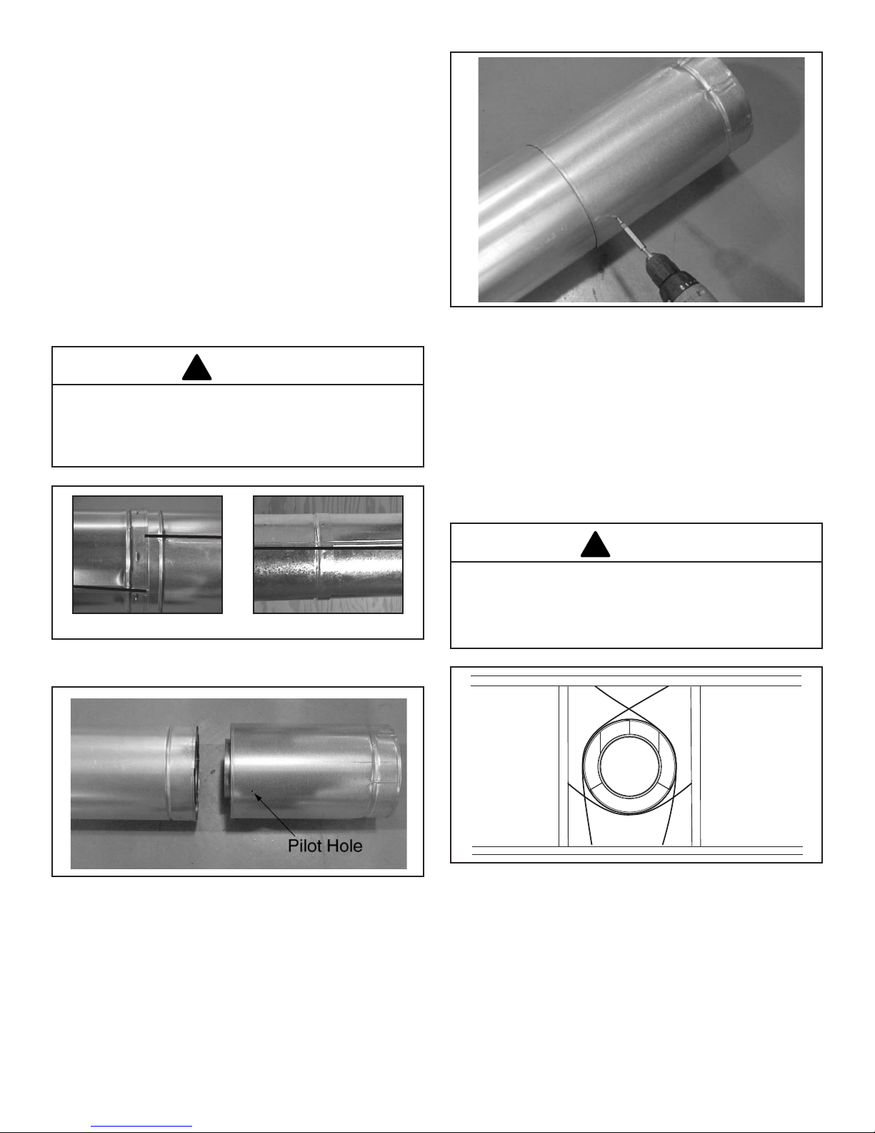
Install the Vent Adapter Pipe (HHT SLP Vent
Components)
1. Attach Inner Starter Pipe, (found in the Parts Bag), to the
next section of inner pipe.
2. Run a bead of sealant about 1/2" from the upper end of
the Inner starter pipe and join the two sections together.
3. Drill three pilot holes into the Inner Starter and secure
the assembly with three sheet metal screws. (Figure 20)
4. Dry t the Inner Pipe assembly to the stove for the
purpose of determining the center line of the pipe on the
wall.
5. Side Wall Terminations: Dry t the outer elbow with the
vertical outer vent and conrm the centerline alignment
with the wall thimble opening.
Figure20-Connecttheinnerstarterwiththenextsectionof
inner vent pipe.
1. Attach the Inner Vent Assembly to the stove.
2. Place a 3/8" bead of millpack caulk around the inside of
the cast starter collar. Insert the 6-5/8" outer adapter into
the cast outer starting collar and press down rmly.
3. Install the CCSLP Outer Adapter Pipe.
4. Place a 3/8" bead of millpack caulk around the 4"
crimped end of the starter collar on the stove. Attach the
SLP pipe to the adapter, and secure by aligning adapter
and pipe seams, pressing down rmly until pipe stops,
and twisting to lock into place. (Figure 21)
Figure21-Attachinnerassemblytouecollar.
17
3-90-20306760Vermont Castings • Stardance SDDVTSB Installation Manual_R10 • 04/18
Assemble Slip Sections
!
!
The outer ue of the slip section should slide over the outer
ue of the pipe section and into (inner ue) the last pipe
section. (Figure 23)
Slide together to the desired length, making sure that a 1-1/2"
outer ue overlap is maintained between the pipe section
and slip section.
The pipe and slip section need to be secured by driving two
1/2 in. screws through the overlapping portions of the outer
ues using the pilot holes. (Figure 24)
This will secure the slip section to the desired length and
prevent it from separating. The slip section can then be
attached to the next pipe section.
If the slip section is too long, the inner and outer ues of the
slip section can be cut to the desired length.
WARNING
Risk of Fire/Explosion! DO NOT break seals on slip sec-
tions. Use care when removing termination cap from slip
pipe. If slip section seals are broken during removal of the
termination cap, vent may leak.
Figure24-ScrewsintoSlipSection
Secure the Vent Sections
Vertical sections of SLP pipe must be supported every 8 ft.
The SLP restop includes tabs that may be used to secure
vertical sections.
The vent support or plumber’s strap (spaced 120° apart)
may be used to secure the vertical sections of pipe (see
Figure 25).
Horizontal sections of vent must be supported every 5 ft with
a vent support or plumber’s strap (see Figure 26).
INCORRECTCORRECT
Figure 22 - Make sure the seams are not aligned to prevent
unintentional disconnection.
Figure23-SlipSectionPilotHoles
WARNING
Risk of Fire/Explosion/Asphyxiation! Improper support
may allow vent to sag and separate. Use vent run supports
and connect vent sections per installation instructions. DO
NOT allow vent to sag below connection point to appliance.
Figure 25 - Securing Vertical Pipe Sections
18
3-90-20306760Vermont Castings • Stardance SDDVTSB Installation Manual_R10 • 04/18
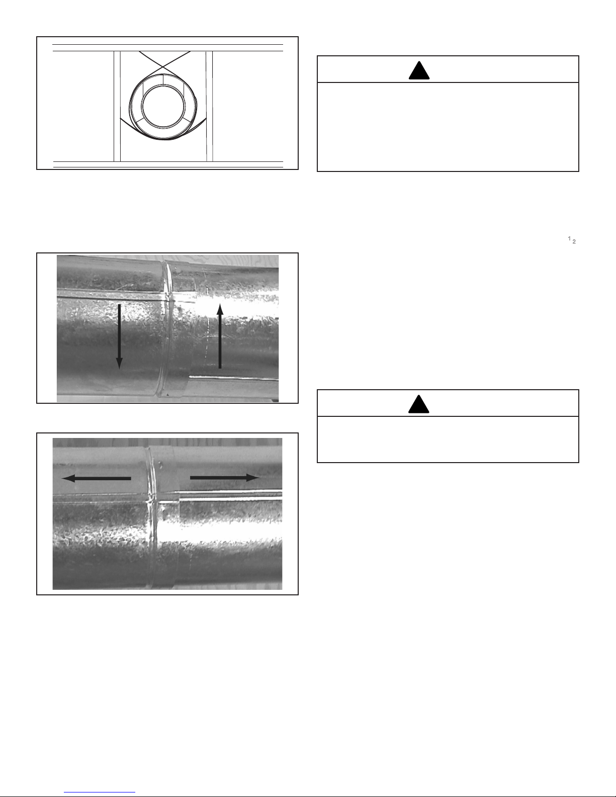
Figure 26 - Securing Horizontal Pipe Sections
!
!
Disassemble Vent Sections
To disassemble any two pieces of pipe, rotate either section
(Figure 27), so that the seams on both pipe sections are
aligned (Figure 28). They can then be carefully pulled apart.
Horizontal Termination Cap
WARNING
Risk of Fire! The telescoping ue section of the termination
cap MUST be used when connecting vent.
• 1-1/2” (38 mm) minimum overlap of vent and
telescoping ue section is required.
Failure to maintain overlap may cause overheating and
re.
Note: For horizontal vent runs through a combustible
wall and framing dimensions, refer to appliance
installation manual.
Install the Horizontal Termination Cap
Attach slip section of cap to last vent section. Maintain 11⁄2"
overlap between slip and vent sections.
Note: For installations using black pipe, slide the
decorative wall thimble over the last vent pipe before
connecting the termination to the pipe. When this
connection has been made, slide the wall thimble up to
the interior wall surface and attach with screws provided.
Secure termination cap to exterior wall using provided holes
and fasteners.
Vent termination must not be recessed in the wall. Siding
may be brought to the edge of the cap base.
Figure27-RotateSeamsforDisassembly
Figure 28 - Align and Disassemble Vent Sections
CAUTION
Risk of Burns! Local codes may require installation of a
termination guard to prevent anything or anyone from
touching the hot cap.
Flash and seal as appropriate for siding material at outside
edges of cap.
When installing a horizontal termination cap, follow the cap
location guidelines as prescribed by current ANSI Z223.1
and CAN/CGA-B149 installation codes.
19
3-90-20306760Vermont Castings • Stardance SDDVTSB Installation Manual_R10 • 04/18
Divert Roof Run-off
Install L-shaped
HHT recommends, where excessive water run-off is possible,
use of one of the two options shown in Figure 29 to prevent
water running off the roof and onto/into the horizontal
termination cap.
Vent Opening for Combustible Walls
9"
(244 mm)
9"
(244 mm)
Stove Hearth Framing Detail
Opening for Noncombustible Wall
Install gutter
diverter
Figure29-LocateVentOpeningonWall
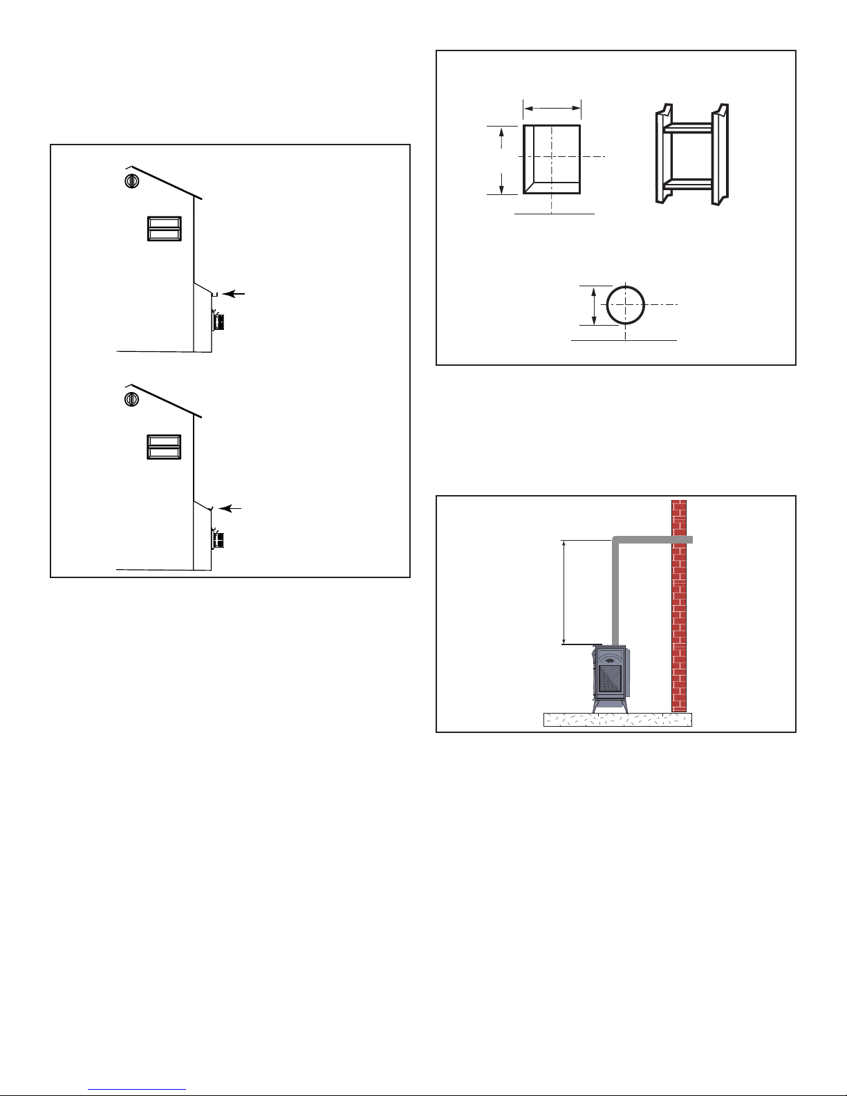
Vertical Side Wall Installation:
NOTE: For all top vent vertical through-the-roof
installations, install the supplied ue restrictors onto
the top edge of the rebox ue adapter according to
the Vertical Side wall Installation Flue Restrictor Chart.
1. Locate vent opening on the wall. It may be necessary
to rst position the stove and measure to obtain hole
location. Depending on whether the wall is combustible
or noncombustible, cut opening to size. Figure
30 (For combustible walls rst frame in opening.)
Combustible Walls: Cut a 9"H x 9"W (244 x 244 mm) hole
through the exterior wall and frame as shown. Figure 30
Noncombustible Walls: Hole opening must be 7" (178
mm) in diameter.
NOTE:Whenusingexvent,theopeningwillhaveto
bemeasuredaccordingtothe1/2”(13mm)risein12”
(305mm)ventrun.
7"
(190 mm)
Stove Hearth
Figure30-LocateVentOpeningonWall
2. Secure restop to the inside frame, center in the 9" x 9"
vent opening.
3. Place stove into position. Measure the vertical height (X)
required from the base of the ue collars to the center of
the wall opening. Figure 31
X
Figure31-VerticalHeightRequirements
4. Using appropriate length of pipe section(s) attach to
stove by twisting collar.
5. Measure the horizontal length requirement including a 2”
(51 mm) overlap, i.e. from the elbow to the outside wall
face plus 2” (51 mm) (or the distance required if installing
a second 90° elbow). Figure 32
NOTE: Always install vertical side wall horizontal venting
witha1/4”riseforevery12”ofrun.
20
3-90-20306760Vermont Castings • Stardance SDDVTSB Installation Manual_R10 • 04/18
 Loading...