

Vermont Castings RNVOD 3346, RNVOD 3345, RNVOD 3341, RNVOD 3233, RNVOD 3234 Homeowner's Installation And Operating Manual
...
INSTALLER / CONSUMER
CER TIFI ED
D
E
S
I
G
N
C
E
R
T
I
F
I
E
D
SAFETY INFORMATION
PLEASE READ THIS MANUAL
BEFORE INSTALLING AND
USING APPLIANCE.
WARNING!
IF THE INFORMATION IN THIS
MANUAL IS NOT FOLLOWED
EXACTLY, A FIRE OR EXPLOSION
MAY RESULT CAUSING
PROPERTY DAMAGE,
PERSONAL INJURY OR LOSS OF
LIFE.
— Do not store or use gasoline
or other flammable vapors and
liquids in the vicinity of this or
any other appliance.
— WHAT TO DO IF YOU SMELL
GAS:
• Do not try to light any appliance.
• Do not touch any electric switch; do
not use any phone in your building.
• Immediately call your gas supplier
from your neighbor’s phone. Follow
the gas supplier’s instructions.
• If you cannot reach your gas sup-
plier, call the fire department.
Installation and service must be performed by a qualified installer, service
agency or the gas supplier.
Radiance Natural Vent
Gas Heater
Model RNVOD: 3233 thru 3236,
3340 thru 3349, 3355, 3356
Homeowner’s Installation
and Operating Manual
This appliance may be installed in
an after market permanently located
manufactured (mobile) home where not
prohibited by local codes.
This appliance is only for use with the
type of gas indicated on the rating plate.
This appliance is not convertible for use
with other gases unless a certified kit is
used.
INSTALLER: Leave this manual with the appliance.
CONSUMER: Retain this manual for future reference.
20004409 4/07 Rev. 17

Radiance Natural Vent Gas Heater
Table of Contents
PLEASE READ THE INSTALLATION & OPERATING INSTRUCTIONS BEFORE USING APPLIANCE.
Thank you and congratulations on your purchase of a Vermont Castings stove.
IMPORTANT: Read all instructions and warnings carefully before starting installation. Failure to follow these
instructions may result in a possible fire hazard and will void the warranty.
Installation & Operating Instructions ..........................................................................................3
Stove Dimensions ...............................................................................................................4
Clearance Requirements .....................................................................................................4
Parallel Installation ..............................................................................................................4
Corner Installation ...............................................................................................................5
Ceiling Clearances ..............................................................................................................5
Alcove Minimum Dimensions ..............................................................................................5
Mantel Clearances ..............................................................................................................5
Hearth Requirements ..........................................................................................................5
Gas Specifications ...............................................................................................................6
Gas Inlet and Manifold Pressures .......................................................................................6
High Elevations ...................................................................................................................6
Venting Requirements ......................................................................................................... 6
Vent Layout and Height Requirements ................................................................................7
Passing Through a Combustible Wall or Ceiling ................................................................. 7
Assembly Procedures
Tools Required ....................................................................................................................8
Parts Bag Contents .............................................................................................................8
Unpack and Assembly Legs ................................................................................................ 8
Install Optional Fan .............................................................................................................8
Venting System Assembly .................................................................................................12
Connect Gas Supply Line ..................................................................................................13
Burner Information .............................................................................................................13
Install ON/OFF Switch ....................................................................................................... 13
Thermostat Connection (Optional) ....................................................................................14
Install the Mesh and Grille ................................................................................................. 14
Install Rear Bracket and Log Set .......................................................................................14
Operation
Operable Doors ................................................................................................................. 16
Your First Fire ....................................................................................................................16
Pilot and Burner Information ..............................................................................................16
Flame & Temperature Adjustment ..................................................................................... 16
Flame Characteristics ........................................................................................................16
Lighting and Operating Instructions ...................................................................................16
Troubleshooting - Honeywell #8420 Gas Control System .................................................16
Fuel Conversion Instructions ............................................................................................. 19
Maintenance
Annual System Inspection ................................................................................................. 22
Logset and Burner/Cleaning and Inspection .....................................................................22
Care of Cast Iron ............................................................................................................... 22
Cleaning the Glass ............................................................................................................ 22
Glass Replacement ........................................................................................................... 22
Gasket Replacement ......................................................................................................... 23
Inspect the Vent System Annually .....................................................................................23
Check the Gas Flame Regularly .......................................................................................23
Wiring Diagrams ................................................................................................................ 24
Replacement Parts ......................................................................................................................25
Optional Accessories
Warranty ....................................................................................................................................... 30
Energuide .......................................................................................................................................32
2
..................................................................................................................28
20004409

Installation & Operating Instructions
The Radiance Direct Natural Vent Room Heater, Model Nos.
3233 thru 3236, 3340 thru 3349, 3355 and 3356 are vented
gas appliances listed to the ANSI standard Z21.88-2005 and
CSA-2.33-2005 for Vented Room Heaters, and CSA 2.17-M91,
Gas-Fired Appliances For Use at High Altitudes.
The installation of the Radiance Natural Vent Room Heater
must conform with local codes, or in the absence of local codes,
with National Fuel Gas Code, ANSI Z223.1/NFPA 54 — latest
edition and CSA B-149.1 Installation Code. (EXCEPTION: Do
not derate this appliance for altitude. Maintain the manifold
pressure at 3.5 inches w.c. for Natural Gas and 10 inches w.c.
for LP gas at maximum input.)
This appliance is only for use with the type of gas indicated on
the rating plate. This appliance is not convertible for use with
other gases unless a certified kit is used.
Installation and replacement of gas piping, gas utilization
equipment or accessories, and repair and servicing of
equipment shall be performed only by a qualified agency,
preferably NFI or WETT (Canada) certified. The term “quali
fied agency” means any individual, firm, corporation, or
company that either in person or through a representative
is engaged in and is responsible for (a) installation or
replacement of gas piping, or (b), the connection, installa
tion, repair, or servicing of equipment, who is experienced
in such work, familiar with all precautions required, and
has complied with all the requirements of the authority
having jurisdiction.
The Radiance Natural Vent Room Heater should be inspected before use and at least annually by a qualified
service agency. It is imperative that control compartments,
burners, and circulating air passageways of the appliance
be kept clean.
The Radiance Natural Vent Room Heater and its individual
shut-off valve must be disconnected from the gas supply piping
during any pressure testing of that system at test pressures in
excess of 1/2 psig (3.5 kPa).
The Radiance Natural Vent Room Heater must be isolated from
the gas supply piping system by closing its individual manual
shutoff valve during any pressure testing of the gas supply pip
ing system at test pressures equal to or less than 1/2 psig.
An accessible tap is located above the pilot/On-Off knob for
checking the inlet pressure.
This appliance mmust be properly connected to a listed 4”
(102 mm) Type B venting system or toan approved masonry
or factory-built chimney system. In Canada, a complete reline
of Class A chimneys is required. This heater is equipped with
a vent safety shutoff system.
This appliance is approved for bedroom installations in the
U.S. and Canada. Check local codes for natural vent require
ments.
This appliance may be installed in an aftermarket* manufac
tured (mobile) home, where not prohibited by state or local
codes.
Radiance Natural Vent Gas Heater
WARNING: Operation of this heater when not connected
to a properly installed and maintained venting system can
result in carbon monoxide (CO) poisoning and possible
death.
The Radiance Natural Vent Room Heater, when installed, must
be electrically grounded in accordance with local codes or, in
the absence of local codes, with the National Electrical Code
ANSI/NFPA 70, (latest edition), or of the current Canadian
Electrical Code C22.1.
Due to high temperatures this appliance should be located
out of traffic and away from furniture and draperies.
WARNING: This appliance is hot while in operation. Keep
children, clothing, and furniture away. Contact may cause
burns or ignition of combustible materials.
Children and adults should be alerted to the hazards
of high surface temperatures and should stay away to
avoid burns or clothing ignition. Young children should
be carefully supervised when they are in the same room
-
as the appliance.
Clothing or other flammable materials should not be placed
on or near the appliance.
Any safety screen, glass or guard removed for servicing
an appliance must be replaced prior to operating the ap
pliance.
The appliance area must be kept clear and free from com-
bustible materials, gasoline, and other flammable vapors
and liquids.
The flow of combustion and ventilation air must not be
obstructed. The installation must include adequate accessi
bility and clearance for servicing and proper operation.
WARNING: Do not operate the Room Heater with the
glass panel removed, cracked or broken. Replacement
of the panel should be done by a licensed or qualified
service person.
Do not use this appliance if any part has been under water.
Immediately call a qualified service technician to inspect
the appliance and to replace any part of the control system
and any gas control which has been under water.
-
Do not burn wood, trash or any other material for which this
appliance was not designed. This appliance is designed
to burn either natural gas or propane only.
This gas appliance must not be connected to a chimney
flue serving a separate solid-fuel burning appliance.
CAUTION: Label all wires prior to disconnection when
servicing controls. Wiring errors can cause improper and
dangerous operation.
Verify proper operation after servicing.
-
* Aftermarket: Completion of sale, nor for purpose of resale,
from the manufacturer.
-
Proposition 65 Warning: Fuels used in gas, woodburning or
oil fired appliances, and the products of combustion of such
fuels, contain chemicals known to the State of California to
cause cancer, birth defects and other reproductive harm.
California Health & Safety Code Sec. 25249.6
-
-
20004409
3
Radiance Natural Vent Gas Heater
R AD I A NC E
29"
(756 mm)
31"
(787 mm)
14
"
(378 mm)
4" Inner Dia.
(102 mm)
4"
(114 mm)
C
L
28"
(711 mm)
5"
(127 mm)
9"
(241 mm)
18"
(464 mm)
Supply
Inlet
C
L
C
L
C
D
B
A
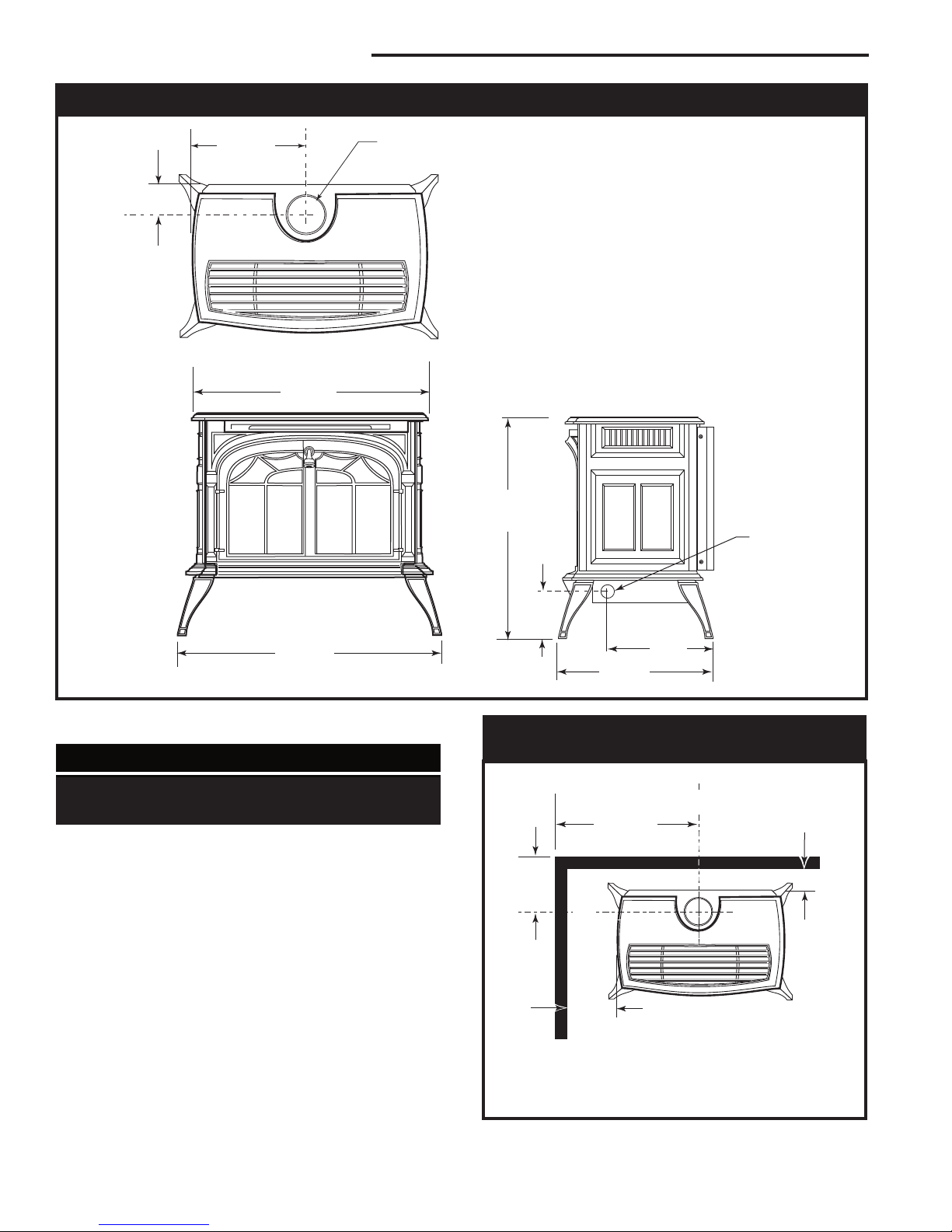
Stove Dimensions
Refer to Page 5 for Flue
Collar Centerline Dimensions
Fig. 1 Radiance dimensions.
Clearance Requirements
Minimum Clearances to
Combustible Materials
Measure side clearances as shown in Figures 2
through 5 from the outer edge of the cast iron stove
top. Measure rear clearances from the rear sheet metal
shroud.
The Radiance heater is approved for installation into
an alcove constructed of combustible materials to the
dimensions and clearances shown on this page.
The same clearances apply in a standard parallel
installation.
4
Parallel Installation:
Minimum Clearance and Flue Centerline
Stove Clearance: A: 4” (102 mm)
B: 6” (152 mm)
Pipe Centerline: C: 21⁷⁄₈” (556 mm)
ST128b
D: 8¹⁄₂” (216 mm)
Fig. 2 Parallel installation, minimum back and side clearances and flue centerlines.
20004409
Radiance Natural Vent Gas Heater
B
B
A
A
46"
(1168mm)
74"
(1880mm)
RA D I AN C E
42"
(1067 mm)
4"
(102 mm)
6"
(152 mm)
6"
(152 mm)
A
B
C
D
E
V
W
X
Y
Z
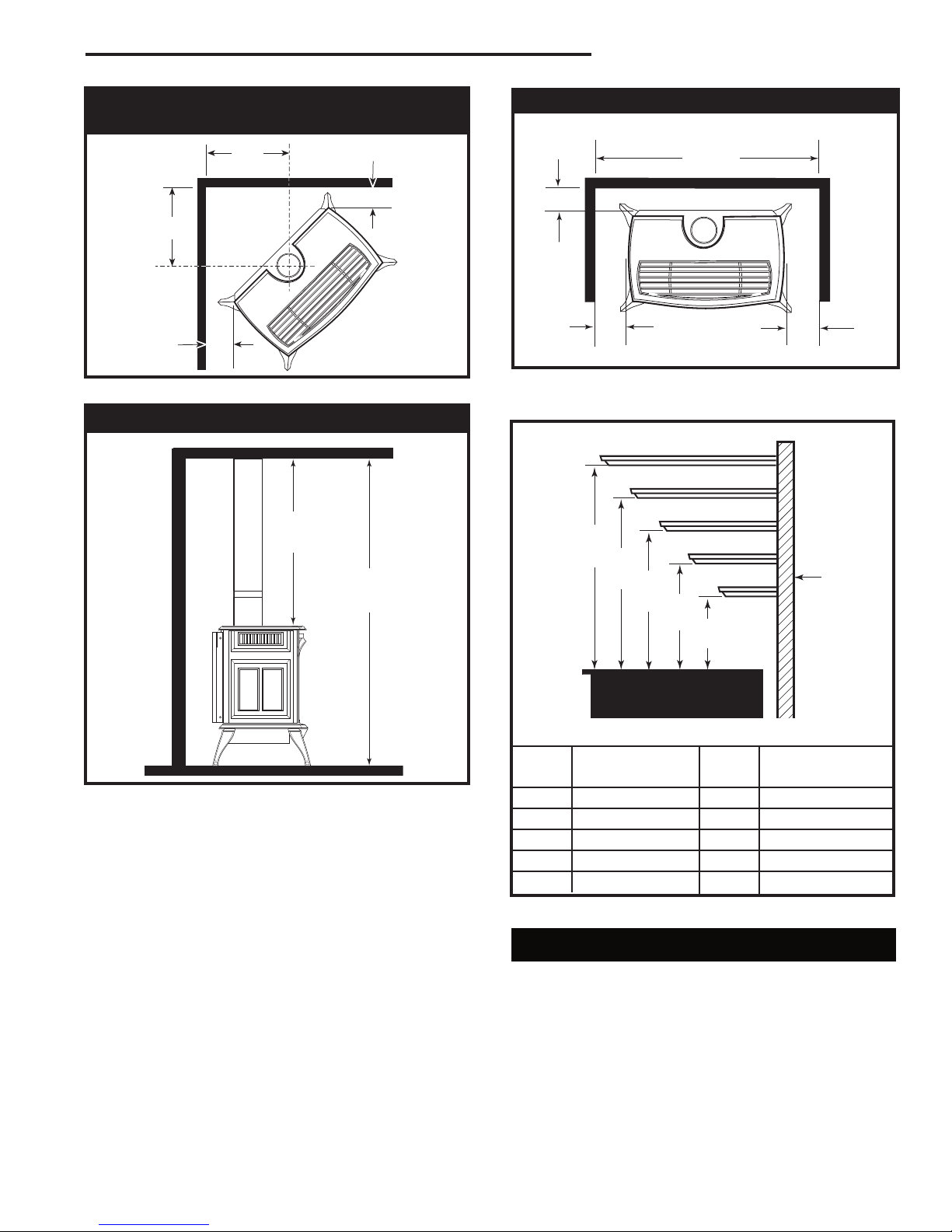
Corner Installation:
Minimum Clearance and Flue Centerline
Fig. 3 Corner installation requirements.
Ceiling Clearances
ST129b
Alcove Minimum Dimensions
ST130a
Fig. 5 The Radiance Natural Vent Stove is approved for
installation into alcoves built of combustible materials.
Fig. 4 Minimum ceiling clearance: minimum alcove height.
20004409
ST131b
Wall
ST694
Mantel Mantel from
Ref. Shelf Depth Ref. Stove Top
A 7
B 6” (152 mm) W 14
C 4
D 3” (75 mm) Y 11
E 1
Fig. 5a Minimum mantel clearance.
¹⁄₂” (190 mm) V 16” (406 mm)
¹⁄₂” (368 mm)
¹⁄₂” (114 mm) X 13” (330 mm)
¹⁄₂” (292 mm)
¹⁄₂” (38 mm) Z 10” (254 mm)
Hearth Requirements
The Radiance Heater must be installed on rigid flooring.
When the heater is installed directly on any combustible
surface other than wood flooring, a metal or wood panel
extending the full width and depth of the unit must be
used as the hearth. There are no other hearth requirements.
5
Radiance Natural Vent Gas Heater
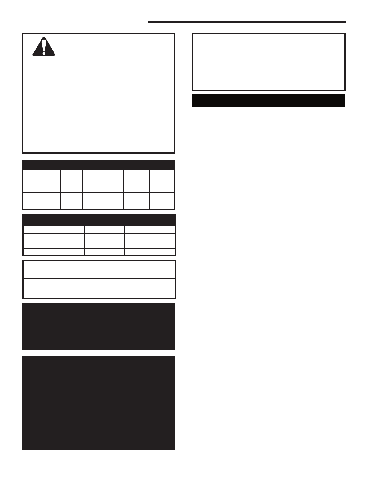
Warning:
• Always maintain required clearances
(air spaces) to nearby combustibles to
prevent fire hazard. Do not fill air spaces with
insulation. All venting components must maintain
a 1” (25 mm) clearance to combustible materials.
Maintain a 6” (150 mm) clearance when using
single wall pipe.
• The gas appliance and vent system must be
vented directly to the outside of the building and
never be attached to a chimney serving a separate solid fuel or gas-burning appliance.
• Refer to the manufacturer’s instructions included
with the venting system for complete installation
procedures.
Gas Specifications
Max. Min.
Input Input
Model Fuel Gas Control BTU/h BTU/h
RNVODRN Nat. Millivolt 35,000 25,000
RNVODRP Prop. Millivolt 35,000 27,000
Gas Inlet and Manifold Pressures
Natural LP (Propane)
Inlet Minimum 5.5” w.c. 11.0” w.c.
Inlet Maximum 14.0” w.c. 14.0” w.c.
Manifold Pressure 3.5” w.c. 10.0” w.c.
Radiance Direct Vent / Natural Vent
Certified to:
ANSI Z21.88-2005 / CSA Z2.33-2005
Vented Gas Fireplace Heaters
The installation must conform with local codes or, in
the absence of local codes, with the National Fuel
Gas Code, ANSI Z223.1/NFPA 54 - latest edition.
(EXCEPTION: Do not derate this appliance for altitude. Maintain the manifold pressure at 3.5” w.c. for
Natural Gas and 10” w.c. for Propane.)
High Elevations
Input ratings are shown in BTU per hour and are
certified without deration for elevations up to
4,500 feet (1,370 m) above sea level.
For elevations above 4,500 feet (1,370 m) in USA,
installations must be in accordance with the
current ANSI Z223.1/NFPA 54 and/or local codes
having jurisdiction.
In Canada, please consult provincial and/or local
authorities having jurisdiction for installations at
elevations above 4,500 feet (1,370 m).
WARNING: Improper installation, adjustment,
alteration, service or maintenance can cause injury or property damage. Refer to this manual for
correct installation and operational procedures.
For assistance or additional information consult
a qualified installer, service agency, or the gas
supplier.
Venting Requirements and Options
The Radiance must be properly connected to a listed
4” (102 mm) Type B venting system or to an approved
Class A masonry or factory-built chimney system. In
Canada, a complete relining of Class A chimney systems is required.
The Radiance Natural Vent stove will accept decora
tive 6” (150 mm) stove pipe around the Type B venting
system, for aesthetic purposes.
Complete Type B vent systems are available from a
number of manufacturers, and your dealer can usually
supply one. Pipe sections from different makers are not
interchangeable; do not mix pipe or vent sections from
different makers. Follow the vent system manufacturer’s
instructions exactly.
Decorative stove chimneys for B vent applications are
available through vent dealers.
The vent system should conform to specifications of the
National Fuel Gas Code, latest edition.
If connecting to a Class A chimney system, use 4” (102
mm) single wall or 4” Type B vent connector. Single wall
vent connector requires a minimum 6” (153 mm) clearance to combustible surfaces.
Exterior chimneys may be subject to flow reversal or
condensation. To lessen these conditions, enclose Type
B vents in an insulated chase, or reline exterior Class A
chimneys.
An approved pass-through device is always required,
whether the vent system passes through a wall or
a ceiling. Use a pass-through device from the same
maker who supplies the venting system.
Venting terminals shall not be recessed into a wall or
siding.
-
6
20004409
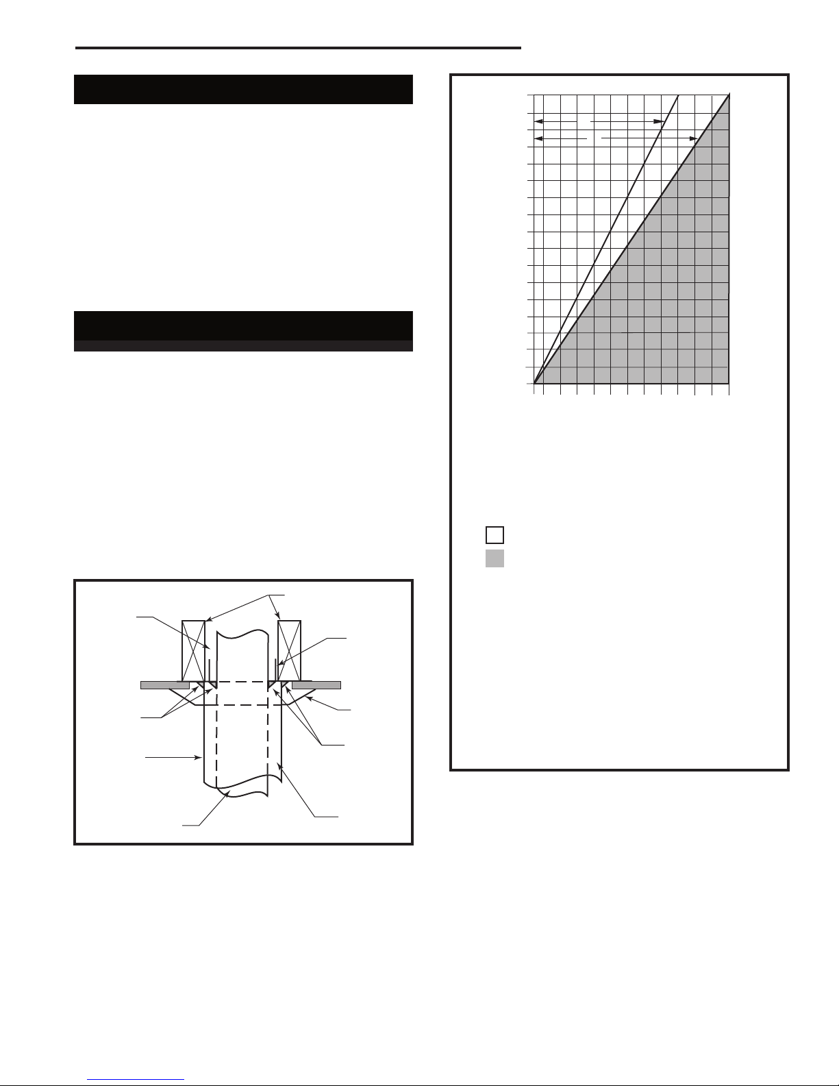
Vent Layout and Height Requirements
Venting Runs
A: Vertical installations up to 36 feet (12m) in
height. Up to an 18 ft. horizontal vent run can be
installed within the vent system using a
maximum of two 90-degree elbows or four
45-degree elbows.
B: Vertical installations up to 36 feet (12m) in
height. Up to a 24 ft. horizontal vent run can be
installed within the vent system using a
maximum of two 45-degree elbows.
(Ratio = 2/3, Hor./Vert.)
= Acceptable venting configuration
= Unacceptable venting configuration
NOTE: When venting staight vertical, without an
elbow, a minimum of 8 ft. vertical is required
off the top of the stove.
Horizontal Run (in feet)
Vertical Run (in feet)
(Measured from top of the unit before any elbow)
36
34
32
30
28
26
24
22
20
18
16
14
12
10
8
6
4
2
1 2 4 6 8 10 12 14 16 18 20 22 24
A
B
Venting for a Radiance can rise vertically through the
home, or can pass through an exterior wall and rise
along the outside of the home. Some codes require that
a Type B vent system rising on the outside of the home
be enclosed in a chase. Check your local codes for
requirements.
The minimum vent system height for the Radiance
Natural Vent Stove is 8 feet (2.43 m), (Fig. 7) measured
from the top of the stove. To determine the minimum
height the vent system must extend through or past the
roof, refer to the 1993 edition of the National Fuel Gas
Code.
Passing Through a
Combustible Wall or Ceiling
An approved pass-through device is always required
when a vent passes through a combustible wall or ceiling. Check with the maker of the vent system for the
correct listed devices that are available. A listed passthrough device is required whether or not the installation includes decorative pipe around the Type B venting
system. NOTE: It is essential to seal between the ceiling support (sometimes called a ‘firestop spacer’) and
the decorative pipe, if installed, with a high-temperature
silicone sealant. (Fig. 6)
Complete the venting system installation according to
the manufacturer’s instructions.
Air
Space as
Required
by Code
High-temperature
Silicone
Sealant
Decorative 6”
Pipe
Fig. 6 A ceiling pass-through, with decorative pipe around the
vent.
Listed 4” (102
mm) B-Vent
Joists
Ceiling
Support
Trim Collar
High-temperature
Silicone
Sealant
Air Space
ST361
Radiance Natural Vent Gas Heater
FP567b
Fig. 7 Vent termination window.
20004409
7
Radiance Natural Vent Gas Heater
Assembly Procedures
Tools Required
• Phillips screwdriver (stub) • power drill
• utility knife • reciprocating saw
• metal drill bit: size 28 (.140”/3.5 mm)
Unpack and Set Up the Stove
The Radiance is shipped on its back. Cut the shipping
straps and set stove upright.
Parts Bag Contents:
• On-Off switch, housing, and wiring harness
• 2 Bags of Lava Rock • 7 Screws
• Pipe Support Bracket • Fan Bracket*
• Door Handle (Operable) • Control Door Handle
• Owner Registration Card
• (4) CS, Hex Hd 3/8-16 x 1 GR 2-Z
• (4) Washer, FL 3/8-Z
*Used with stove’s having serials #’s starting at #1457
(RNVODRN), #1944 (RNVODRP).
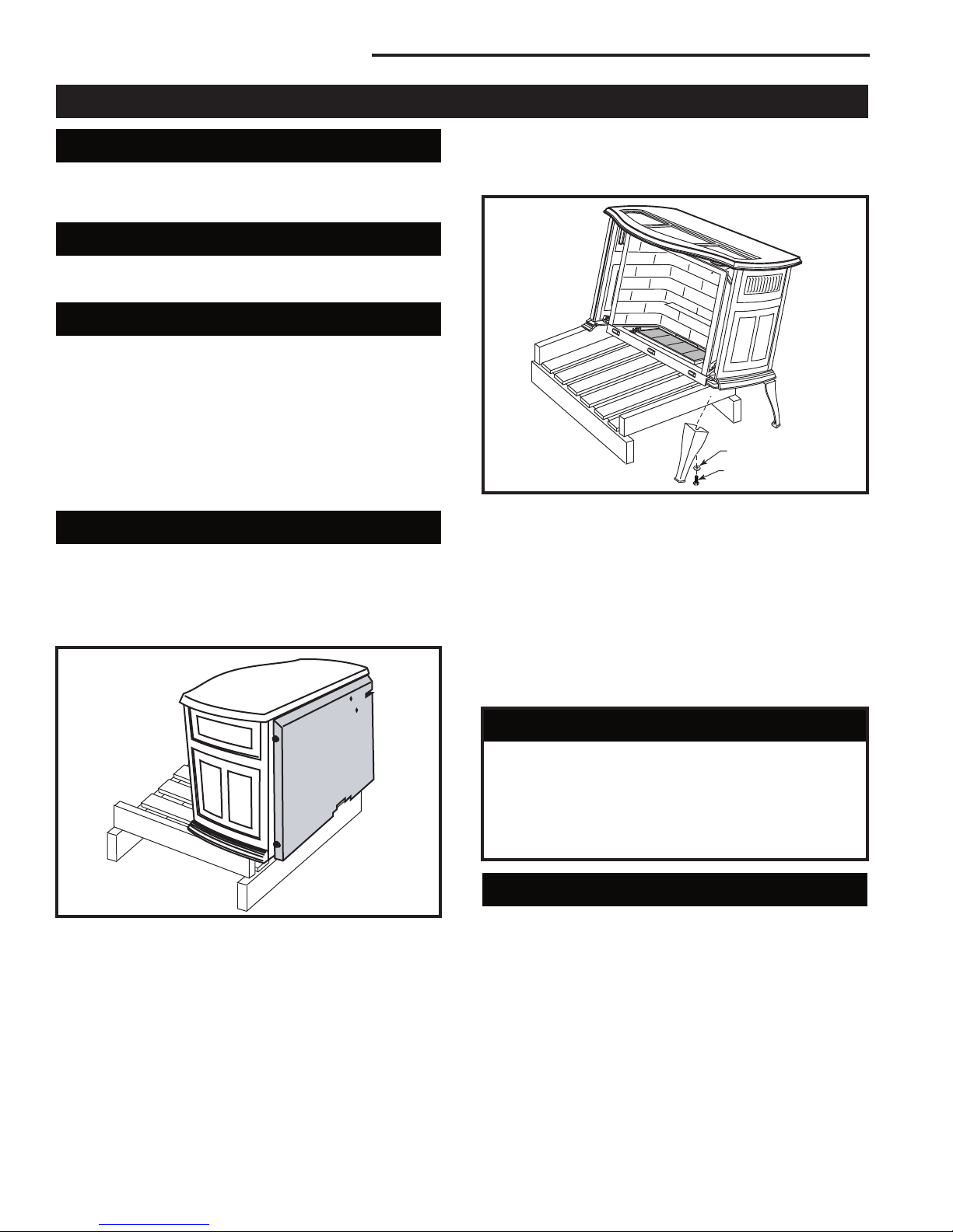
Unpack and Assemble Legs
The Radiance is shipped upright. Cut the shipping
straps and set stove upright.
1. Slide stove to the rear of the pallet just far enough to
access rear leg holes. Make sure the stove does not
tip over backwards. (Fig. 8)
CAUTION: To prevent valve tubing from being
crushed or damaged, make sure to rest valve on
wooden pallet.
Washer
ST721
Fig. 9 Carefully tip stove onto back legs. Leave pallet under
stove to keep stove from falling fully forward.
4. Have your assistant attach one leg using the hardware described.
5. Move the pallet to allow access to the other front leg
hole. Attach remaining leg.
6. Remove pallet and allow stove to gently rest on all
four legs.
7. Adjust leg levelers to compensate for irregularities in
the hearth.
Hex Head Bolt
ST720
Fig. 8 Slide stove back just far enough to access rear leg
holes.
2. Attach the rear legs using 3/8” hex head bolts and
flat washer supplied. Tighten with a 9/16” wrench or
socket.
3. Carefully tip the stove onto its rear legs. Adjust the
pallet to allow access to one of the front leg holes.
Be sure to leave the pallet under the stove to prevent
the stove from falling fully forward. (Fig. 9)
8
WARNING
This appliance is equipped with a three-prong
(grounded) plug for your protection against
shock hazard and should be plugged directly into
a properly grounded three-prong receptacle. Do
not cut or remove the grounding prong from this
plug.
Install the Optional Fan
These instructions are for stoves with serial numbers up
to #1456 (RNVODRN), #1943 (RNVODRP).
If you are installing the optional convection Fan Kit
#2767 (FK26), continue here. It is easiest to install fan
kit before connecting gas line. If you are not installing a
Fan Kit, proceed to Venting System Assembly.
20004409

Radiance Natural Vent Gas Heater
A
1. The fan kit includes a Blower Assembly and a Rheostat Assembly, connected by a cable. (Fig. 10) The
Blower Assembly mounts to the bottom rear of the
stove, and the Rheostat mounts to the left side of
the valve. The assembly includes a ‘snapstat’ which
automatically turns the fan On (or Off) above (or
below) approximately 109˚F. The Rheostat also provides a range of fan speed settings from Off (which
overrides the snapstat function) to High. Unpack and
inspect the Blower assembly. Confirm that the fan
spins freely.
Snapstat
Assembly
Not Used
on
Radiance
Rheostat
Assembly
ST146
Fig. 10 Fan kit components.
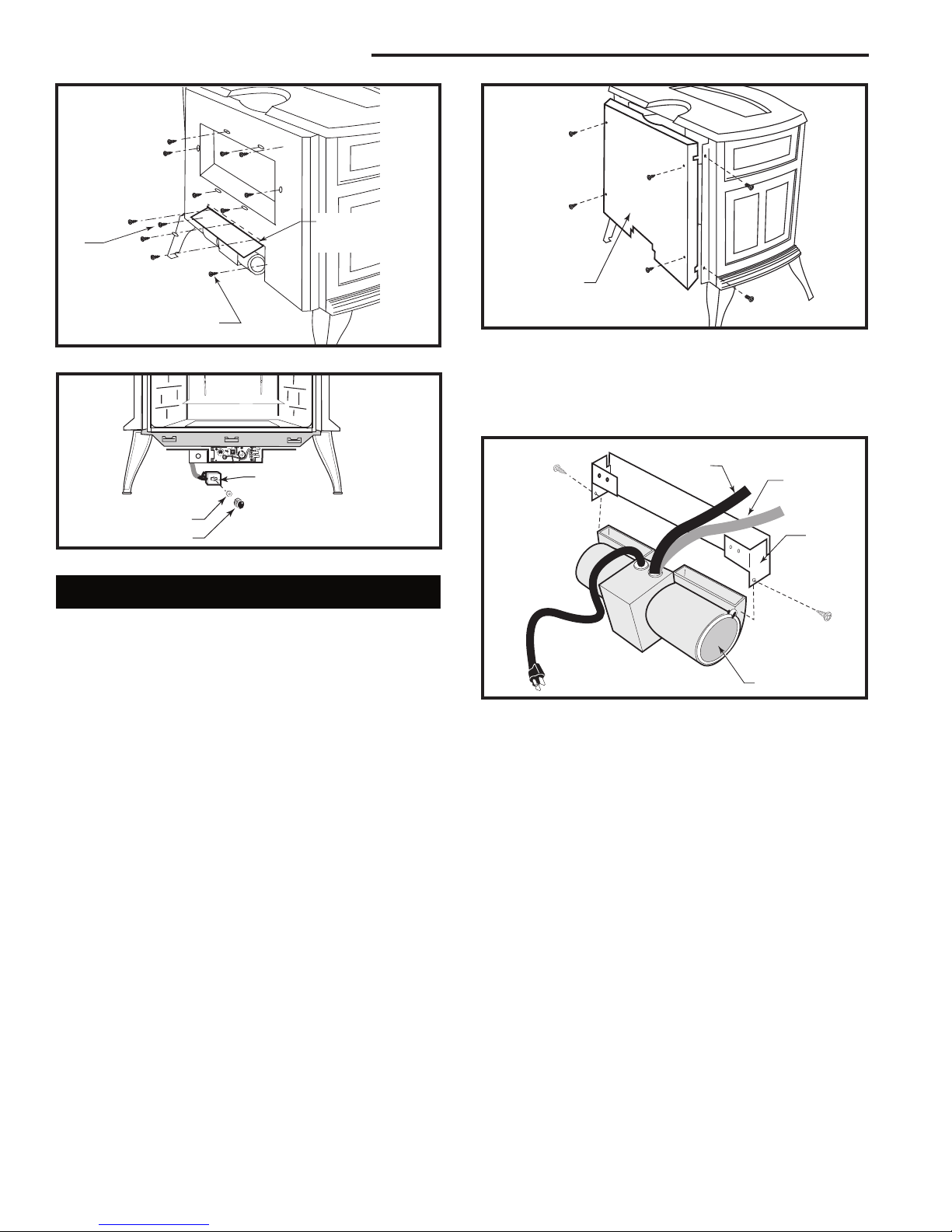
2. Remove the rear shroud. (Fig. 11) Use work gloves
to protect your hands. Remove the rear shroud
cover plate. Remove the six sheet metal screws (‘A’,
Fig. 9) surrounding the draft hood opening. Remove
the shroud and set it aside.
• Remove retaining nut from shaft of rheostat. (if
preinstalled)
• Insert the rheostat through the hole in the back
of the left side of the valve bracket, aligning the
locator pin with the smaller hole in that bracket.
• Thread the retaining nut onto the shaft of the
rheostat, tightening with a wrench. Do not overtighten.
• Attach the control knob to the rheostat shaft.
• Use the wire tie to secure the fan and rheostat
wire harnesses together.
1/4”-20 x
1/2” Hex
Bolts
Star
Washer
Snapstat
Housing
Snapstat
Bracket
Hex Nuts
Fig. 12 Position fan behind rear shroud.
Edge ‘A’
5. Attach the snapstat housing to the snapstat bracket
with two sheet metal screws and one #8 star washer.
(Fig. 12)
6. Attach the snapstat bracket, with the snapstat assembly attached to it, to the horizontal surface on
Slot
Fan Shield
ST369
the inside of the rear shroud. Use a sheet metal
Rear Shroud
screw. There are predrilled holes at each corner of
the panel for this. The vertical part of the snapstat
bracket should be 3/16” back from Edge ‘A’. (Fig. 12)
7. Attach the fan assembly to the rear shroud using two
1/4”-20 x 1/2” hex head bolts, two 1/4” -20 nuts and
one 1/4” star washer. (Fig. 12)
8. Reattach the stove’s rear shroud.
Rear Shroud
Cover Plate
(Shipping Position)
9. Reattach the rear shroud cover plate by fastening
it to the rear shroud as shown in Figure 13. The top
edge of the cover plate goes inside the rear shroud.
Reinstall and tighten the six sheet metal screws
around the draft hood opening; see ‘A’, Figure 13.
ST363
Fig. 11 Remove/replace rear shroud.
Use two screws from the fan kit to fasten the rear
shroud to the fan shield; refer to ‘A’, Figure 13.
Plug the fan cord into a standard grounded 110 volt
3. Position the fan behind the rear shroud. (Fig. 12)
household outlet.
Pass the fan rheostat assembly and snapstat assembly beneath the stove toward the front.
4. The rheostat control switch attaches to the left side
of the valve bracket at the front of the stove. (Fig.
14)
20004409
9
Radiance Natural Vent Gas Heater
Rear Shroud
A
Cover Plate
Rear Shroud
Assembly
A
Fig. 13 Attach rear shroud cover plate to the rear shroud.
Rheostat
Rheostat
Retaining Collar
Rheostat Knob
Fig. 14 Attach the fan rheostat.
ST371
ST347a
Install the Optional Fan
These instructions are for stoves with serial numbers
starting at #1457 (RNVODRN), #1944 (RNVODRP).
If you are installing the optional convection Fan Kit
#2767 (FK26), continue here. It is easiest to install fan
kit before connecting gas line. If you are not installing a
Fan Kit, proceed to Venting System Assembly.
1. The fan kit includes a Blower Assembly and a Rheostat Assembly, connected by a cable. The Blower
Assembly mounts to the bottom rear of the stove,
and the Rheostat mounts to the left side of the valve.
The assembly includes a ‘snapstat’ which automatically turns the fan On (or Off) above (or below)
approximately 109˚. The Rheostat also provides a
range of fan speed settings from Off (which overrides the snapstat function) to High. Unpack and
inspect the Blower assembly. Confirm that the fan
spins freely.
2. Loosen the four phillips head screws which secure
the rear shroud to the stove sides. (Fig. 15)
3. Carefully pull the shroud assembly away from the
rear of the stove.
4. With the rear shroud assembly in the upright position, set the bottom of the shroud on a padded
surface to prevent scratching the surface. Unfasten
the four phillips head screws which attach the outer
shroud to the inner duct assembly.
ST713
Fig. 15 Remove rear shroud.
5. Attach the fan assembly to the fan bracket provided
in the finish bag. Use the #10 sheet metal screws
provided with fan kit. Do not remove finger guard
screws. (Fig. 16)
Snapstat
Wire
Rheostat
Wire
Fan
Bracket
ST669
Fig. 16 Attach the fan assembly to the fan bracket.
Finger Guard
6. Connect snapstat leads. Disconnect the snapstat
module from the leads inside the snapstat bracket.
(Fig. 17) Bend open the snapstat bracket. Use
needle nose pliers to remove the black plastic grommet from the bracket. Discard the bracket. Insert the
grommet and wires into the large hole at the bottom
right corner of the inner shroud. Feed the snapstat
wire leads through the grommet into the stove interior. Connect the two wires to the two snapstat extension leads attached to the inner shroud or, on some
models, in between the inner and outer shroud.
7. Position the fan assembly so the ducts slide between
the inner and outer shroud. The inner shroud should
engage with the two slots in the ends of the bracket
so that bracket and shroud are interlocked. (Fig. 18)
Secure the bracket with the four sheet metal screws
provided in the finish bag.
10
20004409
 Loading...