

Vermont Castings RFSDV34 Installation Instructions And Homeowner's Manual

INSTALLER/CONSUMER
SAFETY INFORMATION
PLEASE READ THIS MANUAL
BEFORE INSTALLING AND USING
APPLIANCE
WARNING!
IF THE INFORMATION IN THIS
MANUAL IS NOT FOLLOWED
EXACTLY, A FIRE OR
EX P L OS I ON MAY RE S ULT
CAUSING PROPERTY
DAMAGE, PERSONAL INJURY
OR LOSS OF LIFE.
Freestanding
Direct Vent Gas Stove
with the LexFire Burn System™
Model: RFSDV34
FOR YOUR SAFETY
Installation and service must
be performed by a qualified
installer, service agency or the
gas supplier.
WHAT TO DO IF YOU SMELL GAS:
• Do not try to light any appliance.
• Do not touch any electric switch;
do not use any phone in your
building.
• Immediately call your gas supplier
from your neighbor’s phone. Follow
the gas suppliers instructions.
• If you cannot reach your gas
supplier call the re department.
DO NOT STORE OR USE GASOLINE
OR OTHER FLAMMABLE VAPORS
AND LIQUIDS IN THE VICINITY OF
THIS OR ANY OTHER
APPLIANCE.
Installation Instructions and
Homeowner’s Manual
INSTALLER: Leave this manual with the appliance.
CONSUMER: Retain this manual for future reference.
10003550 1/13 Rev. 13

RFSDV34 Freestanding Direct Vent Gas Stove
Table of Contents
PLEASE READ THE INSTALLATION & OPERATING INSTRUCTIONS BEFORE USING THIS APPLIANCE.
Thank you and congratulations on your purchase of an Vermont Castings Group gas stove.
IMPORTANT: Read all instructions and warnings carefully before starting installation. Failure to follow these
instructions may result in a possible re hazard and will void the warranty.
Installation & Operating Instructions
General Information, Warnings, Cautions ...........................................................................3
Requirements for the Commonwealth of Massachusetts ....................................................4
Unit Dimensions ..................................................................................................................5
Locating Your Stove ............................................................................................................6
Clearance to Combustibles .................................................................................................6
High Elevations ...................................................................................................................6
Gas Inlet and Manifold Pressures .......................................................................................6
Gas Specications ............................................................................................................... 6
Preparation ..........................................................................................................................6
Gas Line Installation ............................................................................................................6
Remote Switch Installation .................................................................................................. 7
General Venting Information
General Venting Information-Termination Location ............................................................8
General Information on Assembling Vent Pipes .................................................................. 9
How to Use the Vent Graph...................................... ......................................................... 10
Vertical Sidewall Applications & Installation ......................................................................10
Below Grade Installations.. ................................................................................................ 13
Vertical Through-the-Roof Applications & Installations ......................................................14
Venting Components .........................................................................................................16
Operating Instructions
Glass Information ..............................................................................................................17
Window Frame Assembly Removal ................................................................................... 17
Glass Cleaning .................................................................................................................. 17
Log Set and Lava Rock Material Installation ..................................................................... 17
Flame & Temperature Adjustment .....................................................................................19
Flame Characteristics ........................................................................................................ 19
Lighting & Operating Instructions ......................................................................................0
Troubleshooting NOVA SIT 80 Millivolt Valve .................................................................. 1
Instructions for RCSITE .....................................................................................................
Troubleshooting ................................................................................................................ 5
Maintenance
Cleaning the Standing Pilot Control System .....................................................................7
Wiring Diagrams ................................................................................................................8
Replacement Parts ...................................................................................................................... 9
Optional Accessories
Fan Kits .............................................................................................................................31
Optional Brass Trim Kit ...................................................................................................... 3
Remote Control Units ........................................................................................................ 3
Warranty ....................................................................................................................................... 35
Energuide ...................................................................................................................................... 36
10003550
RFSDV34 Freestanding Direct Vent Gas Stove
7!2.).'
(/4',!337),,
#!53%"52.3
$/./44/5#(',!33
5.4),#//,%$
.%6%2!,,/7#(),$2%.
4/4/5#(',!33
Installation & Operating Instructions
This gas stove should be installed by a qualied installer in
accordance with local building codes and with current CSA-B149.1
Installation codes for Gas Burning Appliances and Equipment.
If the unit is being installed in a mobile home, the installation
should comply with the current CAN/USA Z40.4 code. For USA
Installations follow local codes and/or the current National Fuel
Gas Code. ANSI Z3.1/NFPA 54.
FOR SAFE INSTALLATION AND OPERATION PLEASE NOTE
THE FOLLOWING:
1 . This unit gives off high temperatures and should be located out
of high trafc areas and away from furniture and draperies.
. Children and adults should be alerted to the hazards of the
high surface temperatures of this unit and should stay away
to avoid burns or ignition of clothing.
3. CAUTION: Due to high glass surface temperature children
should be carefully supervised when in the same room
as unit.
4. Young children should be carefully supervised when they
are in the same room as the appliance. Toddlers, young
children and others may be susceptible to accidental
contact burns. A physical barrier is recommended if there
are at risk individuals in the house. To restrict access to
a replace or stove, install an adjustable safety gate to
keep toddlers, young children and other at risk individuals
out of the room and away from hot surfaces.
5. Under no circumstances should this unit be modied. Parts
removed for servicing should be replaced prior to operating
this unit again.
6. Installation and any repairs to this unit must be performed by
a qualied installer, service agency or gas supplier. A professional service person should be contacted to inspect the unit
annually. More frequent cleaning may be required due to excess
lint and dust from carpeting, bedding material, etc.
7. Control compartments, burners and air passages in this unit
should be kept clean and free of dust and lint. Make sure that
the gas valve and pilot light are turned off before you attempt
to clean this unit.
8. The venting system (chimney) of this unit should be checked
at least once a year and if needed your venting system should
be cleaned.
9. Keep the area around your unit clear of combustible materials,
gasoline and other ammable vapour and liquids. This unit
should not be used as a drying rack for clothing, nor should
Christmas stockings or decorations be hung on or around the
unit.
10. Under no circumstances should any solid fuels (wood, coal,
paper or cardboard etc.) be used in this unit.
11. The ow of combustion and ventilation air must not be obstructed
in any way.
10003550
1. When the unit is installed directly on carpeting, vinyl tile or
any combustible material other than wood, this unit must be
installed on a metal or wood panel extending the full width and
depth of the unit.
13. This unit requires adequate ventilation and combustion air to
operate properly.
14. This unit must not be connected to a chimney ue serving a
separate solid fuel burning unit.
15. When the unit is not in use it is recommended that the gas
control valve be left in the OFF position.
16. This appliance is approved for bedroom installations in the
U.S. and Canada.
RFSDV34
Certied To
ANSI Z21.88 / CSA 2.33 Latest Editions
Vented Gas Fireplace Heaters
This appliance may be installed in an aftermarket
permanently located, manufactured home or mobile
home, where not prohibited by local codes.
This appliance is only for use with the type of gas
indicated on the rating plate. This appliance is not
convertible for use with other gases, unless a certied
kit is used.
Model RFSDV34RMH can be installed in manufactured
(mobile) homes by OEM.
IMPORTANT:
PLEASE REVIEW THE FOLLOWING CAREFULLY
Remove any plastic from from parts before turning the
unit ON.
It is normal for stoves fabricated of steel to give off some
expansion and/or contraction noises during the start up
or cool down cycle. Similar noises are found with your
furnace heat exchanger or car engine.
It is not unusual for your gas stove to give off some odor
the rst time it is burned. This is due to the curing of the
paint and any undetected oil from the manufacturing
process.
Please ensure that your room is well ventilated-open
all windows.
It is recommended that you burn your stove for at least
ten (10) hours the rst time you use it. If the optional fan
kit has been installed, place the fan switch in the “OFF”
position during this time.
Proposition 65 Warning: Fuels used in gas, woodburning or oil red appliances, and the products of combustion
of such fuels, contain chemicals known to the State of
California to cause cancer, birth defects and other reproductive harm.
California Health & Safety Code Sec. 549.6
3

RFSDV34 Freestanding Direct Vent Gas Stove
Installation & Operating Instructions
Requirements for the Commonwealth of
Massachusetts
All gas tting and installation of this heater shall only be
done by a licensed gas tter or licensed plumber.
For all side wall horizontally vented gas fueled equipment
installed in every dwelling, building or structure used in whole
or in part for residential purposes, including those owned
or operated by the Commonwealth and where the side wall
exhaust vent termination is less than seven (7) feet above
nished grade in the area of the venting, including but not
limited to decks and porches, the following requirements
shall be satised:
Installation of Carbon Monoxide Detectors
At the time of installation of the side wall horizontal vented
gas fueled equipment, the installing plumber or gas tter
shall observe that a hard wired carbon monoxide detector
with an alarm is installed on each additional level of the
dwelling, building or structure served by the side wall
horizontally vented gas fueled equipment. It shall be the
responsibility of the property owner to secure the services
of qualied licensed professionals for the installation of
hard wired carbon monoxide detectors.
In the event that the side wall horizontally vented gas fueled
equipment is installed in a crawl space or an attic, the hard
wired carbon monoxide detector with alarm and battery
back-up may be installed on the next adjacent oor level.
In the event that the requirements of this subdivision can not
be met at the time of completion of installation, the owner
shall have a period of thirty (30) days to comply with the
above requirements; provided, however, that during said
thirty (30) day period, a battery operated carbon monoxide
detector with an alarm shall be installed.
Approved Carbon Monoxide Detectors
Each carbon monoxide detector as required in accordance
with the above provisions shall comply with NFPA 70 and
ANSI/UL 034 listed and IAS certied.
Signage
A metal or plastic identication plate shall be permanently
mounted to the exterior of the building at a minimum height
of eight (8) feet above grade directly in line with the exhaust
vent terminal for the horizontally vented gas fueled heating
appliance or equipment. The sign shall read, in print size no
less than one-half (1/) inch in size, “GAS VENT DIRECTLY
BELOW, KEEP CLEAR OF ALL OBSTRUCTIONS”.
Inspection
The state or local gas inspector of the side wall horizontally
vented gas fueled equipment shall not approve the
installation unless, upon inspection, the inspector observes
carbon monoxide detectors and signage installed in
accordance with the provisions of 48 CMR 5.08()(a)1
through 4.
Exemptions
The following equipment is exempt from 48 CMR
5.08()(a)1 through 4:
• The equipment listed in Chapter 10 entitled “Equipment
Not Required To Be Vented” in the most current edition
of NFPA 54 as adopted by the Board; and
• Product Approved side wall horizontally vented gas fueled
equipment installed in a room or structure separate from
the dwelling, building or structure used in whole or in
part for residential purposes.
MANUFACTURER REQUIREMENTS
Gas Equipment Venting System Provided
When the manufacturer of Product Approved side wall
horizontally vented gas equipment provides a venting
system design or venting system components with the
equipment, the instructions provided by the manufacturer
for installation of the equipment and the venting system
shall include:
• Detailed instructions for the installation of the venting
system design or the venting system components;
and
• A complete parts list for the venting system design or
venting system.
Gas Equipment Venting System NOT Provided
When the manufacturer of a Product Approved side wall
horizontally vented gas fueled equipment does not provide
the parts for venting the ue gases, but identies “special
venting systems”, the following requirements shall be
satised by the manufacturer:
• The referenced “special venting system” instructions shall
be included with the appliance or equipment installation
instructions; and
• The “special venting systems” shall be Product
Approved by the Board, and the instructions for that
system shall include a parts list and detailed installation
instructions.
A copy of all installation instructions for all Product Approved
side wall horizontally vented gas fueled equipment, all
venting instructions, all parts lists for venting instructions,
and/or all venting design instructions shall remain with
the appliance or equipment at the completion of the
installation.
4
10003550
RFSDV34 Freestanding Direct Vent Gas Stove
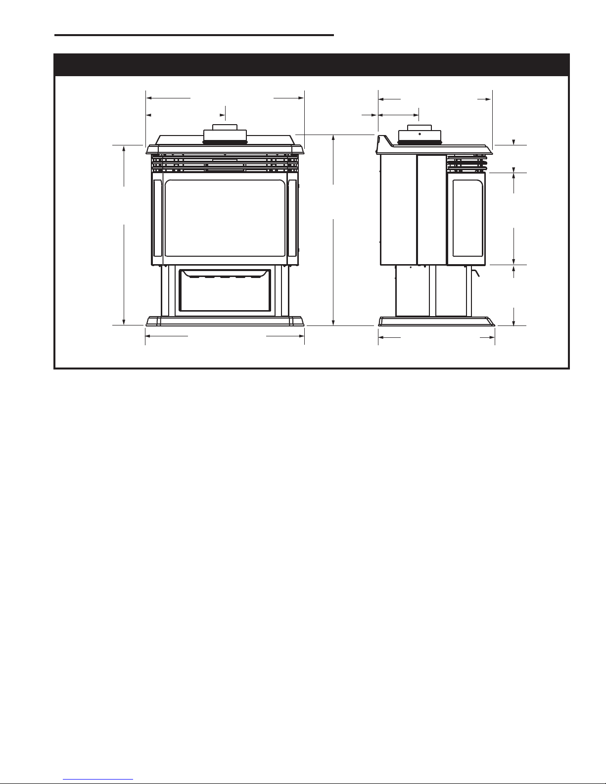
2656M” (667 mm)
30”
(762 mm)
1356” (333 mm)
2656M” (667 mm)
3156O”
(800 mm)
66”
(162 mm)
1956O” (495 mm)
456O”
(114 mm)
1556O”
(394 mm)
10”
(254 mm)
196” (492 mm)
Stove Dimensions
Fig. 1 Stove specications and framing dimensions.
10003550
5
RFSDV34 Freestanding Direct Vent Gas Stove
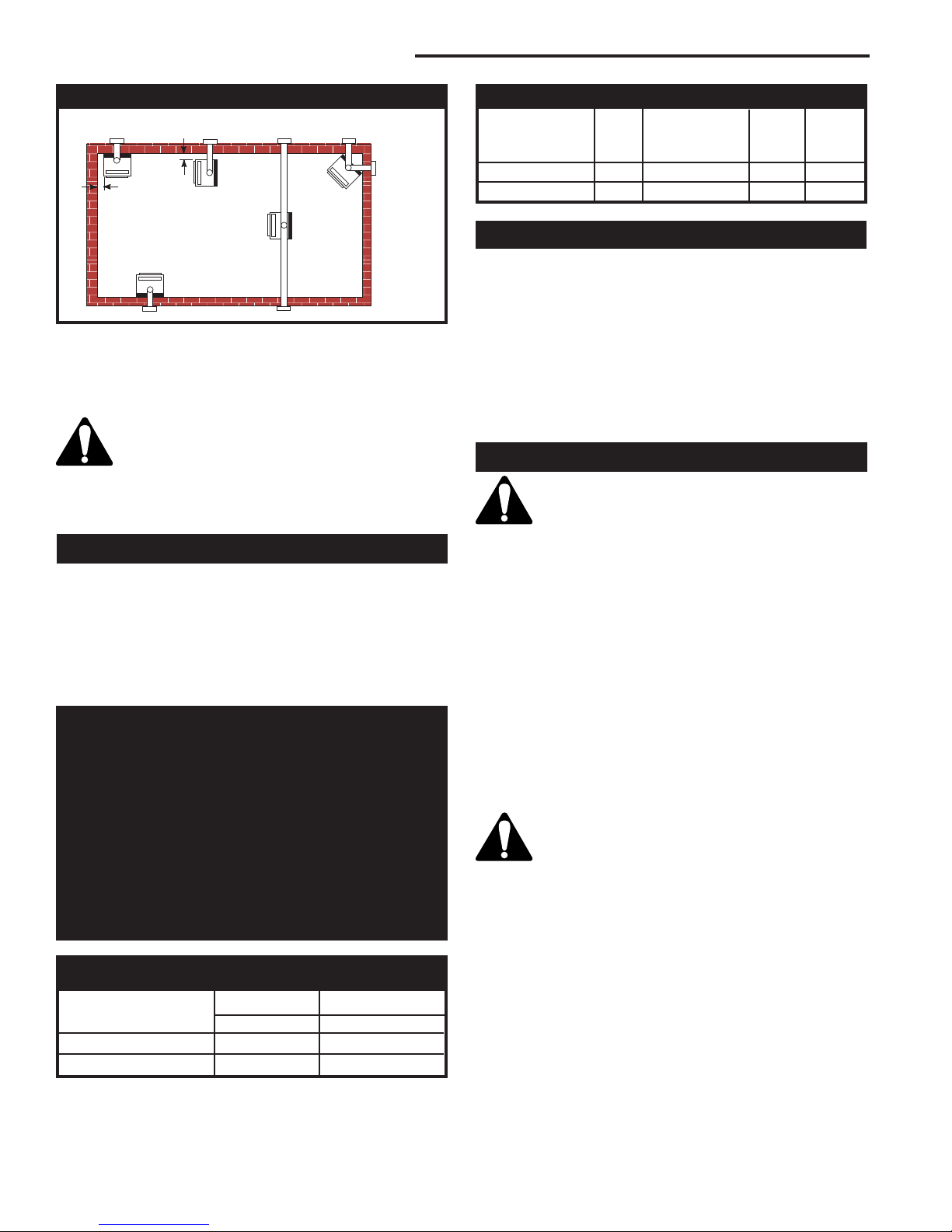
12” (305 mm)
A
12”
(305 mm)
B
E
C
D
Locating Your Stove
FP160
Fig. 2 Locate gas stove.
A) Flat on wall* B) Room Divider* C) Island
D) Cross Corner E) Flat on wall corner
Note (Fig. 2): *(A) and (B) must maintain a 1” (305 mm)
clearance between the wall and side glass of stove.
There is a minimum vertical rise required for
the venting, which varies depending on the
application. The maximum horizontal run
also has restrictions. Before starting the installation, become familiar with venting instructions starting on Page 9.
Clearance to Combustibles
Top of Unit to Ceiling ............................... 36” (914 mm)
Appliance
Back ........................................................ 0” (0 mm)
Side ................................................... 1” (305 mm)
Floor ........................................................ 0” (0 mm)
Corner ............................. 0” (0 mm) to Back Edges
Vent Pipe ............................................... 1” (5 mm)
High Elevations
Input ratings are shown in BTU per hour and are
certied without deration for elevations up to 4,500
feet (1,370 m) above sea level.
For elevations above 4,500 feet (1,370 m) in USA,
installations must be in accordance with the current ANSI Z223.1/NFPA 54 and/or local codes having
jurisdiction.
In Canada, please consult provincial and/or local
authorities having jurisdiction for installations at
elevations above 4,500 feet (1,370 m).
Gas Inlet and Manifold Pressures
Natural LP (Propane)
Inlet Minimum 5.5” w.c. 11.0” w.c.
Inlet Maximum 14.0” w.c. 14.0” w.c.
Manifold Pressure 3.5” w.c. 10.0” w.c.
Gas Specications
Max. Min.
Input Input
Model Fuel Gas Control BTU/h BTU/h
RFSDV34TSRN Nat Millivolt Hi/Lo 30,000 1,000
RFSDV34TSRP Prop Millivolt Hi/Lo 30,000 ,500
Preparation
The use of wallpaper adjacent to this stove is not recommended, as the high heat given off by this stove may
adversely affect the binders in the adhesive used to apply
the wallpaper.
Before beginning, remove the window frame assembly
from the stove. Also check to make sure there is not hidden damage to the stove. Take a minute and plan out the
gas, vent and electrical supply. Refer to Window Frame
Assembly Removal Section.
Gas Line Installation
When purging gas line, the front window frame
assembly must be removed.
The gas pipeline can be brought in through the rear of
the stove as well as the bottom. Knockouts are provided
on the bottom behind the valve to allow for the gas pipe
installation and testing of any gas connection. It is most
convenient to bring the gas line in from the rear right side of
the valve as this allows fan installation or removal without
disconnecting the gas line.
The gas line connection can be made with properly tinned
3/8” copper tubing, 3/8” rigid pipe or an approved ex connector. Since some municipalities have additional local
codes, it is always best to consult your local authority and
the National Fuel Gas Code, ANSI Z3.1/NFPA 54 in the
USA or the CSA-B149.1 installation codes.
Always check for gas leaks with a mild soap and water
solution. Do not use an open ame for leak
testing.
The gas control is equipped with a captured screw
type pressure test point, therefore it is not necessary to
provide a 1/8” test point up stream of the control.
When using copper or ex connector use only approved
ttings. Always provide a union when using black iron pipe
so that the gas line can be easily disconnected for burner
or fan servicing . See gas specications for pressure details
and ratings.
The stove valve must not be subjected to any test pressures exceeding 1/ psi. Isolate or disconnect this or any
other gas appliance control from the gas line when pressure testing.
6
10003550
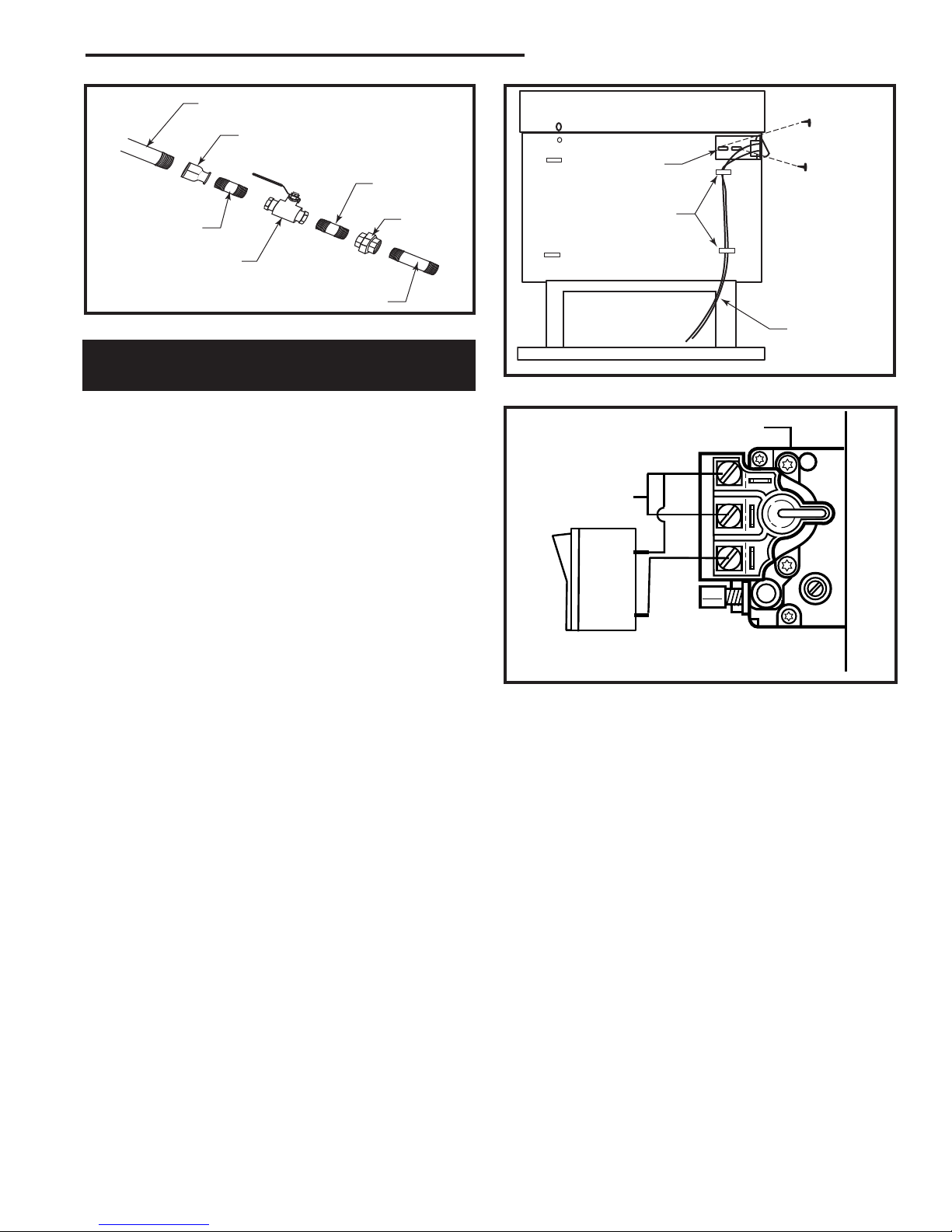
1/” Gas Supply
P
I
L
O
T
TPTH
TP
TH
1/” x 3/8” Reducer
3/8” Nipple
RFSDV34 Freestanding Direct Vent Gas Stove
Screw
ON/OFF Switch
Assembly
(through existing
hole)
Screw
3/8” Union
CFM106
3/8” Nipple
3/8” x 3/8”
Shut-Off Valve
3/8” Nipple
Fig. 3 Typical gas line connection.
Installation of Remote Switch
for RSN/RSP Gas Valve
NOTES: The remote ON/OFF switch cannot be tted
to units using the Honeywell Radio Frequency control valve.
If the stove has been tted with the RCSITEA Control, the ON/OFF function is controlled by the remote
handset or receiver switch. Refer to Page 22.
Install the ON/OFF switch assembly on either the rear
right or rear left side of the stove.
1. Remove the screw at the back of the cabinet top either
on the left or the right side of the stove.
. Position switch assembly onto the back of the stove,
then fasten two () screws as shown in Figure 3.
3. Attach wiring under the clips on the rear casing (Fig. 4)
and install wiring through the rear opening of the stove
before connecting to the valve as shown in Figure 5.
Clips
Wiring for
Millivolt Gas
Valves
FP161
Fig. 4 Attach wiring under clips on rear casing.
Valve
SIT Valve
Thermopile
ON/OFF Switch or
Millivolt Thermostat
Fig. 5 Install wiring to switch before connecting to valve.
FP16
10003550
7
RFSDV34 Freestanding Direct Vent Gas Stove
V
X
X
X
D
E
B
B
B
C
B
M
B
A
J
K
F
L
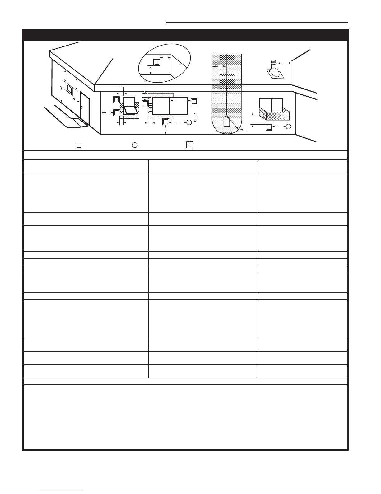
VENT TERMINATION AIR SUPPLY INLET
AREA WHERE TERMINAL IS NOT PERMITTED
H
I
Fixed
Closed
Operable
Operable
Fixed
Closed
B
INSIDE
CORNER DETAIL
A
G
CFM145a
V
V
V
V
V
V
V
V
N
General Venting Information - Termination Location
Canadian Installations1 US Installations
2
A = Clearance above grade, veranda, porch, 1” (30cm) 1” (30cm)
deck, or balcony
B = Clearance to window or door that may be 6” (15cm) for appliances 6” (15cm) for appliances
opened < 10,000Btuh (3kW), 1” (30cm) < 10,000 Btuh (3kW), 9”
for appliances > 10,000 Btuh (3kW) and (3cm) for appliances > 10,000
< 100,000 Btuh (30kW), 36” (91cm) Btuh (3kW) and < 50,000 Btuh
for appliances > 100,000 Btuh (30kW) (15kW), 1” (30cm) for
appliances > 50,000 Btuh (15kW)
C = Clearance to permanently closed window 1” (305mm) recommended to 1” (305mm) recommended to
prevent window condensation prevent window condensation
D = Vertical clearance to ventilated soft located
above the terminal within a horizontal 18” (458mm) 18” (458mm)
distance of ’ (610mm) from the center
line of the terminal
E = Clearance to unventilated soft 1” (305mm) 1” (305mm)
F = Clearance to outside corner see next page see next page
G = Clearance to inside corner (see next page) see next page see next page
H = Clearance to each inside of center line 3’ (91cm) within a height of 15’ (5m) 3’ (91cm) within a height of 15’
extended above meter/regulator assembly above the meter/regulator assembly (5m) above the meter/regulator
assy
I = Clearance to service regulator vent outlet 3’ (91cm) 3’ (91cm)
J = Clearance to nonmechanical air supply inlet 6” (15cm) for appliances < 10,000 6” (15cm) for appliances
to building or the combustion air inlet to any Btuh (3kW), 1” (30cm) for < 10,000 Btuh (3kW), 9”
other appliances appliances > 10,000 Btuh (3kW) and (3cm) for appliances > 10,000
< 100,000 Btuh (30kW), 36” (91cm) Btuh (3kW) and < 50,000 Btuh
for appliances > 100,000 Btuh (30kW) (15kW), 1” (30cm) for
appliances > 50,000 Btuh (15kW)
K = Clearance to a mechanical air supply inlet 6’ (1.83m) 3’ (91cm) above if within 10
feet (3m) horizontally
L = Clearance above paved sidewalk or paved 7’ (.13m)† 7’ (.13m)†
driveway located on public property
M = Clearance under veranda, porch, deck or 1” (30cm)* 1” (30cm)*
balcony
N = Clearance to any other obstruction within a horizontal distance of 18” (450mm).
1 In accordance with the current CSA-B149 Installation Codes
In accordance with the current ANSI Z3.1/NFPA 54 National Fuel Gas Codes
† A vent shall not terminate directly above a sidewalk or paved driveway which is located between two single family dwellings and
serves both dwellings
* only permitted if veranda, porch, deck or balcony is fully open on a minimum sides beneath the oor:
NOTE: 1. Local codes or regulations may require different clearances.
. The special venting system used on Direct Vent Stoves are certied as part of the appliance, with clearances tested and
approved by the listing agency.
3. Vermont Castings Group assumes no responsibility for the improper performance of the appliance when the venting system does
not meet these requirements.
Fig. 6 Termination location requirements.
8
10003550
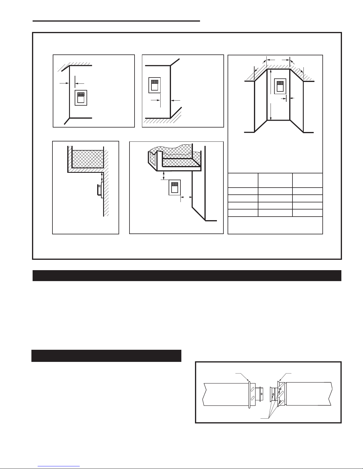
Outside Corner
Inside Corner
Termination Clearances
Termination clearances for buildings with combustible and noncombustible exteriors.
G =
Combustible
6" (152 mm)
Noncombustible
2" (51 mm)
F =
Combustible
6" (152 mm)
Noncombustible
2" (51 mm)
G
Balcony -
with no side wall
M =
Combustible &
Noncombustible
12" (305 mm)
M
Balcony -
with perpendicular side wall
M = 12" (305 mm)
P = 6” (152 mm)
M
F
Alcove Applications*
C
D
C
E
V
V
Combustible &
Noncombustible
E = Min. 2” (51 mm) for
non-vinyl sidewalls
Min. 12” (305 mm) for
vinyl sidewalls
O = 8’ (2.4 m) Min.
O
P
V
V
V
*NOTE: Termination in an alcove space (spaces open only on one side and with an overhang) is permitted with the dimensions
specied for vinyl or non-vinyl siding and softs. 1. There must be a 3’ (914 mm) minimum between termination caps. . All
mechanical air intakes within 10’ (1 m) of a termination cap must be a minimum of 3’ (914 mm) below the termination cap. 3. All
gravity air intakes within 3’ (914 mm) of a termination cap must be a minimum of 1’ (305 mm) below the termination cap.
Fig. 6a Termination clearances.
Canadian Installations:
General Information on Assembling Vent Pipes
The venting system must be installed in accordance with
the current CSA-B149 .1 installation code.
USA Installations:
The venting system must conform with local codes and/or the
current National Fuel Gas code ANSI Z3.1/NFPA 54.
Only venting components manufactured by Vermont Castings Group can be used in Direct Vent systems.
Twist Lock Pipes
RFSDV34 Freestanding Direct Vent Gas Stove
No.
of Caps D
1 3’ (.9 mm) x D
6’ (1.8 m) 1 x D
3 9’ (.7 m) /3 x D
4 1’ (3.7 m) 1/ x D
D
= # of Termination caps x 3
Min.
C
= ( / # termination caps) x D
Max.
To join the twist lock pipes together, simply align the beads
of the male end with the grooves of the female end, then
while bringing the ends together, twist the pipe until the
ange on the female end contacts the external ange
on the male end. It is recommended that you secure the
joints with three (3) sheet metal screws, however this is
not mandatory with twist lock pipe.
To make it easier to assemble the joints we suggest putting
a lubricant (Vaseline or similar) on the male end of the twist
lock pipe prior to assembly.
C
Min.
Max.
Actual
Actual
Actual
Actual
Actual
584-15
When using Vermont Castings Group twist-lock pipe it is
not necessary to use sealant on the joints. The only areas
of the venting system that need to be sealed with high
temperature silicone sealant are the collars on the stove
and termination, and the sliding joint of any telescopic vent
section used in the system.
10003550
Male End
Female End
Fig. 7 Twist-lock pipe joints.
Screw Holes
TWL100
9
RFSDV34 Freestanding Direct Vent Gas Stove
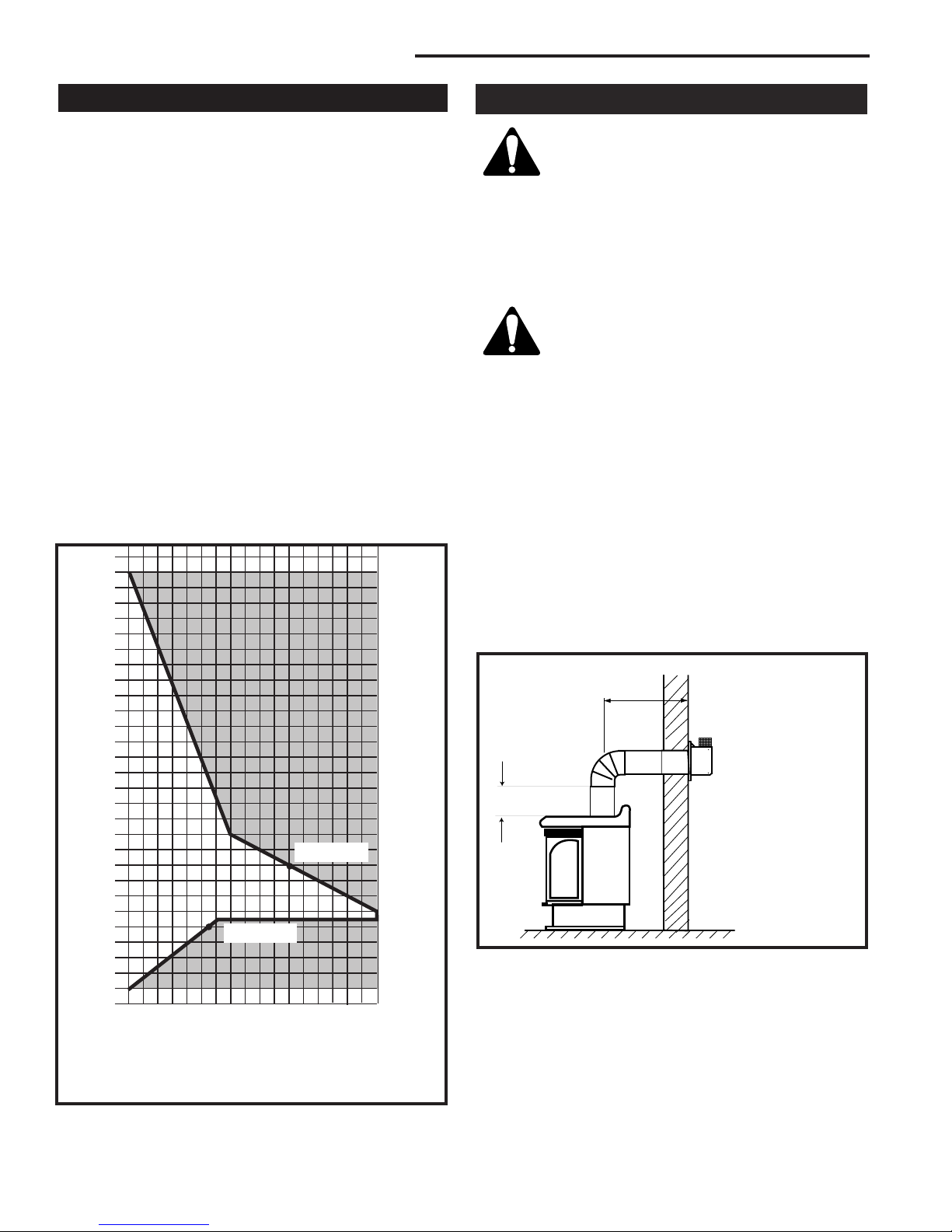
3
4
5
6
7
8
9
10
11
12
13
14
15
16
17
18
19
20
21
22
23
24
25
26
27
28
29
30
3 4 5 6 7 8 9 10 11 12 13 14 15 16 17 18 19 20
Example: A
Example: B
36”
(914 mm)
x
How to Use the Vent Graph
The vent chart should be read in conjunction with the
following vent installation instructions to determine the
relationship of the vertical and horizontal dimensions of
the vent system.
1. Determine the height of the center of the horizontal vent
pipe exiting through the outer wall. Using this dimension
on the Sidewall Vent Graph (Fig. 8), locate the point
intersecting with the slanted graph line.
. From the point of this intersection, draw a vertical line
to the bottom of the graph.
3. Select the indicated dimension, and position the stove
in accordance with same.
Example A:
If the vertical dimension from the oor of the unit is 11’
(3.4m) the horizontal run to the face of the outer wall must
not exceed 14’ (4.3 m).
Example B:
If the vertical dimension from the oor of the unit is 7’
(.14m), the horizontal run to the face of the outer wall
must not exceed 8¹⁄₂’ (.6 m).
Vertical dimension from the oor of the stove to
Vertical Sidewall Applications
Since it is very important that the venting
system maintain its balance between the combustion air intake and the ue gas exhaust,
certain limitations as to vent congurations
apply and must be strictly adhered to.
The vent graph showing the relationship between vertical
and horizontal side wall venting will help to determine the
various dimensions allowable.
Minimum clearance between vent pipes and combusti-
ble materials is one 1” (25mm) on top, bottom
and sides unless otherwise noted.
When the vent termination exits through founda-
tions less than 0” (508 mm) below siding outcrop,
the vent pipe must ush up with the siding.
It is always best to locate the stove in such a way that
minimizes the number of offsets and horizontal vent length
of vent pipe from the ue collar of the stove to the face of
the outer wall.
Horizontal plane means no vertical rise exists on this portion of the vent assembly.
• The maximum number of 90° elbows per side wall
installations is three (3).
• For RFSDV4 and RFSDV34 models, the maximum
horizontal rn for a minimum 1” (305 mm) vertical rise
is 3’ (914 mm). (Fig. 9)
Fig. 8 Sidewall venting graph. (Dimensions in feet)
10
Horizontal dimension from the outside face of the wall to
the center of the stove vent ange
Sidewall vent graph showing the relationship between vertical
and horizontal dimensions for a Direct Vent ue system.
the center of the horizontal vent pipe
RFSDV4
RFSDV34
x = 1” (305 mm)
FP1495
Fig. 9 Maximum horizontal run.
• If a 90° elbow is used in the horizontal vent run (level
height maintained) the maximum horizontal vent length
is reduced by 36” (914 mm). (Fig. 10) This does not
apply if the 90° elbows are used to increase or redirect
a vertical rise. (Fig. 11)
10003550
RFSDV34 Freestanding Direct Vent Gas Stove
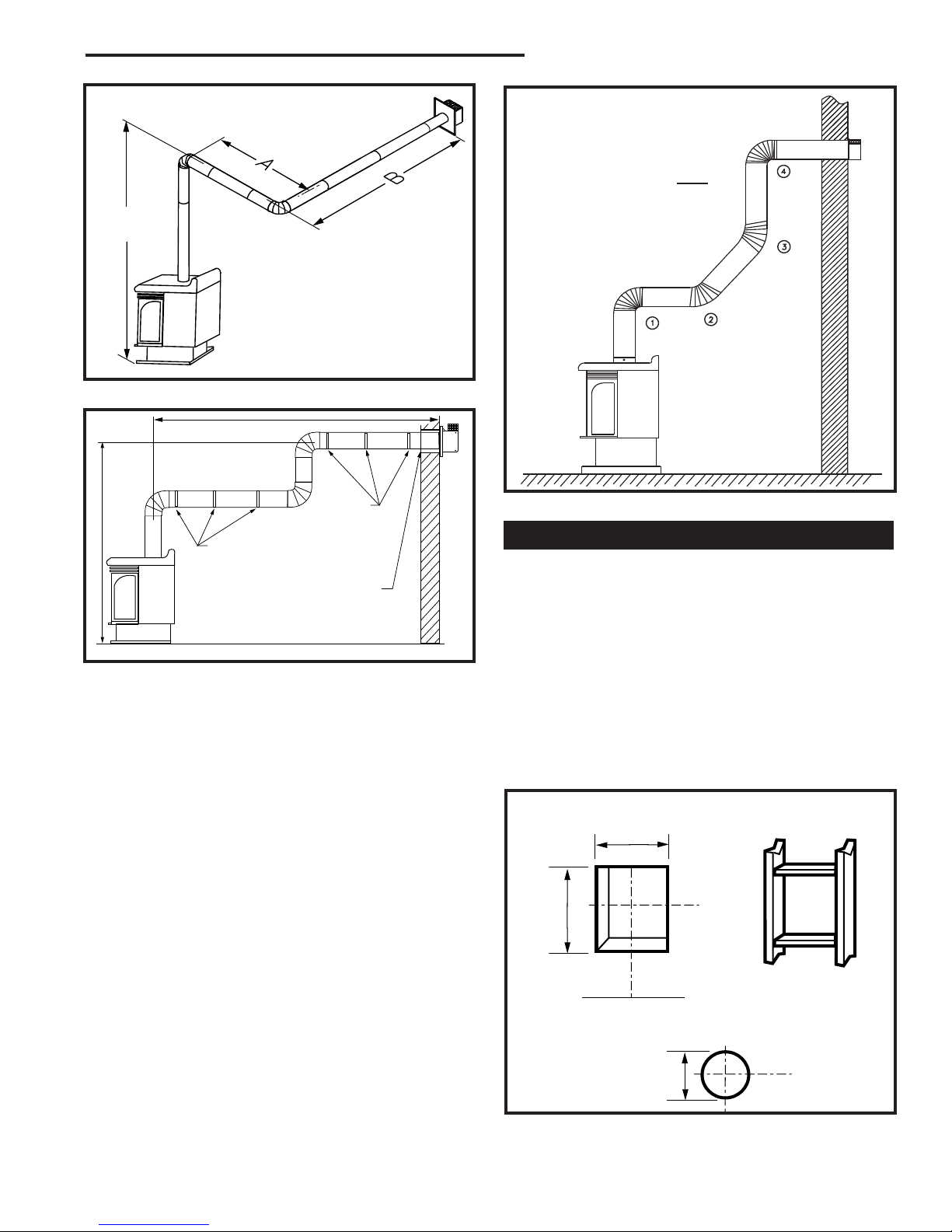
7.5ʼ
(2286 mm)
20ʼ
(6 m)
7.5ʼ (2. m)
Example:
Elbow 1 = 90°
Elbow = 45°
Elbow 3 = 45°
Elbow 4 = 90°
Total angular variation = 70°
A + B =17’ (5. m) Max.
FP1496
Fig. 10 90° elbow used in horizontal vent run.
Pipe Straps
Every 3’ (914 mm)
Pipe Straps Every 3’
(914 mm)
Fig. 11 90° elbow used to increase height.
Firestop / Zero
Clearance Sleeve
FP1497
Example: According to the chart the maximum
horizontal vent length is 0’ (6 m). However, if a 90°
elbow is used in the horizontal vent, maximum horizontal vent length is reduced to 17’ (5. m). In Figure
9, the total of Dim. A and Dim. B must not exceed 17’
(5. m).
• The maximum number of 45° elbows permitted per
installation is six (6). These elbows can be installed in
either the vertical or horizontal run.
• For each 45° elbow installed in the horizontal run, the
length of the horizontal run MUST be reduced by 18”
(457 mm). This does not apply if the 45° elbows are
installed on the vertical part of the vent system.
• The maximum number of elbow degrees in a system is
70°. (Fig. 1)
1 + + 3 + 4 = 70°
FP139
Fig. 12 Maximum elbow usage.
Vertical Sidewall Installations
STEP 1
Locate vent opening on the wall. It may be necessary to
rst position the stove and measure to obtain hole location. Depending on whether the wall is combustible or
noncombustible, cut opening to size. (Fig. 13)
For combustible walls rst frame in opening.
Combustible Walls: (Fig. 13) Cut a 9³⁄₈”H x 9³⁄₈”W (40
x 40 mm) hole through the exterior wall and frame as
shown.
Noncombustible Walls: (Fig. 13) Hole opening must be
7¹⁄₂” (190 mm) in diameter.
Vent Opening for Combustible Wall
9³⁄₈”
(40mm)
Framing
9³⁄₈”
(40mm)
Stove Hearth
Opening for Noncombustible Wall
Detail
10003550
7¹⁄₂”
(190mm)
VO584-100
Fig. 13 Locate vent opening on wall.
11
 Loading...