

Vermont Castings RFSDV22, RFSDV32, RFSDV42 Homeowner's Installation And Operating Manual
INSTALLER/ CONSUMER
SAFETY INFORMATION
PLEASE READ THIS MANUAL
BEFORE INSTALLING AND
USING APPLIANCE
WARNING!
IF THE INFORMATION IN
THIS MANUAL IS NOT
FOLLOWED EXACTLY, A FIRE
OR EXPLOSION MAY RESULT
CAUSING PROPERTY
DAMAGE, PERSONAL INJURY
OR LOSS OF LIFE.
Freestanding
Direct Vent Fireplaces
Models: RFSDV22,
FOR YOUR SAFETY
Installation and service must
be performed by a qualified
installer, service agency or the
gas supplier.
WHAT TO DO IF YOU SMELL
GAS:
• Do not try to light any
appliance.
• Do not touch any electric
switch; do not use any phone
in your building.
• Immediately call your gas
supplier from your neighbor's
phone. Follow the gas
suppliers instructions.
• If you cannot reach your gas
supplier call the fire
department.
DO NOT STORE
OR USE GASOLINE OR
OTHER FLAMMABLE VAPORS
AND LIQUIDS IN THE VICINITY
OF THIS OR ANY OTHER
APPLIANCE.
RFSDV32, RFSDV42
Homeowner’s Installation and
Operating Manual
I
S
G
E
N
D
C
E
D
R
E
I
T
I
F
CFM Specialty Home Products
410 Admiral Blvd. • Mississauga, Ontario, Canada L5T 2N6 • 905-670-7777
www.majesticproducts.com • www.vermontcastings.com
CERTIFIED
INSTALLER: DO NOT DISCARD THIS MANUAL - LEAVE FOR HOMEOWNER
10001028 7/04 Rev. 2

RFSDV22/32/42 Freestanding Direct Vent Fireplace
Table of Contents
PLEASE READ THE INSTALLATION & OPERATING INSTRUCTIONS BEFORE USING APPLIANCE.
Thank you and congratulations on your purchase of a CFM Specialty Home Products fireplace
IMPORTANT: Read all instructions and warnings carefully before starting installation. Failure to follow these instruc-
tions may result in a possible fire hazard and will void the warranty.
Installation Instructions
Important Curing/Burn Information.....................................................................................3
Locating the Fireplace........................................................................................................3
Fireplace Dimensions.........................................................................................................4
Clearance to Combustibles ................................................................................................5
Gas Specifications .............................................................................................................5
Gas Inlet & Manifold Pressures..........................................................................................5
High Elevations ..................................................................................................................5
Preparation.........................................................................................................................5
Gas Line Installation...........................................................................................................5
Installation of Remote Switch for RN/RP gas valve ...........................................................6
General Venting Information
General Venting Information - Termination Location .........................................................7
Termination Clearances .....................................................................................................8
General Information on Assembling Vent Pipes ................................................................8
Twist Lock Pipes ................................................................................................................8
How to use the Vent Graph................................................................................................9
Vertical Sidewall Applications ............................................................................................9
Vertical Sidewall Installation.............................................................................................11
Below Grade Installations (Snorkel).................................................................................12
Vertical Through-the-Roof Applications & Installation......................................................13
Twist Lock Venting Components......................................................................................15
Operating Instructions
Glass Information .............................................................................................................16
Louvre Removal ...............................................................................................................16
Trim Removal...................................................................................................................16
Glass Removal.................................................................................................................16
Glass Cleaning.................................................................................................................17
Installation of Logs & Burner Lava Rock Material ............................................................17
Ceramic Refractory ..........................................................................................................18
Flame Adjustment ............................................................................................................18
Temperature Adjustment..................................................................................................18
Flame Characteristics ......................................................................................................19
Lighting Instructions .........................................................................................................20
Troubleshooting ...............................................................................................................21
Maintenance ............................................................................................................................24
Replacement ............................................................................................................................25
Accessories ............................................................................................................................28
Mobile Home Instructions ...........................................................................................................29
Warranty ............................................................................................................................30
2
10001028
RFSDV22/32/42 Freestanding Direct Vent Fireplace
Installation and Operating Instructions
This gas fireplace should be installed by a qualified installer in
accordance with local building codes and with current CSAB149.1 Installation codes for Gas Burning Fireplaces and
Equipment and CAN/CSA Z 240.4 Canada.
FOR U.S.A Installations follow local codes and/or the current
National Fuel Gas Code. ANSI Z223.1/NFPA 54.
FOR SAFE INSTALLATION AND OPERATION PLEASE NOTE
THE FOLLOWING:
1 . This fireplace gives off high temperatures and should be
located out of high traffic areas and away from furniture
and draperies.
2. Children and adults should be alerted to the hazards of the
high surface temperatures of this fireplace and should stay
away to avoid burns or ignition of clothing.
3. Children should be carefully supervised when they are in
the same room as your fireplace.
4. Under no circumstances should this fireplace be
modified.Parts removed for servicing should be replaced
prior to operating the fireplace again.
5. Installation and any repairs to this fireplace should be
carried out by a qualified service person. A professional
service person should be contacted to inspect this fireplace
annually.Make it a practice to have all of your gas fireplaces checked annually. More frequent cleaning may be
required due to excess lint and dust from carpeting,
bedding material, etc.
6. Control compartments, burners and air passages in this
fireplace should be kept clean and free of dust and lint.
Make sure that the gas valve and pilot light are turned off
before you attempt to clean this fireplace.
7, The venting system(chimney) of this fireplace should be
checked at least once a year and if needed your venting
system should be cleaned.
8. Keep the area around your fireplace clear of combustible
materials, gasoline and other flammable vapour and
liquids. This fireplace should not be used as a drying rack
for clothing,nor should Christmas stockings or decorations
be hung in the area of it.
9. Under no circumstances should any solid fuels
(wood,coal,paper or cardboard etc.)be used in this fireplace.
10.The flow of combustion and ventilation air must not be
obstructed in any way.
11.When the fireplace is installed directly on carpeting, vinyl
tile or any combustible material other than wood, the
fireplace must be installed on a metal or wood panel
extending the full width and depth of the fireplace.
12.This fireplace requires adequate ventilation and
combustion air to operate properly.
13.This fireplace must not be connected to a chimney flue
serving a separate solid fuel burning fireplace.
IMPORTANT:
PLEASE REVIEW THE FOLLOWING CAREFULLY
Remove any plastic from trim parts before turning
the fireplace ON.
It is normal for fireplaces fabricated of steel to give
off some expansion and/or contraction noises during
the start up or cool down cycle. Similar noises are
found with your furnace heat exchanger or car
engine. It is not unusual for your gas fireplace to
give off some odor the first time it is burned. This is
due to the curing of the paint and any undetected oil
from the manufacturing process.
Please ensure that your room is well ventilated -
open all windows.
It is recommended that you burn your fireplace for a
least six (6) hours the first time you use it. If optional
fan kit has been installed, place fan in the "OFF"
position during this time.
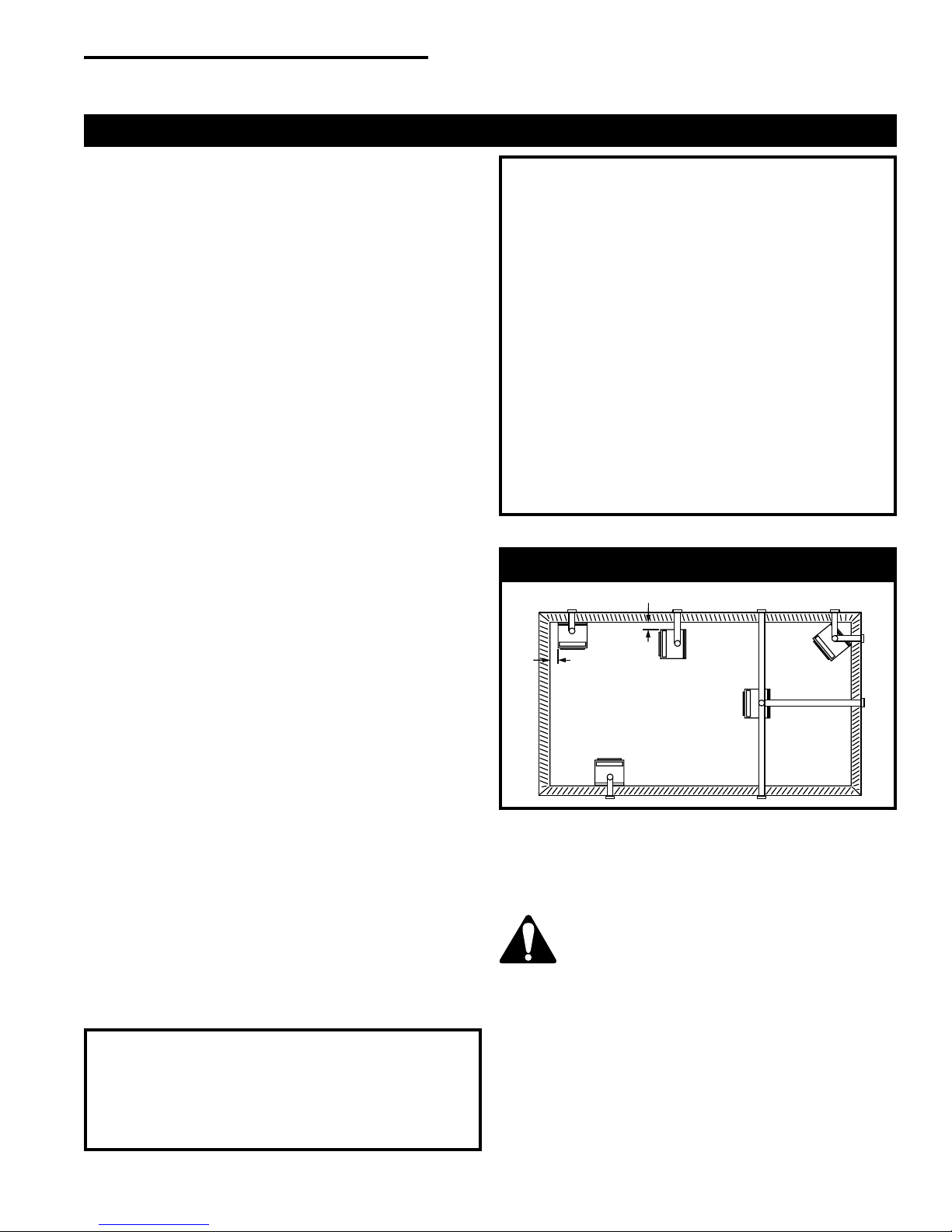
Locating the Fireplace
12 in. (305mm)
A
12 in.
(305mm)
B
C
E
Fig. 1 Locating gas fireplace.
A) *Flat on wall corner B) *Room divider
C) Island D) Cross corner
E) Flat on wall
* A & B must maintain a 12" (305mm) clearance between the wall and
side glass of fireplace.
There is a minimum vertical rise required for the venting
which varies depending on the application. The maximum
horizontal run also has restrictions. Become familiar with
the venting instructions starting on page 7, before starting
the installation.
D
Proposition 65 Warning: Fuels used in gas,
woodburning or oil fired appliances, and the products
of combustion of such fuels, contain chemicals known
to the State of California to cause cancer, birth defects
and other reproductive harm.
California Health & Safety Code Sec. 25249.6
10001028
3
RFSDV22/32/42 Freestanding Direct Vent Fireplace
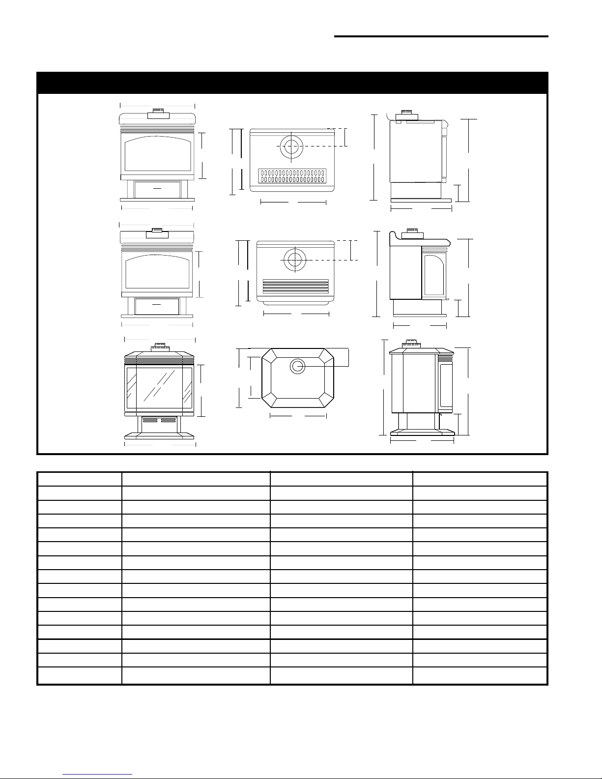
Fireplace Dimensions
A
K
C
D
E
B
A
C
B
A
C
D
E
D
M
F
RFSDV22
F
RFSDV32
N
RFSDV42
B
G
H
K
G
H
K
L
H
I
J
I
J
I
J
Fig. 2 Fireplace specifications.
Ref. RFSDV22 RFSDV32 RFSDV42
A 26" (660mm) 25" (635mm) 28¹⁄₄" (717mm)
B 26" (660mm) 24¹⁄₈" (613mm) 28¹⁄₄" (717mm)
C15¹⁄₄" (387mm) 16" (406mm) 17⁷⁄₈" (454mm)
D19¹⁄₄" (488mm) 20" (508mm) 22³⁄₄" (578mm)
E18⁵⁄₈" (473mm) 19" (483mm) -- --
F 21" (533mm) 21" (533mm) -- -G31¹⁄₂" (800mm) 31³⁄₄" (806mm) -- --
H17³⁄₄" (451mm) 17³⁄₄" (451mm) 22³⁄₄" (578mm)
I29⁵⁄₈" (752mm) 29⁵⁄₈" (752mm) 33⁵⁄₈" (854mm)
J9⁵⁄₈" (244mm) 9" (229mm) 10⁵⁄₈" (270mm)
K6¹⁄₂" (165mm) 6¹⁄₂" (165mm) 7" (178mm)
L-------- 36³⁄₈" (924mm)
M-------- 14³⁄₁₆" (360mm)
N-------- 17³⁄₈" (441mm)
4
10001028
RFSDV22/32/42 Freestanding Direct Vent Fireplace
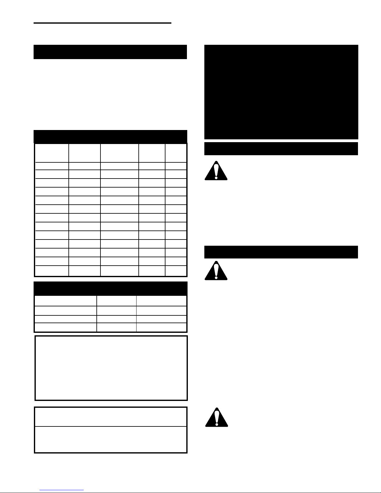
Clearance to Combustibles
Adequate clearances as listed below must be
maintained for servicing and proper operation:
Back ...............................................................0" (0mm)
Side .......................................................... 12" (305mm)
Floor ............................................................... 0" (0mm)
Top ........................................................... 36" (914mm)
Corner ....................................0" to Back Edges (0mm)
Vent Pipe......................................................1" (25mm)
Gas Specifications
Max. Min.
Input Input
Model Fuel Gas Control B.T.U.H B.T.U.H.
RFSDV22RN Natural Gas Millivolt Hi/Lo 30,000 21,000
RFSDV22RP Propane Gas Millivolt Hi/Lo 30,000 22,500
RFSDV22TN Natural Gas Thermostatic 30,000 21,000
RFSDV22TP Propane Gas Thermostatic 30,000 22,500
RFSDV32RN Natural Gas Millivolt Hi/Lo 30,000 21,000
RFSDV32RP Propane Gas Millivolt Hi/Lo 30,000 22,500
RFSDV32TN Natural Gas Thermostatic 30,000 21,000
RFSDV32TP Propane Gas Thermostatic 30,000 22,500
RFSDV32RMH Nat/Prop Millivolt Hi/Lo 30,000 N/A
RFSDV42RN Natural Gas Millivolt Hi/Lo 40,000 28,000
RFSDV42RP Propane Gas Millivolt Hi/Lo 37,000 27,750
RFSDV42TN Natural Gas Thermostatic 40,000 28,000
RFSDV42TP Propane Gas Thermostatic 37,000 27,750
Gas Inlet and Manifold Pressures
Natural LP (Propane)
Inlet Minimum 4.5" w.c. 11.0" w.c.
Inlet Maximum 14.0" w.c. 14.0" w.c.
Manifold Pressure 3.5" w.c. 10.0" w.c.
This appliance may be installed in an aftermarket
permanently located, manufactured (mobile) home,
where not prohibited by local codes.
This appliance is only for use with the type of gas
indicated on the rating plate. This appliance is not
convertible for use with other gases, unless a
certified kit is available and used.
RFSDV22 / RFSDV32 / RFSDV42
Certified To
ANSI.Z21.88-2002 / CSA 2.33-2002
Vented Gas Fireplace Heaters
High Elevations
Input ratings are shown in BTU per hour and
are certified without deration for elevations up
to 4,500 ft. (1,370 m) above sea level. For
elevations above 4,500 ft. (1,370 m) in USA,
installations must be in accordance with the
current ANSI Z223.1 and/ or local codes having
jurisdiction.
In Canada, please consult provincial and/ or
local authorities having jurisdiction for
installations at elevations above 4,500 ft.
(1,370 m).
Preparation
The use of wall paper adjacent to this
fireplace is not recommended, as the
high temperatures given off by this
fireplace may adversely effect the binders
in the adhesive used to apply the wallpaper.
Before beginning, remove the glass door from the
fireplace. Also check to make sure there is no hidden
damage to the fireplace. Take a minute and plan out
the gas, vent and electrical supply. See Glass Removal
Section.
Gas Line Installation
When purging gas line, the front glass
must be removed.
The gas pipeline can be brought in through the rear of
the fireplace as well as the bottom. Knockouts are
provided on the bottom behind the valve to allow for
the gas pipe installation and testing of any gas connection. It is most convenient to bring the gas line in
from the rear right side of the valve, as this allows
fan installation or removal without disconnecting
the gas line.
The gas line connection can be made with properly
tinned 3/8" copper tubing, 3/8" rigid pipe or an
approved flex connector. Since some
municipalities have some additional local codes, it
is always best to consult your local authority and
the CSA- B149.1 installation code.
For U.S. Installations consult the current National
Fuel Gas Code, ANSI Z223.1.
Always check for gas leaks with a mild
soap and water solution. Do not use an
open flame for leak testing.
The gas control is equipped with a captured screw type
pressure test point, therefore it is not necessary to
provide a 1/8" test point up stream of the control.
10001028
5
RFSDV22/32/42 Freestanding Direct Vent Fireplace
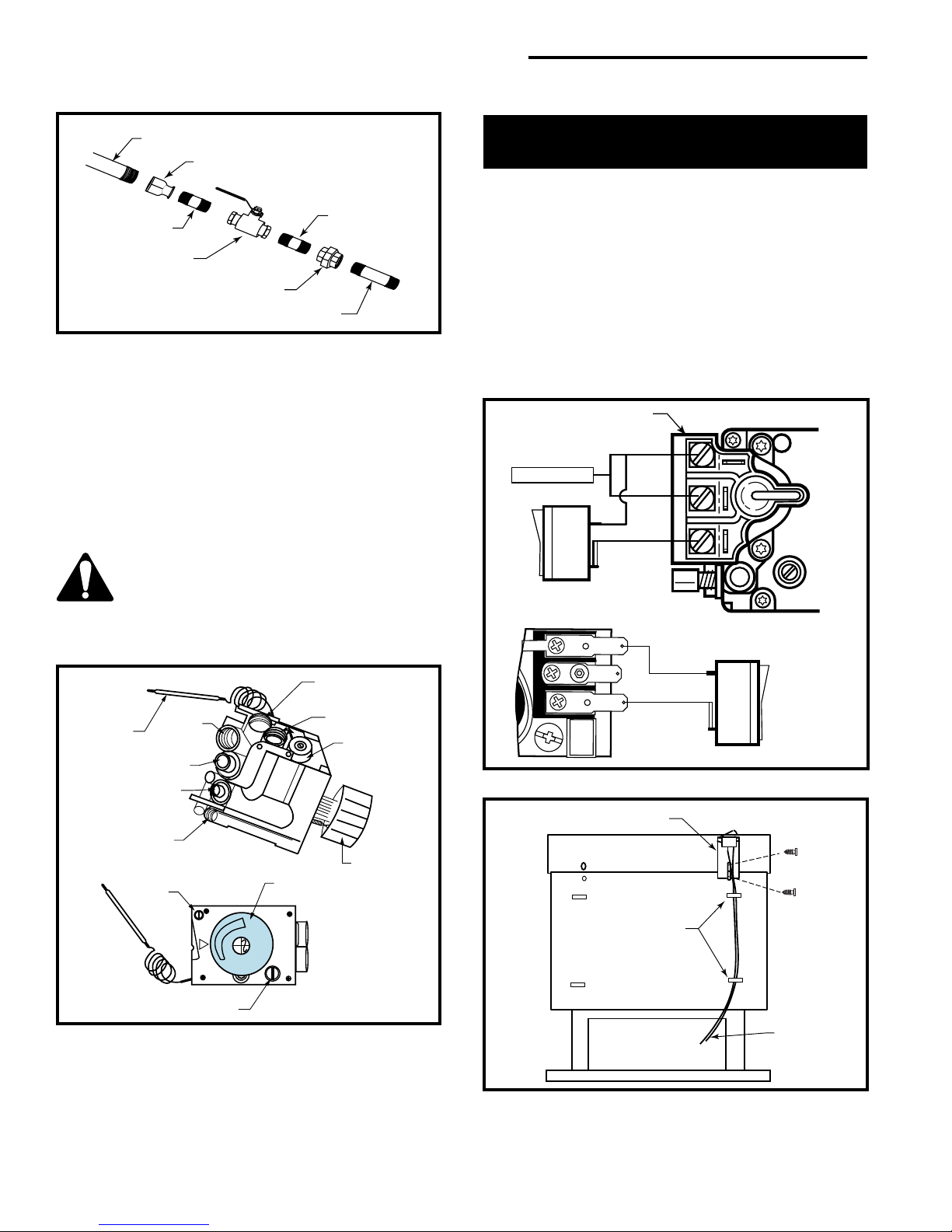
1/2" Gas Supply
1/2" x 3/8" Reducer
3/8" Nipple
3/8" x 3/8" Shut Off
Valve
3/8" Union
3/8" Nipple
3/8" Nipple
CFM106
Fig. 3 Typical gas line installation.
When using copper or flex connector use only approved fittings. Always provide a union when using
back iron pipe so that gas line can be easily disconnected for burner or fan servicing. (Fig. 3) Refer to gas
specification chart for pressure details and ratings.
The fireplace valve must not be subjected to any test
pressures exceeding 1/2 psi. Isolate or disconnect this
or any other gas appliance control from the gas line
when pressure testing.
Do not use this fireplace if any part of
this fireplace has been under water.
Immediately call a qualified service
technician to inspect the heater and to
replace any part control which has been
under water.
Manifold Gas
Outlet
Brass Plug
Control Knob
Pressure
Regulator
Control Knob
Thermostat
Bulb
Gas Inlet
Thermocouple
Inlet
Pilot Tube Entry
Pilot Adjustment
Screw
Brass
Plug
Installation of Remote
Switch for RN/RP Gas Valve
Install on/off switch assembly on either the rear right or
left side of the Fireplace.
1. Remove the screw at the back of the cabinet top
either on the left or the right side of the fireplace.
2. Position switch assembly onto the back of the
fireplace, then fasten two screws as shown in Figure
6.
3. Attach wiring under the clips on the rear casing (Fig.
6) and install wiring through the rear opening of the
fireplace before connecting to the valve as shown in
Figure 5.
SIT Valve
THTP
Thermopile
TH
TP
TPTH
Fig. 5 On/Off switch or millivolt thermostat.
ON/OFF Switch Assembly
TP
TH
P
I
L
T
O
Screw
(Through
existing
hole)
FP382a
FP1218a
I
H
it
OFF
PILOT
LO
Minimum Rate Screw
(Nonadjustable)
Fig. 4 On fireplaces equipped with Eurosit 630 gas valves
there are brass plugs in two of the holes. These plugs are
not to be removed. The gas inlet hole has a plastic cap in it.
Remove the plastic cap and connect your gas supply line at
this point.
6
HV118
Clips
Wiring for
Milli-Volt
Gas Valves
FP1331
Fig. 6 Secure wiring under clips on the rear casing.
10001028
RFSDV22/32/42 Freestanding Direct Vent Fireplace
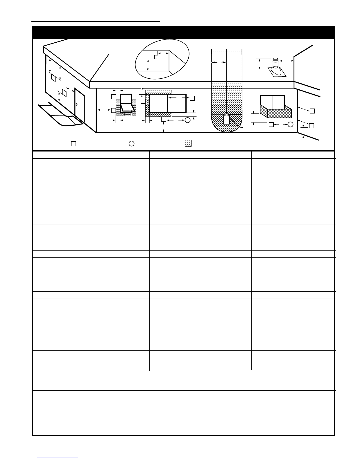
General Venting Information - Termination Location
INSIDE
CORNER DETAIL
G
V
D
E
V
A
H
N
N
CFM145a
B
V
L
VENT TERMINATION AIR SUPPLY INLET
V
C
Fixed
Fixed
V
Closed
Closed
F
Operable
V
B
B
V
Operable
B
X
B
Fixed
Closed
V
A
V
B
X
J
AREA WHERE TERMINAL IS NOT PERMITTED
Canadian Installations
G
V
M
I
1
K
V
US Installations
G
X
V
A
2
A = Clearance above grade, veranda, porch, 12” (30cm) 12” (30cm)
deck, or balcony
B = Clearance to window or door that may be 6” (15cm) for appliances 6” (15cm) for appliances
opened < 10,000Btuh (3kW), 12” (30cm) < 10,000 Btuh (3kW), 9”
for appliances > 10,000 Btuh (3kW) and (23cm) for appliances > 10,000
< 100,000 Btuh (30kW), 36” (91cm) Btuh (3kW) and < 50,000 Btuh
for appliances > 100,000 Btuh (30kW) (15kW), 12” (30cm) for
appliances > 50,000 Btuh (15kW)
C = Clearance to permanently closed window 12” (305mm) recommended to 12” (305mm) recommended to
prevent window condensation prevent window condensation
D = Vertical clearance to ventilated soffit located
above the terminal within a horizontal 18” (458mm) 18” (458mm)
distance of 2 feet (610mm) from the center
line of the terminal
E = Clearance to unventilated soffit 12” (305mm) 12” (305mm)
F = Clearance to outside corner see next page see next page
G = Clearance to inside corner (see next page) see next page see next page
H = Clearance to each inside of center line 3’ (914mm) within a height of 15’ (4.6m) 3’ (914mm) within a height of 15’
extended above meter/regulator assembly above the meter/regulator assembly (4.6m) above the meter/regulator
assy
I = Clearance to service regulator vent outlet 3’ (914mm) 3’ (914mm)
J = Clearance to nonmechanical air supply inlet 6” (15cm) for appliances < 10,000 6” (15cm) for appliances
to building or the combustion air inlet to any Btuh (3kW), 12” (30cm) for < 10,000 Btuh (3kW), 9”
other appliances appliances > 10,000 Btuh (3kW) and < (23cm) for appliances > 10,000
100,000 Btuh (30kW), 36” (91cm) Btuh (3kW) and < 50,000 Btuh
for appliances > 100,000 Btuh (30kW) (15kW), 12” (30cm) for
appliances > 50,000 Btuh (15kW)
K = Clearance to a mechanical air supply inlet 6’ (1.83m) 3’ (91cm) above if within 10’
(3m) horizontally
L = Clearance above paved sidewalk or paved 7’ (2.13m)† 7’ (2.13m)†
driveway located on public property
M = Clearance under veranda, porch, deck or 12” (30cm)‡ 12” (30cm)‡
balcony
N = Clearance above a roof shall extend a minimum of 24” (610mm) above the highest point when it passes through the roof
surface, and any other obstruction within a horizontal distance of 18” (450mm).
1 In accordance with the current CSA-B149 Installation Codes
2 In accordance with the current ANSI Z223.1/NFPA 54 National Fuel Gas Codes
† A vent shall not terminate directly above a sidewalk or paved driveway which is located between two single family dwellings and
serves both dwellings
‡ only permitted if veranda, porch, deck or balcony is fully open on a minimum 2 sides beneath the floor:
NOTE: 1. Local codes or regulations may require different clearances.
2. The special venting system used on Direct Vent Fireplaces are certified as part of the appliance, with clearances tested and
approved by the listing agency.
10001028
7
RFSDV22/32/42 Freestanding Direct Vent Fireplace
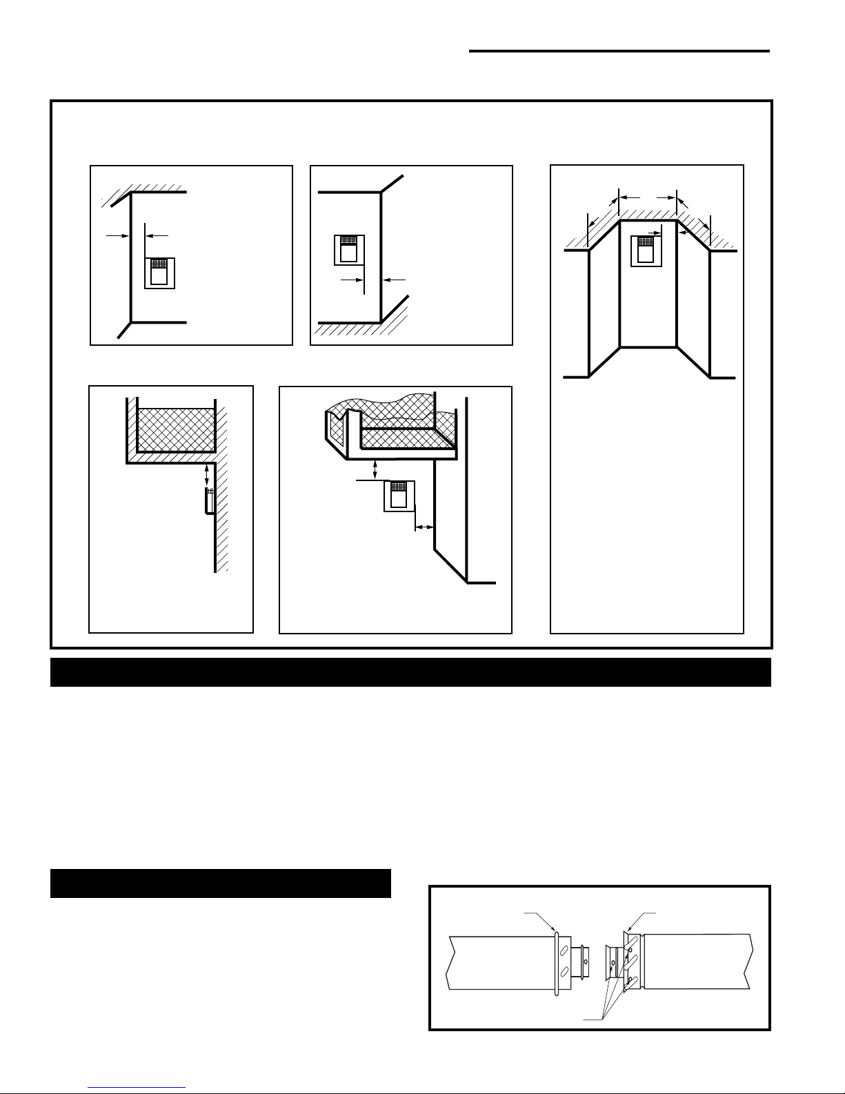
Termination Clearances
Termination clearances for buildings with combustible and noncombustible exteriors.
Inside Corner
Outside Corner
Recessed Location
A
V
Balcony with no side wall
G =
Combustible &
Noncombustible
12"(305mm)
A =
Combustible
6"(152mm)
Noncombustible
2"(50mm)
G
V
B =
Combustible
6"(152mm)
V
Noncombustible
2"(50mm)
B
Balcony with perpendicular side wall
H
V
Combustible &
Noncombustible
H = 24"(610mm)
J = 20"(508mm)
J
D
C
C
E
V
C = Maximum depth of 48"
(1219mm) for recessed
location.
D = Minimum width for back wall
of a recessed location.
Combustible 38"(965mm)
Noncombustible 24"(610mm)
E = Clearance from corner in
recessed location.
Combustible 6"(152mm)
Noncombustible 2"(50mm)
584-15
General Information Assembling Vent Pipes
Canadian Installations:
The venting system must be installed in accordance
with the current CSA-B149.1 installation code.
U.S.A. Installations:
The venting system must conform with local codes
and/or the current National Fuel Gas Code, ANSI
Z223.1/NFPA 54.
Only venting components manufactured by CFM
Corporation may be used.IST LOCK
Twist Lock PIpes
When using CFM Corporation twist lock pipe it is not
necessary to use sealant at the twist lock joints.
The only areas of the venting that need to be sealed
with high temperature silicone sealant are the collars
on the fireplace and termination, and the sliding joint of
any telescopic vent pipes used in the system.
8
To join the twist lock pipes together, simply align the
beads of the male end with the grooves of the female
end, then while bringing the pipes together, twist the
pipe until the flange on the female end contacts the
external flange on the male end.
It is recommended that you secure the joints with 3
sheet metal screws, however this is not mandatory with
twist lock pipe.
To make it easier to assemble the joints we suggest
putting a lubricant (Vaseline or similar) on the male end
of the twist lock pipe.
Male End
Screw Holes
Fig. 7 Twist-lock pipe joints.
Female End
TWL100
10001028
RFSDV22/32/42 Freestanding Direct Vent Fireplace
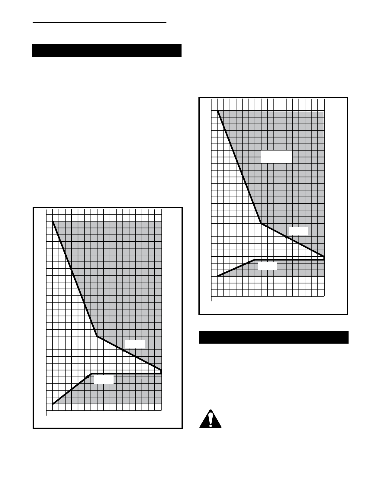
How to Use the Vent Graph
1. Determine the height of the centre of the horizontal
vent pipe exiting through the outer wall. Using this
dimension on the Sidewall Vent Graph (Fig. 8 or 9),
locate the point it intersects with the slanted graph
line.
2. From the point of this intersection, draw a vertical
line to the bottom of the graph.
3. Select the indicated dimension, and position the fireplace in accordance with same.
EXAMPLE A:
If the vertical dimension from the floor of the fireplace
is 11' (335cm) the horizontal run to the face of the
outer wall must not exceed 14' (427cm).
EXAMPLE B:
If the vertical dimension from the floor of the fireplace
is 7' (214cm), the horizontal run to the face of the outer
wall must not exceed 8.5' (259cm).
For RFSDV22 & RFSDV32
30
29
28
27
26
25
24
23
22
21
20
19
18
17
16
15
14
13
12
11
10
9
8
7
6
5
4
3
3 4 5 6 7 8 9 10 11 12 13 14 15 16 17 18 19 20
eg: B
eg: A
Horizontal Dimension
Fig. 8 Sidewall venting graph for use with RFSDV22/32.
Vertical Dimension from the Floor of the Fireplace to the
Center of the Horizontal Vent Pipe
EXAMPLE C: (only RFSDV42)
If the vertical dimension from the floor of the fireplace is
7' (214mm), the horizontal run to the face of the outer
wall must not exceed 8' (244cm).
Refer to Page 12 for venting requirements for
snorkels.
For RFSDV42
30
29
28
27
26
25
24
23
22
21
20
19
18
17
16
15
14
13
12
11
10
9
8
7
6
5
4
3
3 4 5 6 7 8 9 10 11 12 13 14 15 16 17 18 19 20
RFSDV42
ONL Y
eg: A
eg: C
Vertical Dimension from the Floor of the Fireplace
to the Center of the Horizontal Vent Pipe
Horizontal Dimension
Fig. 9 Sidewall venting graph for use with RFSDV42 only.
Vertical Sidewall Applications
Since it is very important that the venting system
maintain its balance between the combustion air
intake and the flue gas exhaust, certain limitations
as to vent configurations apply and must be
strictly adhered to.
The graph showing the relationship between vertical
and horizontal side wall venting will help to determine
the various lengths allowable. (Fig. 8 or 9)
Minimum clearance between vent pipes
and combustible materials is 1" (25mm)
on top, bottom and sides unless otherwise noted.
10001028
9
 Loading...