

Vermont Castings RADVT(CS)CBSB, RADVTCSBSSB, RADVTCSBDSB, RADVTCSBMSB, RADVTCBSB Installation And Operating Instructions Manual
...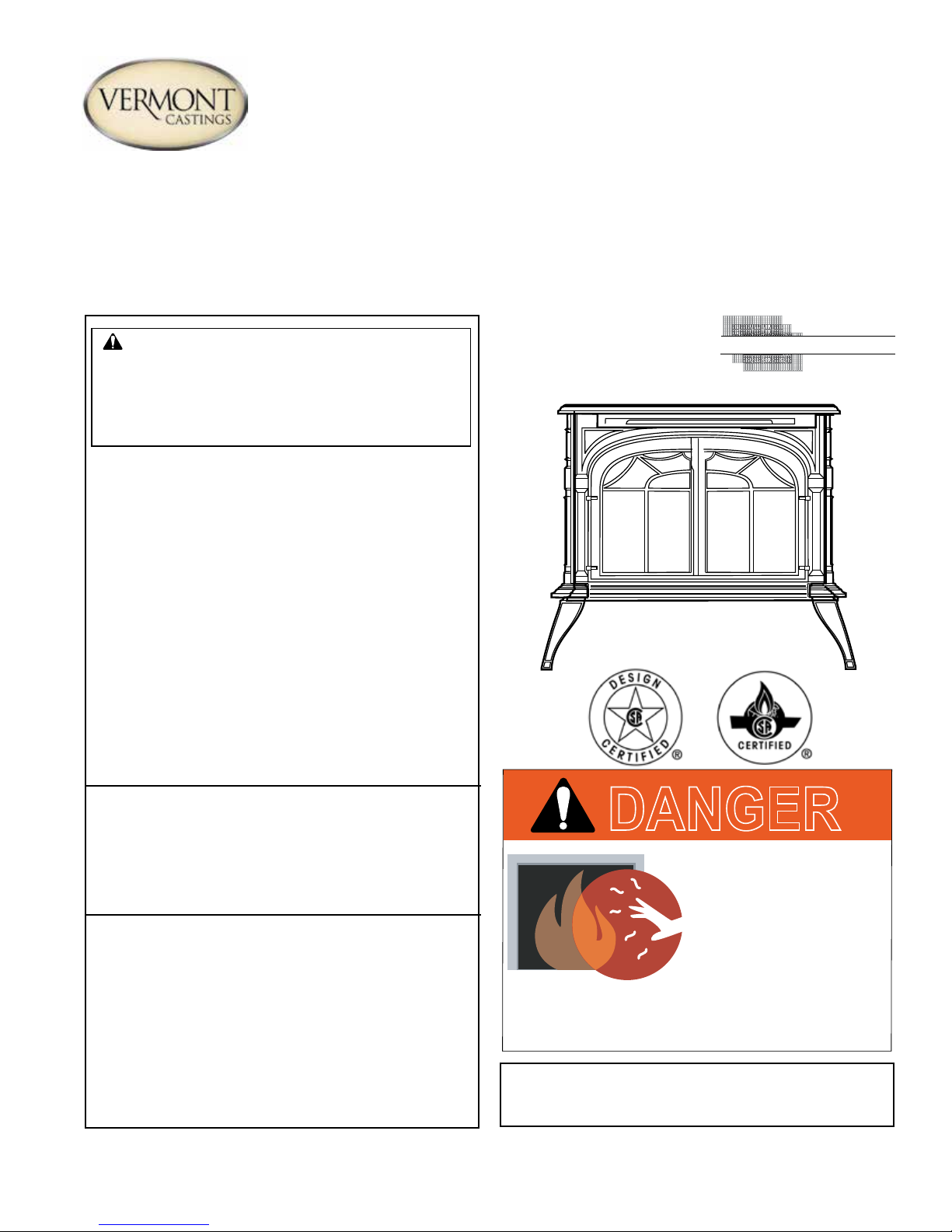
RADVT Series Radiance® Direct Vent Gas Heater
S
Installation and Operating Instructions
Models: RADVT(CS)CBSB, RADVT(CS)BSSB, RADVT(CS)BDSB, RADVT(CS)BMSB
WARNING:
FIRE OR EXPLOSION HAZARD
Failure to follow safety warnings exactly
could result in serious injury, death or
property damage.
• Do not store or use gasoline or other
ammable vapors and liquids in the
vicinity of this or any other appliance.
• WHAT TO DO IF YOU SMELL GAS
– Do not try to light any appliance.
– Do not touch any electrical switch; do
not use any phone in your building.
– Leave the building immediately.
– Immediately call your gas supplier from
a neighbor's phone. Follow the gas
supplier's instructions.
– If you cannot reach your gas supplier,
call the re department.
• Installation and service must be performed
by a qualied installer, service agency or
the gas supplier.
WARNING: Improper installation, adjustment,
alteration, service or maintenance can cause
injury or property damage. Refer to this manual.
For assistance or additional information consult
a qualified installer, service agency or the
gas supplier.
This appliance may be installed in an aftermarket,*
permanently located, manufactured home (USA
only) or mobile home, where not prohibited by
local codes.
This appliance is for use only with the type of gas
indicated on the rating plate. This appliance is
not convertible for use with other gases, unless
a certied kit is used.
* Aftermarket: Completion of sale, not for purpose of resale, from
the manufacturer.
CERTIFIED
AFETY BARRIER
DANGER
HOT GLASS WILL
CAUSE BURNS.
DO NOT TOUCH GLASS
UNTIL COOLED.
NEVER ALLOW CHILDREN
TO TOUCH GLASS.
A barrier designed to reduce the risk of burns from
the hot viewing glass is provided with this
appliance and shall be installed.
INSTALLER: Leave this manual with the appliance.
CONSUMER: Retain this manual for
future reference.
20306759 12/14 Rev. 1

Radiance® Direct Vent Gas Heater
Table of Contents
PLEASE READ THE INSTALLATION & OPERATING INSTRUCTIONS BEFORE USING APPLIANCE.
Thank you and congratulations on your purchase of a Vermont Castings stove.
IMPORTANT: Read all instructions and warnings carefully before starting installation. Failure to follow these instructions
may result in a possible re hazard and will void the warranty.
Installation & General Information .............................3
Massachusetts Residents Only ........................................4
Stove Dimensions ............................................................5
Installation Requirements .................................................6
Locating the Stove............................................................6
Clearance Requirements .................................................6
Parallel Installation ..........................................................7
Corner Installation ...........................................................7
Wall and Ceiling Clearances ...........................................7
Hearth Requirements ......................................................7
Gas Specications ...........................................................8
Gas Inlet and Manifold Pressures ...................................8
High Elevations ...............................................................8
Horizontal Termination .....................................................8
Vertical Termination .........................................................9
Restrictor Plate Adjustment for Extended Pipe Runs .......9
Vent Termination Clearances ........................................10
General Venting Information - Termination Location .....11
Termination Clearances .................................................12
Venting Requirements and Options ...............................13
Assembly Procedures ...............................................15
Tools Required ..............................................................15
Parts Bag Contents .......................................................15
Unpack and Assemble Legs ...........................................15
Install Optional Fan .......................................................16
Venting System Assembly - Direct Vent ........................17
Install Vent Adapter Pipe ...............................................17
Side Wall Termination Assembly ...................................18
Vent Termination Below Grade ......................................20
Vertical (Through the Roof) Vent Assembly ...................20
Selkirk Direct-Temp Metalbestos Direct Vent System ....21
Install Log Set.................................................................26
Connect Gas Supply Line ..............................................28
Burner Information .........................................................28
Install ON/OFF Switch ...................................................29
Thermostat Connection (Optional) ................................29
Receiver Installation - RADVTCS Series .......................29
Install the Safety Barrier .................................................30
Install the Mesh and Grille .............................................30
Operation ....................................................................31
Your First Fire ................................................................ 31
Pilot and Burner Inspection ...........................................31
Flame & Temperature Adjustment .................................31
Flame Characteristics ....................................................31
Lighting and Operating Instructions ...............................32
Troubleshooting - SIT NOVA 820 (RADVT Series) .......33
Instructions for RCSITEA ..............................................34
Troubleshooting RCSITEA .............................................38
Fuel Conversion Instructions .........................................39
Maintenance ...............................................................43
Annual System Inspection .............................................43
Logset and Burner/Cleaning and Inspection .................43
Care of Cast Iron ...........................................................43
Cleaning the Glass ........................................................43
Glass Replacement .......................................................44
Gasket Replacement .....................................................44
Inspect the Vent System Annually ................................. 44
Check the Gas Flame Regularly ...................................44
Wiring Diagrams ............................................................44
Replacement Parts ...................................................45
Optional Accessories ............................................... 49
Warranty ....................................................................51
22
20306759

Installation & Operating Instructions
The Radiance Direct Vent Room Heater, Model Nos. RADVTCB,
RADVTEB, RADVTBS, RADVTBD, RADVTBM, RADVTCSCB,
RADVTCSEB, RADVTCSBS, RADVTCSBD, RADVTCSBM, is
a vented gas appliance listed to the ANSI Standard Z21.88-2009
and CSA 2.33-2009 for Vented Room Heaters, and CSA 2.17M91, Gas-Fired Appliances For Use at High Altitudes.
The installation of the Radiance Direct Vent Room Heater must
conform with local codes, or in the absence of local codes, with
National Fuel Gas Code, ANSI Z223.1/NFPA 54 — latest edition
and CSA B-149.1 Installation Code. (EXCEPTION: Do not derate this appliance for altitude. Maintain the manifold pressure
at 3.5 inches w.c. for Natural Gas and 10 inches w.c. for LP gas
at maximum input.)
This appliance is only for use with the type of gas indicated on the
rating plate. This appliance is not convertible for use with other
gases unless a certied kit is used.
Installation and replacement of gas piping, gas utilization
equipment or accessories, and repair and servicing of equipment shall be performed only by a qualied agency, preferably
NFI or WETT (Canada) certied. The term “qualied agency"
means any individual, rm, corporation, or company that
either in person or through a representative is engaged in
and is responsible for (a) installation or replacement of gas
piping, or (b), the connection, installation, repair, or servicing of equipment, who is experienced in such work, familiar
with all precautions required, and has complied with all the
requirements of the authority having jurisdiction.
The Radiance Direct Vent Room Heater should be inspected
before use and at least annually by a qualied service agency.
It is imperative that control compartments, burners, and circulating air passageways of the appliance be kept clean.
The Radiance Direct Vent Room Heater and its individual shut-off
valve must be disconnected from the gas supply piping during
any pressure testing of that system at test pressures in excess
of 1/2 psig (3.5 kPa).
The Radiance Direct Vent Room Heater must be isolated from the
gas supply piping system by closing its individual manual shutoff
valve during any pressure testing of the gas supply piping system
at test pressures equal to or less than 1/2 psig.
An accessible tap is located above the pilot/On-Off knob for
checking the inlet pressure.
‘Direct Vent’ describes a sealed combustion system in which incoming outside air for combustion and outgoing exhaust enter and
exit through two separate concentric passages within the same
sealed vent system. The system does not use room air to support
combustion. The Direct Vent system permits the gas appliance
to be vented directly to the outside atmosphere through the side
of the house or vertically through the roof. Conventional venting
systems (Natural Vent) take air from the room for combustion and
vent the exhaust vertically through the roof to the atmosphere.
This appliance is approved for bedroom installations in the U.S.
and Canada.
This appliance may be installed in an aftermarket* manufactured
(mobile) home, where not prohibited by state or local codes.
Radiance® Direct Vent Gas Heater
WARNING: Operation of this heater when not connected to a
properly installed and maintained venting system can result
in carbon monoxide (CO) poisoning and possible death.
The Radiance Direct Vent Room Heater, when installed, must
be electrically grounded in accordance with local codes or, in
the absence of local codes, with the National Electrical Code
ANSI/NFPA 70, (latest edition), or of the current Canadian Electrical Code C22.1.
Due to high temperatures this appliance should be located
out of trafc and away from furniture and draperies.
WARNING: This appliance is hot while in operation. Keep
children, clothing, and furniture away. Contact may cause
burns or ignition of combustible materials.
Children and adults should be alerted to the hazards of high
surface temperatures and should stay away to avoid burns
or clothing ignition.
Young children should be carefully supervised when they
are in the same room as the appliance. Toddlers, young
children and others may be susceptible to accidental contact
burns. A physical barrier is recommended if there are at risk
individuals in the house. To restrict access to a replace
or stove, install an adjustable safety gate to keep toddlers,
young children and other at risk individuals out of the room
and away from hot surfaces.
Clothing or other ammable materials should not be placed
on or near the appliance.
Any safety screen, glass or guard removed for servicing an appliance must be replaced prior to operating the appliance.
The appliance area must be kept clear and free from combustible materials, gasoline, and other ammable vapors
and liquids.
The ow of combustion and ventilation air must not be obstructed. The installation must include adequate accessibility
and clearance for servicing and proper operation.
WARNING: Do not operate the Room Heater with the glass
panel removed, cracked or broken. Replacement of the panel
should be done by a licensed or qualied service person.
Do not use this appliance if any part has been under water.
Immediately call a qualied service technician to inspect the
appliance and to replace any part of the control system and
any gas control which has been under water.
Do not burn wood, trash or any other material for which this
appliance was not designed. This appliance is designed to
burn either natural gas or propane only.
This gas appliance must not be connected to a chimney ue
serving a separate solid-fuel burning appliance.
CAUTION: Label all wires prior to disconnection when
servicing controls. Wiring errors can cause improper and
dangerous operation.
Verify proper operation after servicing.
Aftermarket: Completion of sale, nor for purpose of resale,
*
from the manufacturer.
20306759
3

Radiance® Direct Vent Gas Heater
Installation & Operating Instructions
Requirements for the Commonwealth of
Massachusetts
All gas tting and installation of this heater shall only be
done by a licensed gas tter or licensed plumber.
For all side wall horizontally vented gas fueled equipment
installed in every dwelling, building or structure used in whole
or in part for residential purposes, including those owned
or operated by the Commonwealth and where the side wall
exhaust vent termination is less than seven (7) feet above
nished grade in the area of the venting, including but not
limited to decks and porches, the following requirements
shall be satised:
Installation of Carbon Monoxide Detectors
At the time of installation of the side wall horizontal vented
gas fueled equipment, the installing plumber or gas tter
shall observe that a hard wired carbon monoxide detector
with an alarm is installed on each additional level of the
dwelling, building or structure served by the side wall
horizontal vented gas fueled equipment. It shall be the
responsibility of the property owner to secure the services
of qualied licensed professionals for the installation of
hard wired carbon monoxide detectors.
In the event that the side wall horizontally vented gas fueled
equipment is installed in a crawl space or an attic, the hard
wired carbon monoxide detector with alarm and battery
back-up may be installed on the next adjacent oor level.
In the event that the requirements of this subdivision can not
be met at the time of completion of installation, the owner
shall have a period of thirty (30) days to comply with the
above requirements; provided, however, that during said
thirty (30) day period, a battery operated carbon monoxide
detector with an alarm shall be installed.
Approved Carbon Monoxide Detectors
Each carbon monoxide detector as required in accordance
with the above provisions shall comply with NFPA 720 and
ANSI/UL 2034 listed and IAS certied.
Signage
A metal or plastic identication plate shall be permanently
mounted to the exterior of the building at a minimum height
of eight (8) feet above grade directly in line with the exhaust
vent terminal for the horizontally vented gas fueled heating
appliance or equipment. The sign shall read, in print size no
less than one-half (1/2) inch in size, “GAS VENT DIRECTLY
BELOW, KEEP CLEAR OF ALL OBSTRUCTIONS".
Inspection
The state or local gas inspector of the side wall horizontally
vented gas fueled equipment shall not approve the
installation unless, upon inspection, the inspector observes
carbon monoxide detectors and signage installed in
accordance with the provisions of 248 CMR 5.08(2)(a)1
through 4.
Exemptions
The following equipment is exempt from 248 CMR
5.08(2)(a)1 through 4:
• The equipment listed in Chapter 10 entitled “Equipment
Not Required To Be Vented" in the most current edition
of NFPA 54 as adopted by the Board; and
• Product Approved side wall horizontally vented gas fueled
equipment installed in a room or structure separate from
the dwelling, building or structure used in whole or in
part for residential purposes.
MANUFACTURER REQUIREMENTS
Gas Equipment Venting System Provided
When the manufacturer of Product Approved side wall
horizontally vented gas equipment provides a venting
system design or venting system components with the
equipment, the instructions provided by the manufacturer
for installation of the equipment and the venting system
shall include:
• Detailed instructions for the installation of the venting
system design or the venting system components;
and
• A complete parts list for the venting system design or
venting system.
Gas Equipment Venting System NOT Provided
When the manufacturer of a Product Approved side wall
horizontally vented gas fueled equipment does not provide
the parts for venting the ue gases, but identies “special
venting systems", the following requirements shall be
satised by the manufacturer:
• The referenced “special venting system" instructions
shall be included with the appliance or equipment
installation instructions; and
• The “special venting systems" shall be Product Approved
by the Board, and the instructions for that system shall
include a parts list and detailed installation instructions.
A copy of all installation instructions for all Product Approved
side wall horizontally vented gas fueled equipment, all
venting instructions, all parts lists for venting instructions,
and/or all venting design instructions shall remain with
the appliance or equipment at the completion of the
installation.
44
20306759
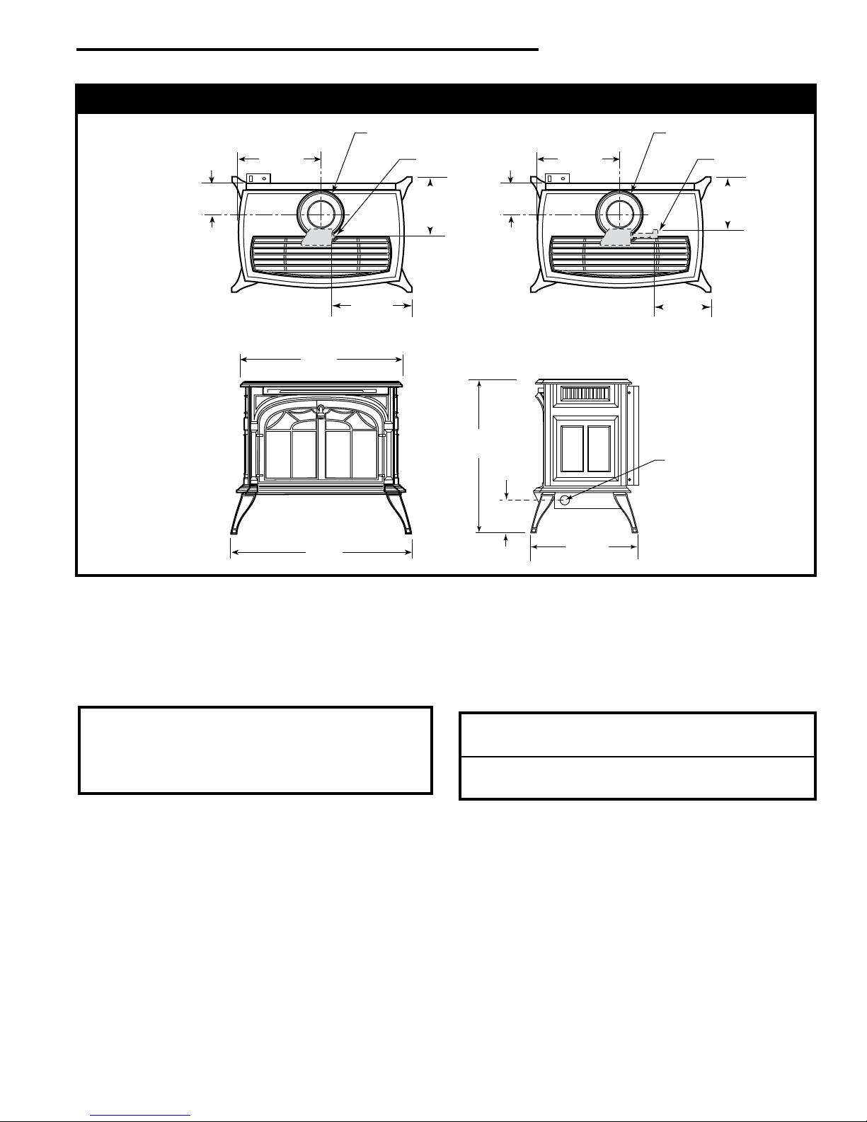
29³⁄₄"
(758 mm)
31"
(787 mm)
7" Outer Dia.
(178 mm)
Flue Collar
L
C
4³⁄₄"
(120 mm)
14⁷⁄₈"
(378 mm)
RADIANCE
28"
(711 mm)
5"
(127 mm)
18¹⁄₄"
(464 mm)
Supply
Inlet
9¹⁄₂"
(241 mm)
RADVT Models
7" Outer Dia.
(178 mm)
Flue Collar
L
C
4³⁄₄"
(120 mm)
14⁷⁄₈"
(378 mm)
8⁹⁄₁₆"
(218 mm)
RADVTC Models
Supply Inlet Supply Inlet
11”
(279 mm)
13³⁄₈”
(340 mm)
Radiance Direct Vent Stove Dimensions
See Page 7 for Flue Collar
Centerline Dimensions.
Radiance® Direct Vent Gas Heater
Fig. 1 Radiance dimensions.
Proposition 65 Warning: Fuels used in gas, woodburning or
oil red appliances, and the products of combustion of such
fuels, contain chemicals known to the State of California to
cause cancer, birth defects and other reproductive harm.
California Health & Safety Code Sec. 25249.6
ANSI Z21.88-2009 / CSA 2.33-2009
Radiance Direct Vent
Certied to:
Vented Gas Fireplace Heaters
20306759
5
Radiance® Direct Vent Gas Heater
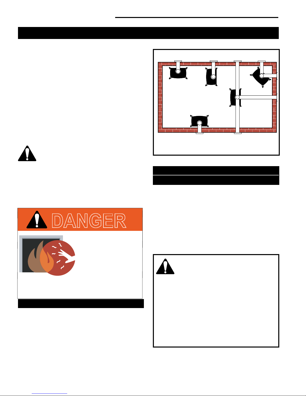
A
B
E
C
D
Installation Requirements
The installation must conform with local codes or, in the
absence of local codes, with the National Fuel Gas Code,
ANSI Z223.1/NFPA 54 - latest edition. (EXCEPTION: Do
not derate this appliance for altitude. Maintain the manifold pressure at 3.5" w.c. for Natural Gas, and 10" w.c. for
Propane).
In Canada, installation must be in accordance with the current CSA B-149.1 Installation Codes and/or local codes.
The installation should be done by a qualied service
person who is familiar with the building codes and
installation techniques appropriate for your area to
accomplish a safe and effective installation.
Your dealer or your local gas supplier will be able to
refer a qualied service person.
WARNING: Due to high temperatures, the HEATER
should be located out of trafc and away from
furniture and draperies.
The surface of the Heater Is hot when it is in
use. Young children should be watched carefully when
they are in the same room when the Heater is in use,
and they should be taught to avoid the hot surface.
Keep any objects that can burn well away from the
Heater, and observe the recommended clearances
that follow.
DANGER
HOT GLASS WILL
CAUSE BURNS.
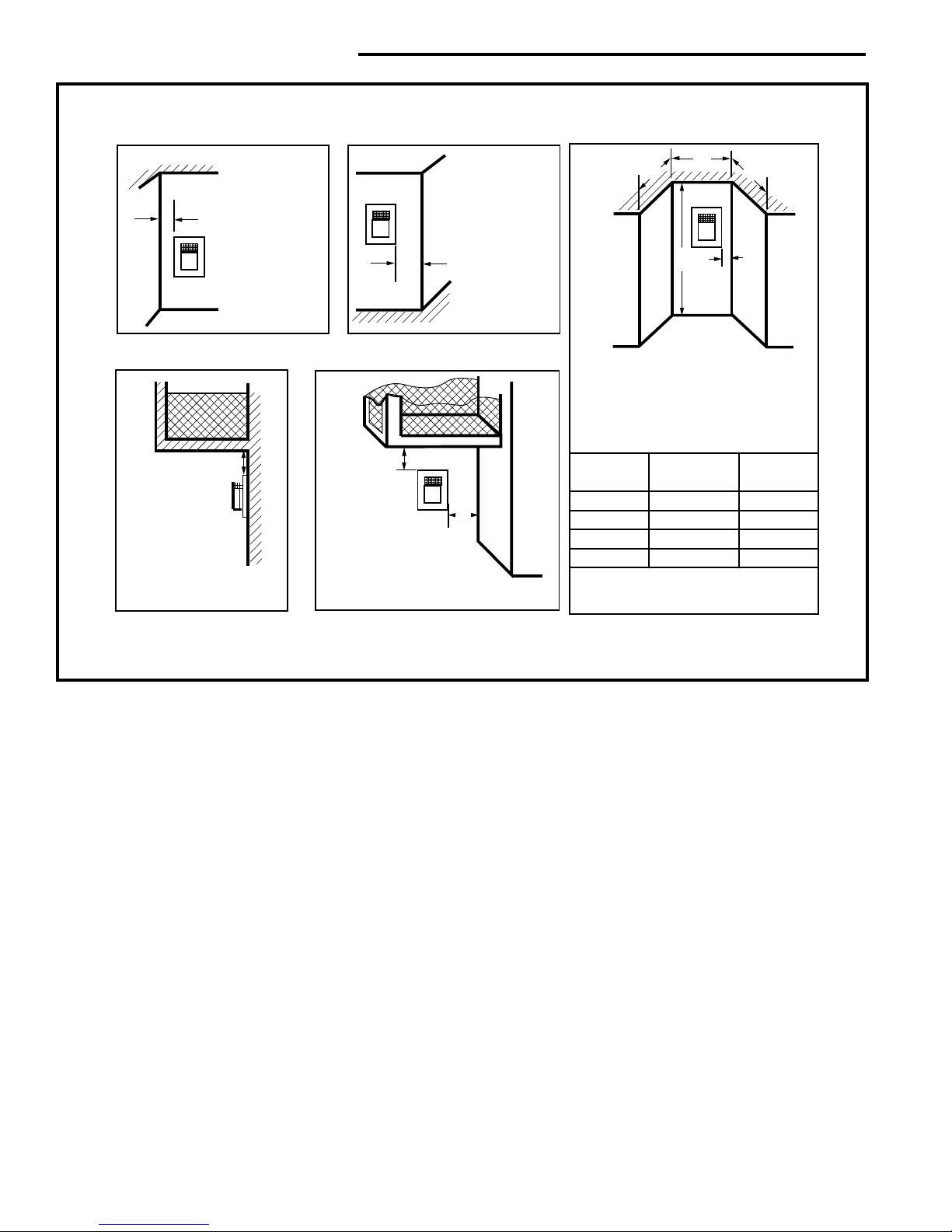
Direct Vent System Only
A. Flat on corner wall
B. Room Divider
C. Island
Fig. 2 Possible stove locations.
D. Cross Corner
E. Flat on wall
ST207a
Clearance Requirements
Minimum Clearances to Combustible Materials
Measure side clearances as shown in Figures 3, 4 and 5
from the outer edge of the cast iron stove top. Measure
rear clearances from the outermost surface of the steel
rear skirt.
The Radiance heater is approved for installation into an
alcove constructed of combustible materials to the dimensions and clearances shown on the next page.
The same clearances apply in a standard parallel installation.
DO NOT TOUCH GLASS
UNTIL COOLED.
NEVER ALLOW CHILDREN
TO TOUCH GLASS.
A barrier designed to reduce the risk of burns from
the hot viewing glass is provided with this
appliance and shall be installed.
Locating The Stove
In choosing a location for the stove, consider:
• The location of outside walls;
• Where additional heat is needed:
• Where family members gather most often;
• The vent system requirements.
NOTE: We do not recommend the use of wallpaper next
to this stove. Over time, radiant heat may cause the wallpaper to shrink, or may adversely affect the binders in the
wallpaper adhesive.
66
WARNING:
• Always maintain required clearances (air
spaces) to nearby combustibles to prevent
re hazard. Do not ll air spaces with insu-
lation. All venting components must maintain a
1" (25 mm) clearance to combustible materials.
Maintain a 6" (150 mm) clearance when using
single wall pipe.
• The gas appliance and vent system must be vented
directly to the outside of the building and never
be attached to a chimney serving a separate solid
fuel or gas-burning appliance.
• Refer to the manufacturer’s instructions included
with the venting system for complete installation
procedures.
20306759
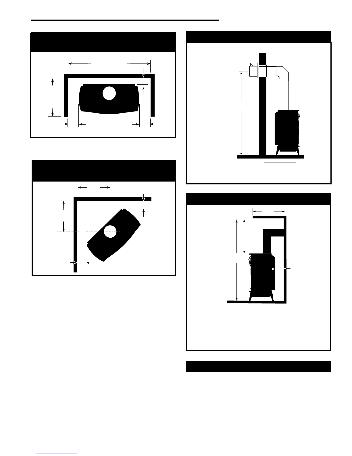
Radiance® Direct Vent Gas Heater
42" (1070mm)
Min. Alcove Width
48"
(1220mm)
Max. Alcove
Depth
6"
(150mm)
6"
(150mm)
4" (102mm)
18"
(457mm)
18"
(457mm)
6"
(150mm)
6"
(150mm)
C
L
C
L
A
A
C
D
B
Parallel Installation:
Minimum Clearance and Flue Centerline
ST130
Fig. 3 Parallel installation, minimum back and side clear-
ances, and ue centerlines.
Corner Installation:
Minimum Clearance and Flue Centerline
Wall Centerline from Floor
Direct Vent Only
A
Effective Minimum
Centerline 57" (1448 mm)
(Vermont Castings Group Pipe)
55" (1399 mm) (DuraVent Pipe)
Fig. 5 Minimum wall centerline.
Wall and Ceiling Clearances
ST131b
Fig. 4 Corner installation, minimum corner clearances and
ue centerline.
20306759
ST129
Direct Vent Only
A: Rear Wall 4" (102 mm)
B: Min. Clearance 44" (1118 mm)*
C: Min. Alcove Height 72" (1830 mm)*
D: Max. Alcove Depth 48" (1220 mm)
Sidewall Clearance 6" (150 mm)
* needed for installing DuraVent Minimum Vent Kit #2792 or
Vermont Castings Group Minimum Vent Kit #7TFSMSK.
ST101b
Fig. 6 Dimensions and clearances to ceiling or alcove.
Hearth Requirements
The Radiance Heater must be installed on rigid ooring.
When the heater is installed directly on any combustible
surface other than wood ooring, a metal or wood panel
extending the full width and depth of the unit must be used
as the hearth. There are no other hearth requirements.
7
Radiance® Direct Vent Gas Heater
20
19
18
16
15
14
13
12
11
10
9
8
7
6
5
4
3
2
1
0
1 2 3 4 5 6 7 8 9 10 11 12 13 14 15 16 17 18 19 20
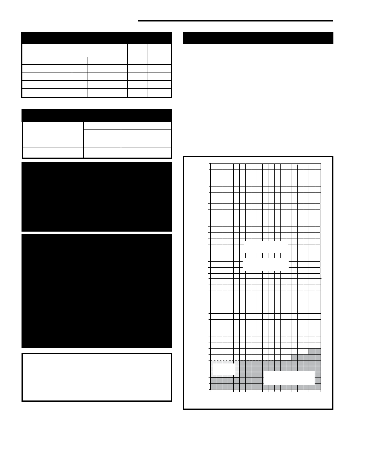
Vertical Run (in feet)
(Measured from the appliance flue collar to the top of the vent pipe.)
Horizontal Run (in feet)
21
22
23
24
25
26
27
28
29
30
31
32
33
34
35
36
37
38
39
40
ST134b
Radiance
Horizontal
vent run
6/07
Gas Specications
Max. Min.
Input Input
Model Fuel Gas Control BTU/h BTU/h
RADVT Series Nat Millivolt Manual 38,000 25,000
RADVT Series Prop Millivolt Manual 36,000 25,000
RADVTCS Series Nat Millivolt Hi/Lo 38,000 25,000
RADVTCS Series Prop Millivolt Hi/Lo 36,000 25,000
Weight: Fully assembled; 350 lbs.
Gas Inlet and Manifold Pressures
Natural LP (Propane)
Inlet Minimum 5.5" w.c. 11.0" w.c.
Inlet Maximum 14.0" w.c. 14.0" w.c.
Manifold Pressure 3.5" w.c. 10" w.c.
The installation of your Vermont Castings stove must
conform with local codes, or in the absence of local
codes, with the National Fuel Gas Code ANSI Z223.1/
NFPA 54 - latest edition, or CSA B149.1 Installation code.
(EXCEPTION: Do not derate this appliance for altitude up
to 2,000 (610 m) for natural gas and 4,500 feet (1,370
m) for LP Gas. Maintain the manifold pressure at 3.5"
w.c. for Natural Gas and 10.0" w.c. for LP Gas.
Horizontal Termination
The vent must rise vertically a minimum of 24" (610 mm)
off the top of the unit, before the rst elbow. The horizontal
run may extend up to 20’ (6m) and include a vertical rise of
up to 40’ (12 m). (Fig. 7) Horizontal termination must also
meet the criteria shown in Figures 10 through 12.
• Approved vent systems must terminate above and including the heavy line in Figure 7.
• Two 45° elbows may be substituted for each single 90°
elbow.
• With a rise between 2’ - 5’, one 90° or two 45° elbows
may be used.
Input ratings are shown in BTU per hour and are
certied without deration for elevations up to 2,000
feet (610 m) for natural gas and 4,500 feet (1,370 m)
for LP gas above sea level.
In the USA installations with elevations above 2,000
feet (610 m) for natural gas and 4,500 feet (1,370 m)
for LP gas must be in accordance with the current
ANSI Z223.1/NFPA 54 and/or local codes having
jurisdiction.
In Canada, please consult provincial and/or local
authorities having jurisdiction for installations at
elevations above 2,000 feet (610 m) for natual gas
and 4,500 feet (1,370 m) for LP gas.
WARNING: Improper installation, adjustment, alteration, service or maintenance can cause injury
or property damage. Refer to this manual for correct
installation and operational procedures. For assistance or additional information consult a qualied
installer, service agency, or the gas supplier.
88
High Elevations
May use up to
three 90° Elbows
No Restrictor Plate
Required
One 90°
Elbow
Unacceptable
Venting Conguration
Fig. 7 Horizontal vent termination window.
ST134a
20306759
Radiance® Direct Vent Gas Heater
20
19
18
16
15
14
13
12
11
10
9
8
7
6
5
4
3
2
1
0
20
1 2 3 4 5 6 7 8 9 10 11 12 13 14 15 16 17 18 19
Vertical Run (in feet)
(Measure from the appliance flue collar to the top of the vent pipe.)
Horizontal Run (in feet)
21
22
23
24
25
26
27
28
29
30
31
32
33
34
35
36
37
38
39
40
ST132a
FDV28
Vertical
vent run
12/3/99 djt
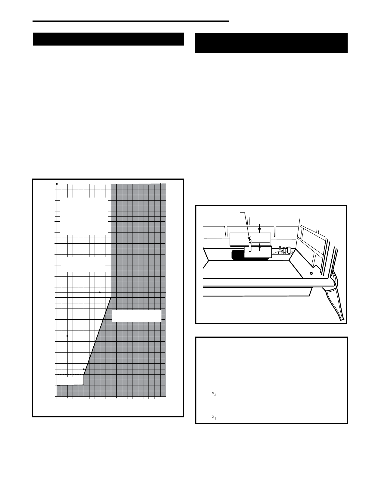
Vertical Termination
A vertical vent system must terminate no less than 8’ (2.44
m) and no more than 40’ (12 m) above the appliance ue
collar. A restrictor plate (supplied) must be used, where
specied, in all vertically terminated vent systems. (Refer
to Figure 8) NOTE: The restrictor plate supplied with
the vertical termination should be discarded. Adjust
the restrictor plate according to recommendations in
Figure 10. A vertically terminated vent system must also
conform to the following criteria:
• No more than three 90° elbows may be used.
• Two 45° elbows may be substituted for one 90° elbow.
No more than six 45° elbows may be used.
• Vent must rise a minimum of 2 feet (305 mm) before
offset is used.
• Termination height must conform to roof clearance as
specied in Figure 11.
All Vertical Ter-
minations in this
area Require use
of the Restrictor
Plate*
Restrictor Plate Adjustment
for Extended Pipe Runs
The Radiance stove is shipped with a restrictor plate in
the Parts Bag. Adjustments can be made by loosening the
adjustment screw to allow the restrictor plate to slide up or
down. (Fig. 9) A guide for usage is shown in Figure 10.
NOTE: Some installations may require some adjustment
by the installer for optimum ame appearance. Optimum
ame appearance is a ame that is not subject to tall, dirty
yellow ames producing soot or ames lifting off of the
ember bed ports.
Restrictor Plate Adjustment
1. Remove the screw in the back wall of the rebox.
2. Install restrictor plate as shown in Figure 9 with cut out
on left side. Secure with adjustment screw.
2. Measure from center of screw to top edge of diverter
(Fig. 9) to adjust plate according to guidelines in Figure 10.
3. Tighten attachment screw.
4. Install logs following log installation instructions.
Adjustment Screw
**No Restrictor
Plate
Fig. 8 Vertical vent termination window.
20306759
Vertical terminations
must be within this
area
Unacceptable
Venting Conguration
**
ST132a
ST917
Fig. 9 Loosen screw to adjust restrictor plate.
Examples for Extended Run/Restrictor Plate Settings
1. Vertical 20’ (6 m), 90° elbow, out 8’ (2.4 m)
2. Vertical 11’ (3.4 m), 90° elbow, out 2’ (610 mm)
3. Vertical 40’ (12 m)
4. Vertical 5’ (1.5 m), 90° elbow, out 5’ (1.5 m)
Restrictor plate measurement from top of plate to center of
screw:
3
⁄4" (70 mm) from center of screw to top edge of plate
1. 2
2. Plate down to top of slot
3. Plate down to top of slot
4. 23⁄8" (60 mm) from center of screw to top edge of plate
Figure 10
9
Radiance® Direct Vent Gas Heater
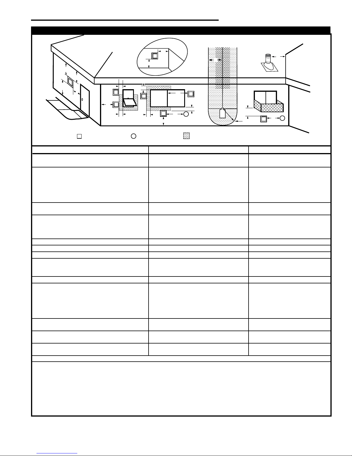
Vent Termination Clearances
When planning the installation, consider the location of the
vent terminal and clearances. Some of the most common
clearances to keep in mind are shown in Figure 11.
Important: All vent clearances must be maintained.
Check your vent termination clearances against Fig-
ures 11 through 13.
The vent should be placed so that people cannot be burned
by accidentally touching the vent surfaces when the stove
is operating.
The vent termination should be located where it cannot be
damaged by such things as automobile doors, lawn mowers
or snowblowers and it should be located away from areas
where it could become blocked by snow, etc.
Some considerations are:
• Obstructions or impediments to venting.
• Nearby combustible materials that could come into
contact with combustion exhaust gases.
• Other nearby openings {within 12" (305 mm)} through
which exhaust gas could reenter the building.
• All vegetation within 3’ (76 mm) that may interfere with
the draft.
Other factors that inuence where the installation will be
sited include the location of outside walls, where additional
heat may be desired in the home, where the family members gather most regularly, and perhaps most importantly,
the distance limitations of the venting system.
Your stove is approved to be vented either through the side
wall, or vertical through the roof.
• Vermont Castings Group does not require any open-
ing for inspection of vent pipe.
• Only Vermont Castings Group, DuraVent and Selkirk
Corporation venting components specically approved and
labelled for this stove may be used.
• Minimum clearances between vent pipes and combus-
tible materials is one (1") inch (25 mm), except where stated
otherwise.
• Venting terminals shall not be recessed into a wall or siding.
• Horizontal venting must be installed on a level plane without
an inclining or declining slope.
There must not be any obstruction such as bushes, garden
sheds, fences, decks or utility buildings within 24" from the
front of the termination hood.
Do not locate termination hood where excessive snow or ice
build up may occur. Be sure to check vent termination area
after snow falls, and clear to prevent accidental blockage
of venting system. When using snow blowers, make sure
snow is not directed towards vent termination area.
Location of Vent Termination
It is imperative the vent termination be located observing
the minimum clearances as shown on this page.
IMPORTANT
• The horizontal termination must not be recessed
into the exterior wall or siding.
• Horizontal vent runs must be level toward the vent
termination.
• Clearances around the vent termination must be
maintained.
• For installations using DuraVent pipe, parallel
installations with minimum wall clearance have
restricted access for connecting the Horizontal
Vent Cap straps to the vent pipe. See the maker’s
instructions for recommended installation procedures.
1010
20306759
Radiance® Direct Vent Gas Heater
V
X
X
X
D
E
B
B
B
C
B
M
B
A
J
K
F
L
VENT TERMINATION AIR SUPPLY INLET
AREA WHERE TERMINAL IS NOT PERMITTED
H
I
Fixed
Closed
Operable
Operable
Fixed
Closed
B
INSIDE
CORNER DETAIL
A
G
CFM145a
V
V
V
V
V
V
V
V
N
General Venting Information - Termination Location
Canadian Installations1 US Installations
A = Clearance above grade, veranda, porch, 12" (30 cm) 12" (30 cm)
deck, or balcony
B = Clearance to window or door that may be 6" (15 cm) for appliances 6" (15 cm) for appliances
opened < 10,000Btuh (3kW), 12" (30 cm) < 10,000 Btuh (3kW), 9"
for appliances > 10,000 Btuh (3kW) and (23 cm) for appliances > 10,000
< 100,000 Btuh (30kW), 36" (91 cm) Btuh (3kW) and < 50,000 Btuh
for appliances > 100,000 Btuh (30kW) (15kW), 12" (30 cm) for
appliances > 50,000 Btuh (15kW)
C = Clearance to permanently closed window 12" (305 mm) recommended to 12" (305 mm) recommended to
prevent window condensation prevent window condensation
D = Vertical clearance to ventilated soft located
above the terminal within a horizontal 18" (458 mm) 18" (458 mm)
distance of 2’ (610mm) from the center
line of the terminal
E = Clearance to unventilated soft 12" (305 mm) 12" (305 mm)
F = Clearance to outside corner see next page see next page
G = Clearance to inside corner (see next page) see next page see next page
H = Clearance to each inside of center line 3’ (91 cm) within a height of 15’ (5 m) 3’ (91 cm) within a height of 15’
extended above meter/regulator assembly above the meter/regulator assembly (5 m) above the meter/regulator
assy
I = Clearance to service regulator vent outlet 3’ (91 cm) 3’ (91 cm)
J = Clearance to nonmechanical air supply inlet 6" (15 cm) for appliances < 10,000 6" (15 cm) for appliances
to building or the combustion air inlet to any Btuh (3kW), 12" (30 cm) for < 10,000 Btuh (3kW), 9"
other appliances appliances > 10,000 Btuh (3kW) and < (23 cm) for appliances > 10,000
100,000 Btuh (30kW), 36" (91 cm) Btuh (3kW) and < 50,000 Btuh
for appliances > 100,000 Btuh (30kW) (15kW), 12" (30 cm) for
appliances > 50,000 Btuh (15kW)
K = Clearance to a mechanical air supply inlet 6’ (1.83 m) 3’ (91 cm) above if within 10’
(3 m) horizontally
L = Clearance above paved sidewalk or paved 7’ (2.13 m)† 7’ (2.13 m)†
driveway located on public property
M = Clearance under veranda, porch, deck or 12" (30 cm)** 12" (30 cm)**
balcony
N = Clearance to any other obstruction within a horizontal distance of 18" (450 mm).
1 In accordance with the current CSA-B149 Installation Codes
2 In accordance with the current ANSI Z223.1/NFPA 54 National Fuel Gas Codes
† A vent shall not terminate directly above a sidewalk or paved driveway which is located between two single family dwellings and serves both dwellings
** only permitted if veranda, porch, deck or balcony is fully open on a minimum 2 sides beneath the oor:
NOTE: 1. Local codes or regulations may require different clearances.
2. The special venting system used on Direct Vent Stoves are certied as part of the appliance, with clearances tested and approved by the list-
ing agency.
3. Vermont Castings Group assumes no responsibility for the improper performance of the appliance when the venting system does
not meet these requirements.
Fig. 11 Vent termination clearances.
20306759
2
11
Radiance® Direct Vent Gas Heater
Termination Clearances
Termination clearances for buildings with combustible and noncombustible exteriors.
Inside Corner
G =
G
Combustible
6" (152 mm)
Noncombustible
V
2" (51 mm)
Outside Corner
V
F
F =
Combustible
6" (152 mm)
Noncombustible
2" (51 mm)
Alcove Applications*
D
C
V
O
C
E
Balcony -
with no side wall
M
V
M =
Combustible &
Noncombustible
12" (305 mm)
*NOTE: Termination in an alcove space (spaces open only on one side and with an overhang) is permitted with the dimensions
specied for vinyl or non-vinyl siding and softs. 1. There must be a 3’ (914 mm) minimum between termination caps. 2. All mechanical air intakes within 10’ (1 m) of a termination cap must be a minimum of 3’ (914 mm) below the termination cap. 3. All gravity
air intakes within 3’ (914 mm) of a termination cap must be a minimum of 1’ (305 mm) below the termination cap.
Fig. 12 Termination clearances.
Balcony -
with perpendicular side wall
M
V
P
Combustible &
Noncombustible
M = 12" (305 mm)
P = 6” (152 mm)
E = Min. 2” (51 mm) for
non-vinyl sidewalls
Min. 12” (305 mm) for
vinyl sidewalls
O = 8’ (2.4 m) Min.
No.
of Caps D
1 3’ (914 mm) 2 x D
2 6’ (1.8 m) 1 x D
3 9’ (2.7 m) 2/3 x D
4 12’ (3.7 m) 1/2 x D
D
= # of Termination caps x 3
Min.
C
= (2 / # termination caps) x D
Max.
C
Min.
Max.
Actual
Actual
Actual
Actual
Actual
584-15
1212
20306759

Radiance® Direct Vent Gas Heater
Venting Requirements and Options
Approved Vent System Components
The Radiance Heater must be vented to the outdoors
through an adjacent exterior wall or through the roof. The
venting system must be comprised of the appropriate listed
venting components specied on this page. These parts are
available from DuraVent Corporation, Selkirk Corporation
or your Vermont Castings Dealer.
See Figure 4 for dimensions relevant to the standard minimum-vent kits.
DuraVent Components
www.duravent.com
Phone: 1-800-835-4429, Fax: 1-707-446-4740
Minimum Horizontal Vent Kit 2792
Starter Pipe Assembly (incl. inner & outer sections) 2768*
90° Elbow, Blk. 46DVA-E90B*
45° Elbow, Gal. 46DVA-E45
6" Straight, Blk. 46DVA-06B*
9" Straight, Blk. 46DVA-09B
11" - 145⁄8" Adjustable Straight Section 46DVA-08AB
12" Straight 46DVA-12
24" Straight 46DVA-24B*
36" Straight 46DVA-36B
48" Straight 46DVA-48
Horizontal Vent Cap 46DVA-HC*
Wall Plate 46DVA-DC
Vinyl Siding Shield 46DVA-VSS
Snorkel Termination - 14" 46DVA-SNK14
Snorkel Termination - 36" 46DVA-SNK30
Wall Strap 46DVA-WS
Cathedral Ceiling Support Box 46DVA-CS
Storm Collar 46DVA-SC
Firestop Spacer 46DVA-FS
Flashing 0/12 - 6/12 46DVA-F6
Flashing 6/12 - 12/12 46DVA-F12
Steel Chimney Conversion Kit
Kit A (65⁄8" - 85⁄8") 46DVA-KCA
Kit B (65⁄8" - 101⁄2") 46DVA-KCB
Kit C (65⁄8" - 13") 46DVA-KCC
Masonry Chimney Conversion Kit 46DVA-KMC
Vertical Termination Cap (High Wind) 46DVA-VCH
Vertical Termination Cap (Low Prole) 46DVA-VC
*Included in Minimum Horizontal Vent Kit #2792
All DuraVent Straight vent pipe sections have a net length 11⁄2"
(37mm) less than the nominal dimension; i.e., a 6" (152 mm)
Straight pipe section has an effective length of 41⁄2" (115 mm).
Selkirk Corporation Vent Components
www.selkirkcorp.com
1301 W. President George Bush Highway Ste. 330
Richardson, TX 75080
Phone: 1-800-992-8368, Fax: 1-877-393-4145
Appliance Adapter 4DT-AAV
90° Elbow, Blk. 4DT-EL90B
45° Elbow, Blk. 4DT-EL45B
6" Straight, Blk. 4DT-06B
9" Straight, Blk. 4DT-09B
4" - 10" Adjustable Straight Section, Blk. 4DT-AJ12
12" Straight, Blk. 4DT-12B
18" Straight, Blk. 4DT-18B
24" Straight, Blk. 4DT-24B
36" Straight, Blk. 4DT-36B
48" Straight, Blk. 4DT-48B
Horizontal Vent Cap 4DT-HC
Wall Plate 4DT-WT
Vinyl Siding Shield 4DT-VS
Snorkel Termination - 14" 4DT-ST14
Snorkel Termination - 36" 4DT-ST36
Wall Strap 4DT-WS/B
Cathedral Ceiling Support Box 4DT-CCS
Storm Collar 4DT-SC
Firestop Spacer 4DT-FS
Flashing 0/12 - 6/12 4DT-AF6
Flashing 6/12 - 12/12 4DT-AF12
Steel Chimney
Horizontal Kit A 4DT-HKA
Horizontal Kit B 4DT-HKB
Vertical Kit 4DT-VKC
Masonry Chimney Kit 4DT-MCK
Vertical Termination Cap 4DT-VC
20306759
13

Radiance® Direct Vent Gas Heater
Vermont Castings Group Vent Components
The following kits are available to meet the needs of most
installations. All pipe has a 7" outer diameter and includes
a 4" diameter inner section. A (CG) designation indicates
the part is nished in Charcoal Gray paint. Consult your
dealer about other vent parts that may be appropriate to
complete the installation.
Min. Through the Wall Vent Kit 7TFSSK
(1) 90-Degree Elbow (CG) (7537517)
(1) 24" Straight pipe (CG) (20001448)
(1) 24" - 42" Adjustable Straight Pipe (20006759)
(1) Side Wall Termination (06508)
(1) Firestop (50534)
(1) Zero-clearance sleeve (54623)
(1) Hardware package (20000160)
(1) Finishing plate (CG) (10000257)
(1) Finishing collar (CG) (56298)
(4) Charcoal Gray ue pipe rings (10001008)
Starter Kit for Below-Grade Termination 7TDVSKS
(1) Snorkel Termination (7TDVSNORK)
Vertical Termination Kit, 1/12-6/12 Pitch 7TDVSKVA
(1) Combination Horizontal Offset / Roof Support
(1) Vertical Termination
(1) Storm Collar
(1) 1/12-6/12 Flashing
(1) Finishing Plate (CG)
(1) Finishing Collar (CG)
(1) Polished Brass Flue Pipe Ring
(1) Hardware Package
Vertical Termination Kit, 7/12-12/12 Pitch 7TDVSKVB
(1) 7/12 - 12/12 Flashing
and all of the other Vertical Termination parts.
Vertical Termination, Flat Roof 7DVSKVF
(1) Flat Flashing
and all of the other Vertical Termination parts.
Twist Lock 12" Straight Pipe (CG) 7TFSDVP12
(1) 12" Non-adjustable Pipe
Twist Lock 12" - 18" Adjustable Pipe 7TFSDVP1218
(1) 12" - 18" Adjustable Pipe
Twist Lock 24" Straight Pipe (CG) 7TFSDVP24
(1) 24" Non-adjustable Pipe
Twist Lock 48" Straight Pipe (CG) 7TFSDVP48
(1) 48" Nonadjustable Pipe
Twist Lock 45-Degree Elbow (CG) 7TFSDVT45
for vertical offsets
(1) 45-degree Elbow
Combination Offset/Roof Support 7DVCS
Attic Insulation Shield 7DVAIS
7" Charcoal Gray Pipe Rings, (4) 7FSDRG
7" Polished Brass Pipe Rings (4) 7FSDRP
Wall Thimble 942G
1414
20306759
Radiance® Direct Vent Gas Heater
Assembly Procedures
Failure to position the parts in accor-
dance with these diagrams or failure to
use only parts specically approved for
use with this heater may result in property damage
or personal injury.
This heater and components are heavy. Have help
available for assembly.
WARNING
Tools Required
• Phillips screwdriver (stub) • power drill
• utility knife • reciprocating saw
• metal drill bit: size 28 (.140"/3.5mm) • 9/16" wrench
• Flat-blade screwdriver
Parts Bag Contents:
•
(3) Vent Screws
• (2) Switch bracket screws
• Wood handle w/insert lifter
(handle for operable door)
• Restrictor Plate
• 4" Starter pipe
• On-Off switch, housing, and wiring harness
(3) Phillips round-head bolts, 1/4"- 20 x 1/2"
• (1) Tube of Vent Gasket Cement
• (4) CS, Hex Hd 3/8-16 x 1 Gr 2-Z
• (4) Washer, Fl 3/8-Z
• Owner Registration Card
• Homeowner’s Installation and Operating Manual
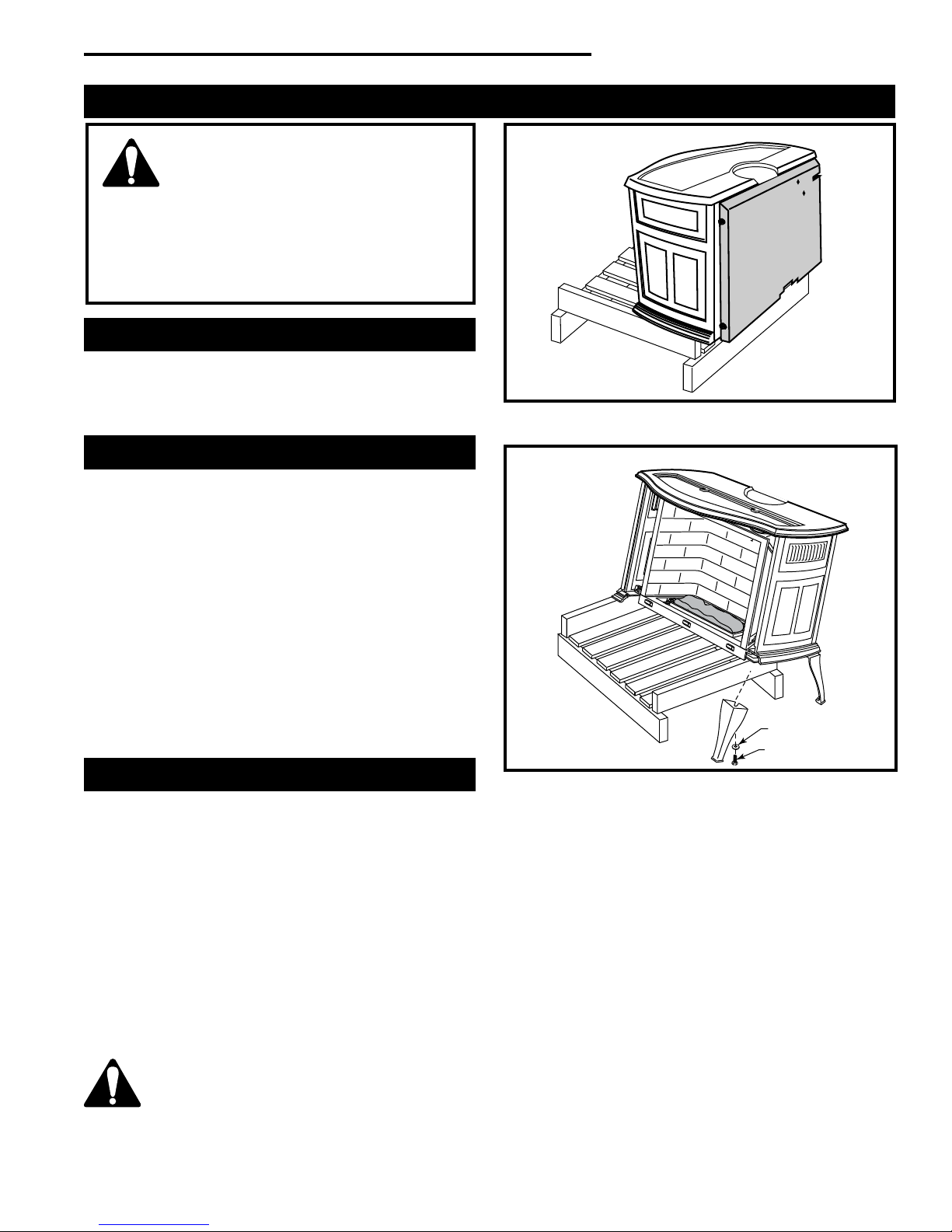
Unpack and Assemble Legs
The Radiance is shipped upright. Cut the shipping straps
before beginning assembly.
1. Slide stove to the rear of the pallet just far enough to
access rear leg holes. Make sure the stove does not
tip over backwards. (Fig. 13)
2. Attach the rear legs using 3/8" hex head bolts and at
washer supplied. Tighten with a 9/16" wrench or socket.
Remove and discard the large slot-head screws using
the at-blade screwdriver.
3. Carefully tip the stove onto its rear legs. Adjust the pallet
to allow access to one of the front leg holes. Be sure
to leave the pallet under the stove to prevent the stove
from falling fully forward. (Fig. 14)
CAUTION: To prevent valve tubing from being
crushed or damaged, do not rest valve or ignitor
on wooden pallet.
ST720
Fig. 13 Slide stove back just far enough to access rear leg
holes.
Washer
ST721
Fig. 14 Carefully tip stove onto back legs. Leave pallet under
stove to keep stove from falling fully forward.
4. Have your assistant attach one leg using the hardware
described.
5. Move the pallet to allow access to the other front leg
hole. Attach remaining leg.
6. Remove pallet and allow stove to gently rest on all four
legs.
7. Adjust leg levelers to compensate for irregularities in
the hearth.
NOTE: Verify the two relief doors (located on top of the
rebox) are properly seated on the gasket. The doors
should sit ush on the gasket, and should lift easily
from the seal around the opening.
Hex Head Bolt
20306759
15
Radiance® Direct Vent Gas Heater
WARNING
This appliance is equipped with a three-prong
(grounded) plug for your protection against shock
hazard and should be plugged directly into a
properly grounded three-prong receptacle. Do not
cut or remove the grounding prong from this plug.
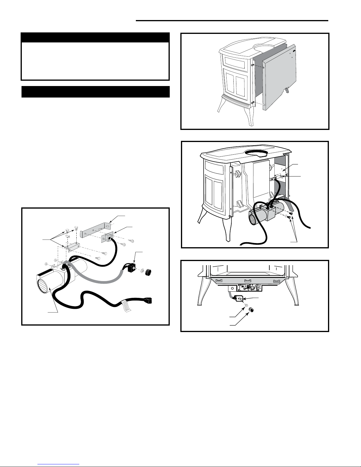
Install the Optional Fan - RADVT Series
If you are installing the optional convection Fan Kit #2767
(FK26), continue here. It is easiest to install fan kit before
connecting gas line. If you are not installing a Fan Kit, go
to Page 17, Venting System Assembly.
1. The fan kit includes a Blower Assembly and a Rheostat
Assembly, connected by a cable. (Fig. 15) The Blower
Assembly mounts to the bottom rear of the stove, and
the Rheostat mounts to the valve coverplate. The assembly includes a ‘snapstat’ which automatically turns
the fan On (or Off) above (or below) approximately 109°.
The Rheostat also provides a range of fan speed settings from Off (which overrides the snapstat function) to
High. Unpack and inspect the Blower assembly. Conrm
that the fan spins freely.
ST147
Fig. 16 Remove rear shroud.
Side Shield
Snapstat
Snapstat
Bracket
Not
Used On
Radiance
Blower
Assembly
ST473a
Fig. 15 Fan kit components.
Snapstat/
Extension
Assembly
Rheostat
Assembly
2. Remove the rear shroud panel (Fig. 17) and fasten the
blower assembly to the rebox back with the two bolts
provided. (Fig. 17)
3. Attach the snapstat assembly to the snapstat bracket
with two sheet-metal screws. Attach the snapstat bracket
to the side shield. (Fig. 17)
4. The rheostat control switch attaches to the left side of
the valve bracket at the front of the stove. (Fig. 18)
• Remove retaining nut from shaft of rheostat. (if pre-
installed)
Bolts
Fig. 17 Attach blower assembly and snapstat.
Rheostat
Rheostat
Retaining Collar
Rheostat Knob
Fig. 18 Attach the fan rheostat.
• Insert the rheostat through the hole in the back of
the left side of the valve bracket, aligning the locator
pin with the smaller hole in that bracket.
• Thread the retaining nut onto the shaft of the rheo-
stat, tightening with a wrench. Do not overtighten.
• Attach the control knob to the rheostat shaft.
• Use the wire tie to secure the fan and rheostat wire
harnesses together.
ST149
ST347a
1616
20306759
 Loading...