

Vermont Castings Radiance RADVTSCBM, Radiance RADVTSCBD, Radiance RADVTCBSB, Radiance RADVTBSSB, Radiance RADVTBDSB Installation And Operating Instructions Manual
...Page 1
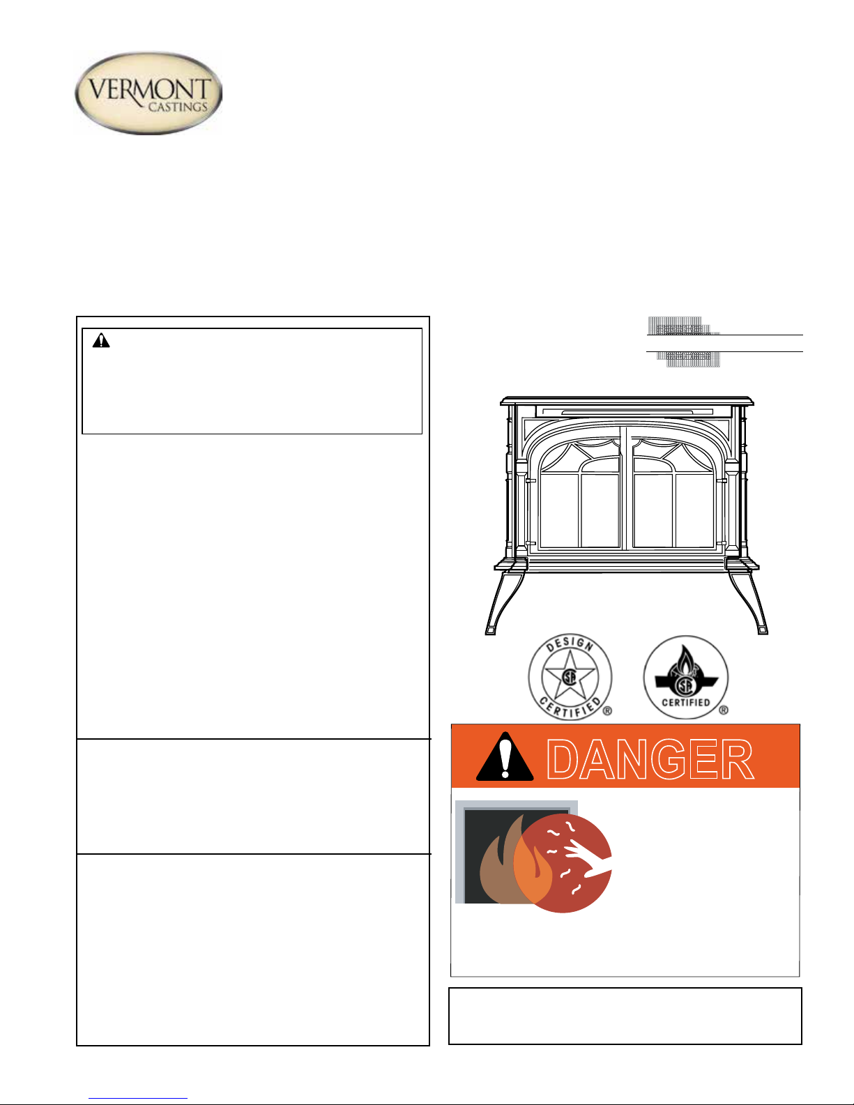
RADVT Series Radiance® Direct Vent Gas Heater
S
Installation and Operating Instructions
Models: RADVTSCCB, RADVTSCBS, RADVTSCBD, RADVTSCBM,
RADVTCBSB, RADVTBSSB, RADVTBDSB, RADVTBMSB
WARNING:
FIRE OR EXPLOSION HAZARD
Failure to follow safety warnings exactly
could result in serious injury, death or
property damage.
• Do not store or use gasoline or other
ammable vapors and liquids in the
vicinity of this or any other appliance.
• WHAT TO DO IF YOU SMELL GAS
– Do not try to light any appliance.
– Do not touch any electrical switch; do
not use any phone in your building.
– Leave the building immediately.
– Immediately call your gas supplier from
a neighbor's phone. Follow the gas
supplier's instructions.
– If you cannot reach your gas supplier,
call the re department.
• Installation and service must be performed
by a qualied installer, service agency or
the gas supplier.
WARNING: Improper installation, adjustment,
alteration, service or maintenance can cause
injury or property damage. Refer to this manual.
For assistance or additional information consult
a qualified installer, service agency or the
gas supplier.
This appliance may be installed in an aftermarket,*
permanently located, manufactured home (USA
only) or mobile home, where not prohibited by
local codes.
This appliance is for use only with the type of gas
indicated on the rating plate. This appliance is
not convertible for use with other gases, unless
a certied kit is used.
* Aftermarket: Completion of sale, not for purpose of resale, from
the manufacturer.
CERTIFIED
AFETY BARRIER
DANGER
HOT GLASS WILL
CAUSE BURNS.
DO NOT TOUCH GLASS
UNTIL COOLED.
NEVER ALLOW CHILDREN
TO TOUCH GLASS.
A barrier designed to reduce the risk of burns from
the hot viewing glass is provided with this
appliance and shall be installed.
INSTALLER: Leave this manual with the appliance.
CONSUMER: Retain this manual for
future reference.
20306759 0416 Rev. 5
Page 2

CONTENTS
Radiance® Direct Vent Gas Heater
PLEASE READ THE INSTALLATION & OPERATING INSTRUCTIONS BEFORE USING APPLIANCE.
Thank you and congratulations on your purchase of a Vermont Castings stove. IMPORTANT: Read all instructions and
warnings carefully before starting installation. Failure to follow these instructions may result in a possible re hazard
and will void the warranty.
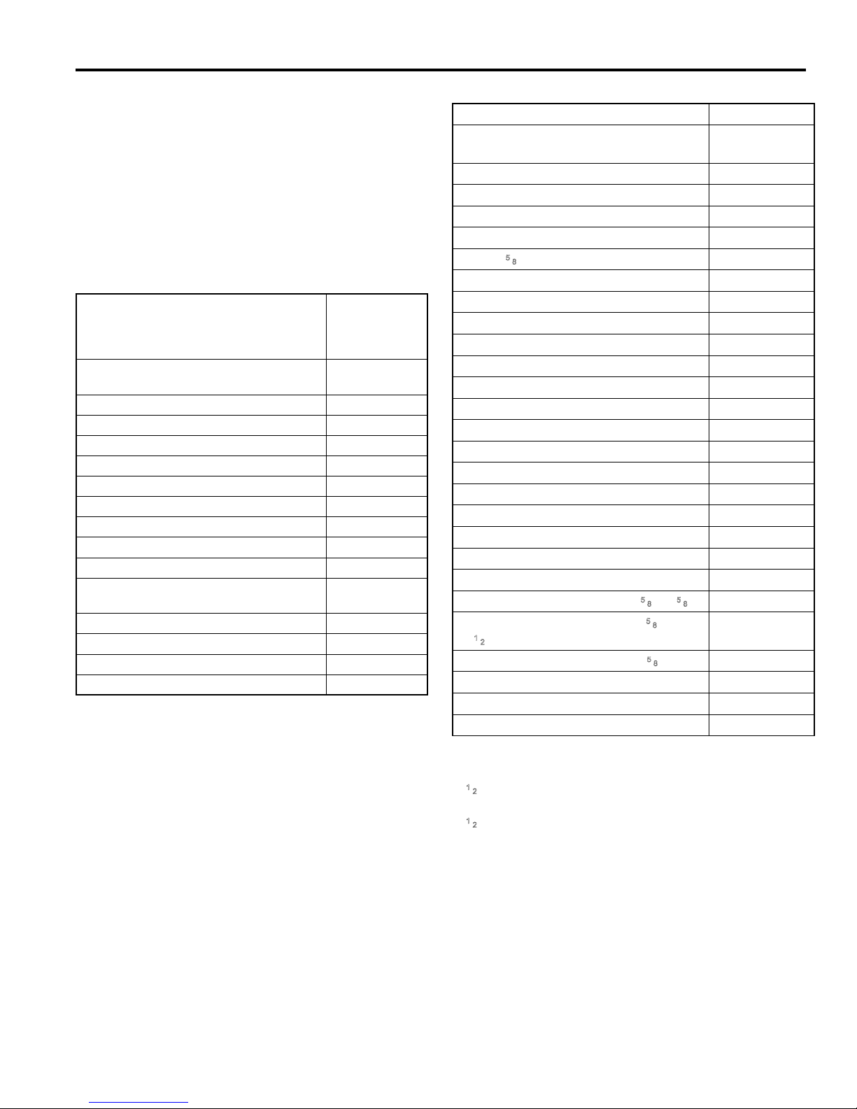
Table of Contents
Important safety information ....................................... 3
Massachusetts Residents Only ......................................... 4
Pre-installation.............................................................. 5
Stove Dimensions ............................................................. 5
Installation Requirements .................................................. 6
Clearance Requirements................................................... 6
Parallel Installation ............................................................ 7
Corner Installation ............................................................. 7
Wall and Ceiling Clearances ............................................. 7
Hearth Requirements ....................................................... 7
Gas Specications............................................................. 8
Gas Inlet and Manifold Pressures ..................................... 8
High Elevations ................................................................. 8
Horizontal Termination ...................................................... 8
Vertical Termination ........................................................... 9
Restrictor Plate Adjustment
for Extended Pipe Runs .................................................... 9
Vent Termination Clearances .......................................... 10
General Venting Information - Termination Location ........11
Termination clearances. .................................................. 12
Assembly and installation ......................................... 13
Venting Requirements and Options................................. 13
Assembling the Stove ..................................................... 14
Install the Optional Fan - RADVT Model (Millivolt only) �� 15
Venting System Assembly ............................................... 16
Before You Start .............................................................. 16
Install the Vent Adapter Pipe ........................................... 17
Assemble Slip Sections ................................................... 18
Secure the Vent Sections ................................................ 18
Disassemble Vent Sections ............................................. 19
Horizontal Termination Cap ............................................. 19
Divert Roof Run-off .......................................................... 20
Vertical Side Wall Installation .......................................... 20
Vent Termination Below Grade ........................................ 21
Vertical Through-The-Roof Application/Installation ......... 22
Install Log Set.................................................................. 24
Install ON/OFF Switch - RADVT Model (Millivolt only) .... 26
Thermostat Connection (optional) ................................... 26
Signature Command® System (SC) ............................... 26
Junction Box Wiring......................................................... 27
Command Center Wall Installation .................................. 27
Wall Switch Installation ................................................... 27
Connect the Gas Supply Line.......................................... 28
Burner Information........................................................... 28
Signature Command Wiring Diagram.............................. 29
Install the Safety Barrier .................................................. 30
Install the Mesh and Grill ................................................. 30
Operating instructions ............................................... 31
Pilot and Burner Inspection ............................................. 31
Flame & Temperature Adjustment ................................... 31
Flame Characteristics...................................................... 31
Lighting and Operating Instructions................................. 32
Troubleshooting ............................................................... 33
Read before lighting ........................................................ 34
Signature command operating instructions ............ 36
Features .......................................................................... 36
Battery installation ........................................................... 36
System conguration/setup ............................................. 36
Operating instructions ............................................... 38
Turning on the stove ........................................................ 38
Command Center Operations ......................................... 38
Initialization and Setting up ............................................. 39
Safety Features ............................................................... 43
Troubleshooting ......................................................... 44
Fuel conversion .......................................................... 46
Cleaning and maintenance ........................................ 51
Annual System Inspection ............................................... 51
Logset and Burner / Cleaning and Inspection ................. 51
Care of Cast Iron ............................................................. 51
Cleaning the Glass .......................................................... 51
Gasket Replacement ....................................................... 52
Inspect the Vent System Annually ................................... 52
Check the Gas Flame Regularly ..................................... 52
Glass Replacement ......................................................... 52
Wiring diagrams ......................................................... 53
Replacement parts ..................................................... 55
Optional accessories ................................................. 58
Limited lifetime warranty .......................................... 59
22 20306759
Page 3

Radiance® Direct Vent Gas Heater
IMPORTANT SAFETY INFORMATION
The Radiance Direct Vent Room Heater, Model Nos. RADVTCBSB, RADVTBSSB, RADVTBDSB, RADVTBMSB, RADVTSCCB, RADVTSCBS, RADVTSCBD, RADVTSCBM, is a
vented gas appliance listed to the ANSI Standard Z21.88-2014
and CSA 2.33-2014 for Vented Room Heaters, and CSA 2.17M91, Gas-Fired Appliances For Use at High Altitudes.
The installation of the Radiance Direct Vent Room Heater must
conform with local codes, or in the absence of local codes, with
National Fuel Gas Code, ANSI Z223.1/NFPA 54 — latest edition
and CSA B-149.1 Installation Code. (EXCEPTION: Do not
derate this appliance for altitude. Maintain the manifold pressure
at 3.5 inches w.c. for Natural Gas and 10 inches w.c. for LP gas
at maximum input.)
This appliance is only for use with the type of gas indicated on the
rating plate. This appliance is not convertible for use with other
gases unless a certied kit is used.
Installation and replacement of gas piping, gas utilization
equipment or accessories, and repair and servicing of equipment shall be performed only by a qualied agency, preferably NFI or WETT (Canada) certied. The term “qualied
agency" means any individual, rm, corporation, or company
that either in person or through a representative is engaged
in and is responsible for (a) installation or replacement of gas
piping, or (b), the connection, installation, repair, or servicing of equipment, who is experienced in such work, familiar
with all precautions required, and has complied with all the
requirements of the authority having jurisdiction.
The Radiance Direct Vent Room Heater should be inspected
before use and at least annually by a qualied service agency.
It is imperative that control compartments, burners, and
circulating air passageways of the appliance be kept clean.
The Radiance Direct Vent Room Heater and its individual shut-off
valve must be disconnected from the gas supply piping during
any pressure testing of that system at test pressures in excess
of 1/2 psig (3.5 kPa).
The Radiance Direct Vent Room Heater must be isolated from the
gas supply piping system by closing its individual manual shutoff
valve during any pressure testing of the gas supply piping system
at test pressures equal to or less than 1/2 psig.
An accessible tap is located above the pilot/On-Off knob for
checking the inlet pressure.
‘Direct Vent’ describes a sealed combustion system in which
incoming outside air for combustion and outgoing exhaust enter
and exit through two separate concentric passages within the
same sealed vent system. The system does not use room air
to support combustion. The Direct Vent system permits the gas
appliance to be vented directly to the outside atmosphere through
the side of the house or vertically through the roof. Conventional
venting systems (Natural Vent) take air from the room for combustion and vent the exhaust vertically through the roof to the
atmosphere.
This appliance is approved for bedroom installations in the U.S.
and Canada.
This appliance may be installed in an aftermarket* manufactured
(mobile) home, where not prohibited by state or local codes.
WARNING: Operation of this heater when not connected to a
properly installed and maintained venting system can result
in carbon monoxide (CO) poisoning and possible death.
The Radiance Direct Vent Room Heater, when installed, must
be electrically grounded in accordance with local codes or, in the
absence of local codes, with the National Electrical Code ANSI/
NFPA 70, (latest edition), or of the current Canadian Electrical
Code C22.1.
Due to high temperatures this appliance should be located
out of trafc and away from furniture and draperies.
WARNING: This appliance is hot while in operation. Keep
children, clothing, and furniture away. Contact may cause
burns or ignition of combustible materials.
Children and adults should be alerted to the hazards of high
surface temperatures and should stay away to avoid burns
or clothing ignition.
Young children should be carefully supervised when they
are in the same room as the appliance. Toddlers, young
children and others may be susceptible to accidental contact burns. A physical barrier is recommended if there are
at risk individuals in the house. To restrict access to a stove
or stove, install an adjustable safety gate to keep toddlers,
young children and other at risk individuals out of the room
and away from hot surfaces.
Clothing or other ammable materials should not be placed
on or near the appliance.
Any safety screen, glass or guard removed for servicing an
appliance must be replaced prior to operating the appliance.
The appliance area must be kept clear and free from combustible materials, gasoline, and other ammable vapors
and liquids.
The ow of combustion and ventilation air must not be
obstructed. The installation must include adequate accessibility and clearance for servicing and proper operation.
WARNING: Do not operate the Room Heater with the glass
panel removed, cracked or broken. Replacement of the panel
should be done by a licensed or qualied service person.
Do not use this appliance if any part has been under water.
Immediately call a qualied service technician to inspect the
appliance and to replace any part of the control system and
any gas control which has been under water.
Do not burn wood, trash or any other material for which this
appliance was not designed. This appliance is designed to
burn either natural gas or propane only.
This gas appliance must not be connected to a chimney ue
serving a separate solid-fuel burning appliance.
CAUTION: Label all wires prior to disconnection when
servicing controls. Wiring errors can cause improper and
dangerous operation.
Verify proper operation after servicing.
Aftermarket: Completion of sale, nor for purpose of resale,
*
from the manufacturer�
20306759
3
Page 4

IMPORTANT SAFETY INFORMATION
Radiance® Direct Vent Gas Heater
REQUIREMENTS FOR THE
COMMONWEALTH OF MASSACHUSETTS
All gas tting and installation of this heater shall only be
done by a licensed gas tter or licensed plumber.
For all side wall horizontally vented gas fueled equipment
installed in every dwelling, building or structure used in
whole or in part for residential purposes, including those
owned or operated by the Commonwealth and where
the side wall exhaust vent termination is less than seven
(7) feet above nished grade in the area of the venting,
including but not limited to decks and porches, the following
requirements shall be satised:
Installation of Carbon Monoxide Detectors
At the time of installation of the side wall horizontal vented
gas fueled equipment, the installing plumber or gas tter
shall observe that a hard wired carbon monoxide detector with an alarm is installed on each additional level of
the dwelling, building or structure served by the side wall
horizontal vented gas fueled equipment. It shall be the
responsibility of the property owner to secure the services
of qualied licensed professionals for the installation of
hard wired carbon monoxide detectors.
In the event that the side wall horizontally vented gas fueled
equipment is installed in a crawl space or an attic, the hard
wired carbon monoxide detector with alarm and battery
back-up may be installed on the next adjacent oor level.
In the event that the requirements of this subdivision can
not be met at the time of completion of installation, the
owner shall have a period of thirty (30) days to comply with
the above requirements; provided, however, that during
said thirty (30) day period, a battery operated carbon monoxide detector with an alarm shall be installed.
Approved Carbon Monoxide Detectors
Each carbon monoxide detector as required in accordance
with the above provisions shall comply with NFPA 720 and
ANSI/UL 2034 listed and IAS certied.
Signage
A metal or plastic identication plate shall be permanently mounted to the exterior of the building at a
minimum height of eight (8) feet above grade directly in
line with the exhaust vent terminal for the horizontally
vented gas fueled heating appliance or equipment. The
sign shall read, in print size no less than one-half (1/2)
inch in size, “GAS VENT DIRECTLY BELOW, KEEP
CLEAR OF ALL OBSTRUCTIONS".
Inspection
The state or local gas inspector of the side wall horizontally
vented gas fueled equipment shall not approve the installation unless, upon inspection, the inspector observes carbon
monoxide detectors and signage installed in accordance
with the provisions of 248 CMR 5.08(2)(a)1 through 4.
Exemptions
The following equipment is exempt from 248 CMR 5.08(2)
(a)1 through 4:
• The equipment listed in Chapter 10 entitled “Equipment
Not Required To Be Vented" in the most current edition
of NFPA 54 as adopted by the Board; and
• Product Approved side wall horizontally vented gas fueled equipment installed in a room or structure separate
from the dwelling, building or structure used in whole or
in part for residential purposes.
MANUFACTURER REQUIREMENTS
Gas Equipment Venting System Provided
When the manufacturer of Product Approved side wall hor-
izontally vented gas equipment provides a venting system
design or venting system components with the equipment,
the instructions provided by the manufacturer for installation
of the equipment and the venting system shall include:
• Detailed instructions for the installation of the venting
system design or the venting system components; and
• A complete parts list for the venting system design or
venting system.
Gas Equipment Venting System NOT Provided
When the manufacturer of a Product Approved side wall
horizontally vented gas fueled equipment does not provide
the parts for venting the ue gases, but identies “special
venting systems", the following requirements shall be sat-
ised by the manufacturer:
• The referenced “special venting system" instructions
shall be included with the appliance or equipment installation instructions; and
• The “special venting systems" shall be Product Approved by the Board, and the instructions for that system shall include a parts list and detailed installation
instructions.
A copy of all installation instructions for all Product
Approved side wall horizontally vented gas fueled equipment, all venting instructions, all parts lists for venting
instructions, and/or all venting design instructions shall
remain with the appliance or equipment at the completion
of the installation.
Radiance Direct Vent
Certied to:
ANSI Z21.88-2014 / CSA 2.33-2014
Vented Gas Heaters
44 20306759
Proposition 65 Warning: Fuels used in gas, wood-burning
or oil red appliances, and the products of combustion of
such fuels, contain chemicals known to the State of California
to cause cancer, birth defects and other reproductive harm.
California Health & Safety Code Sec. 25249.6
Page 5
Radiance® Direct Vent Gas Heater
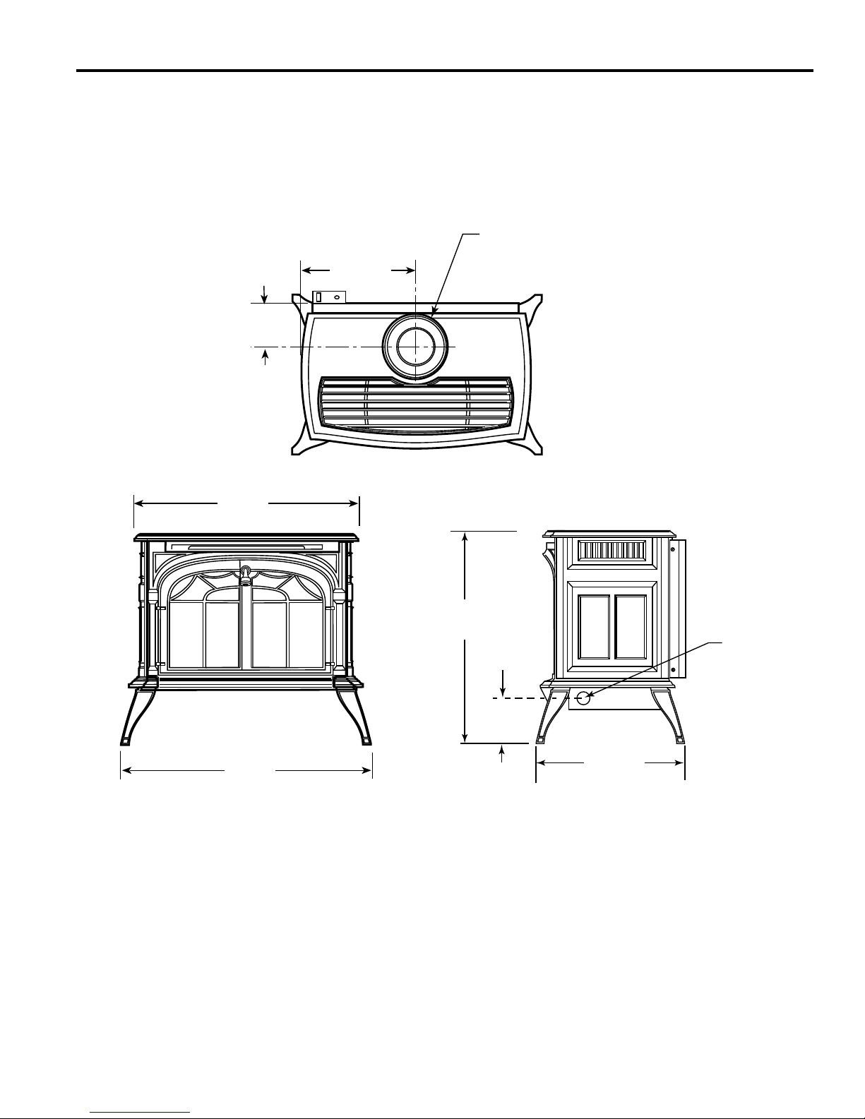
29-3/4"
(758 mm)
31"
(787 mm)
7" Outer Dia.
(178 mm)
Flue Collar
L
C
4-3/4"
(120 mm)
14-7/8"
(378 mm)
RADIANCE
28"
(711 mm)
5"
(127 mm)
18-1/4"
(464 mm)
Supply
Inlet
PRE-INSTALLATION
RADIANCE DIRECT VENT
Weight: Fully assembled; 350 lbs.
STOVE DIMENSIONS
Fig. 1 Radiance dimensions.
20306759
5
Page 6
A
B
E
C
D
PRE-INSTALLATION
INSTALLATION REQUIREMENTS
The installation must conform with local codes or, in the
absence of local codes, with the National Fuel Gas Code,
ANSI Z223.1/NFPA 54 - latest edition. (EXCEPTION: Do
not derate this appliance for altitude. Maintain the manifold pressure at 3.5" w.c. for Natural Gas, and 10" w.c. for
Propane).
In Canada, installation must be in accordance with the
current CSA B-149.1 Installation Codes and/or local codes.
The installation should be done by a qualied service
person who is familiar with the building codes and installation techniques appropriate for your area to accomplish
a safe and effective installation.
Your dealer or your local gas supplier will be able to refer
a qualied service person.
WARNING
Due to high temperatures, the heater should be located
out of trafc and away from furniture and draperies.
The surface of the Heater Is hot when it is in use. Young
children should be watched carefully when they are in
the same room when the Heater is in use, and they
should be taught to avoid the hot surface. Keep any
objects that can burn well away from the Heater, and
observe the recommended clearances that follow.
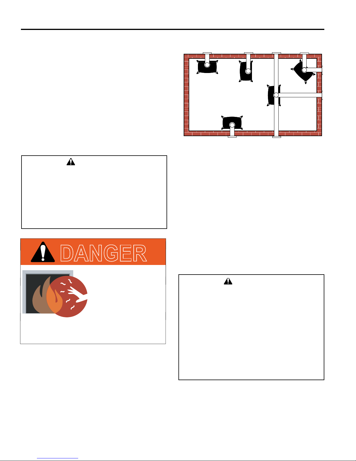
DANGER
Radiance® Direct Vent Gas Heater
Direct Vent System Only
A. Flat on corner wall
B. Room Divider
C. Island
Fig. 2 Possible stove locations.
D. Cross Corner
E. Flat on wall
ST207a
CLEARANCE REQUIREMENTS
Minimum Clearances to Combustible Materials
Measure side clearances as shown in Figures 3, 4 and 5
from the outer edge of the cast iron stove top. Measure
rear clearances from the outermost surface of the steel
rear skirt.
The Radiance heater is approved for installation into an
alcove constructed of combustible materials to the dimensions and clearances shown on the next page.
The same clearances apply in a standard parallel installation.
HOT GLASS WILL
CAUSE BURNS.
WARNING
DO NOT TOUCH GLASS
UNTIL COOLED.
NEVER ALLOW CHILDREN
TO TOUCH GLASS.
A barrier designed to reduce the risk of burns from
the hot viewing glass is provided with this
appliance and shall be installed.
In choosing a location for the stove, consider:
• The location of outside walls;
• Where additional heat is needed:
• Where family members gather most often;
• The vent system requirements.
NOTE: We do not recommend the use of wallpaper
next to this stove. Over time, radiant heat may cause
the wallpaper to shrink, or may adversely affect the
binders in the wallpaper adhesive.
66 20306759
• Always maintain required clearances (air spaces) to
nearby combustibles to prevent re hazard. Do not
ll air spaces with insulation. All venting components
must maintain a 1" (25 mm) clearance to combustible materials. The gas appliance and vent system
must be vented directly to the outside of the building
and never be attached to a chimney serving a separate solid fuel or gas-burning appliance.
• Refer to the manufacturer’s instructions included
with the venting system for complete installation procedures.
Page 7
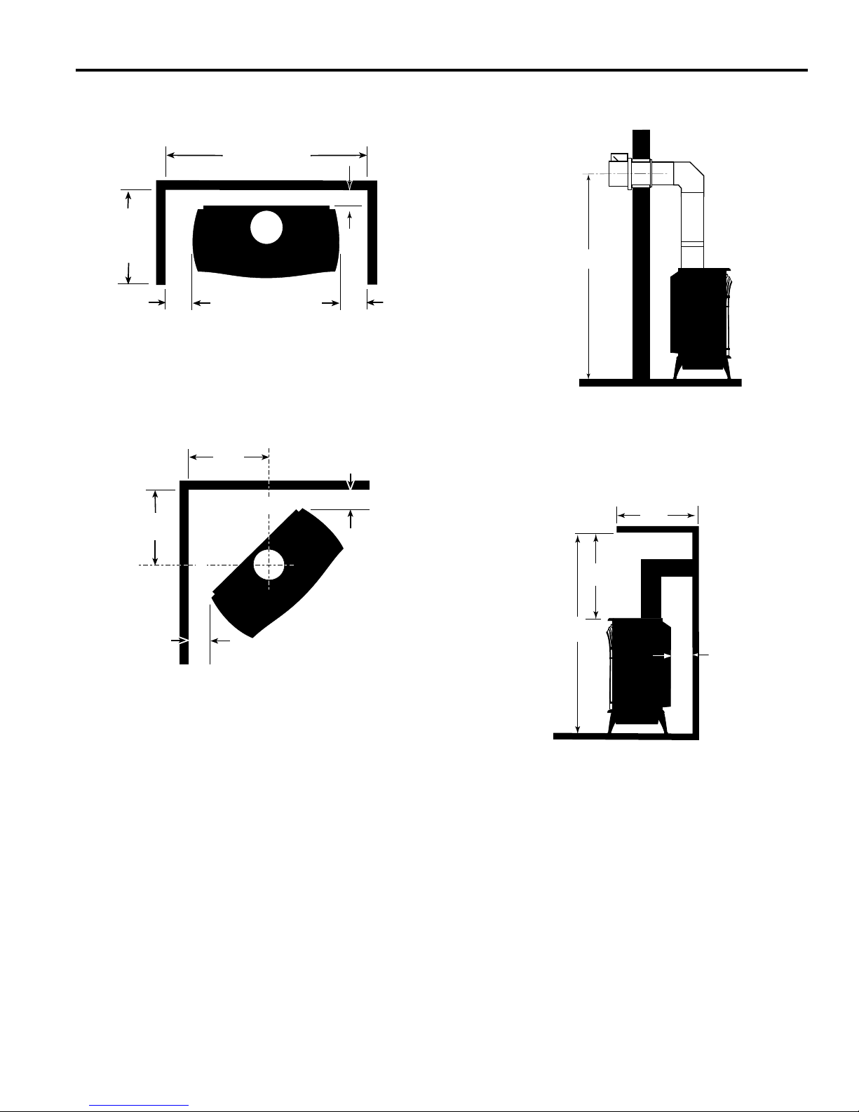
Radiance® Direct Vent Gas Heater
42" (1070mm)
Min. Alcove Width
48"
(1220mm)
Max. Alcove
Depth
6"
(150mm)
6"
(150mm)
4" (102mm)
18"
(457mm)
18"
(457mm)
6"
(150mm)
6"
(150mm)
C
L
C
L
A
A
C
D
B
PRE-INSTALLATION
PARALLEL INSTALLATION
Minimum Clearance and Flue Centerline
ST130
Fig. 3 Parallel installation, minimum back and side clearances,
and ue centerlines.
CORNER INSTALLATION
Minimum Clearance and Flue Centerline
Wall Centerline from Floor
Direct Vent Only
ST131b
A
Effective Minimum
Centerline 57" (1448 mm) (HHT Pipe)
55" (1399 mm) (DuraVent Pipe)
Fig. 5 Minimum wall centerline.
WALL AND CEILING CLEARANCES
Fig. 4 Corner installation, minimum corner clearances and ue
centerline.
ST129
Direct Vent Only
A: Rear Wall 4" (102 mm)
B: Min. Clearance 44" (1118 mm)*
C: Min. Alcove Height 72" (1830 mm)*
D: Max. Alcove Depth 48" (1220 mm)
Sidewall Clearance 6" (150 mm)
*needed for installing DuraVent Minimum Vent Kit #2792 or
HHT Minimum Vent Kit #SLP-FSSK.
Fig. 6 Dimensions and clearances to ceiling or alcove.
ST101b
HEARTH REQUIREMENTS
The Radiance Heater must be installed on rigid ooring.
When the heater is installed directly on any combustible
surface other than wood ooring, a metal or wood panel
extending the full width and depth of the unit must be used
as the hearth. There are no other hearth requirements.
20306759
7
Page 8
20
19
18
16
15
14
13
12
11
10
9
8
7
6
5
4
3
2
1
0
1 2 3 4 5 6 7 8 9 10 11 12 13 14 15 16 17 18 19 20
Vertical Run (in feet)
(Measured from the appliance flue collar to the top of the vent pipe.)
Horizontal Run (in feet)
21
22
23
24
25
26
27
28
29
30
31
32
33
34
35
36
37
38
39
40
ST134b
Radiance
Horizontal
vent run
6/07
PRE-INSTALLATION
Radiance® Direct Vent Gas Heater
GAS SPECIFICATIONS
Max.
Input
Model Fuel Control
RADVT Nat.
RADVT LP
RADVTSC Nat.
RADVTSC LP
Millivolt
Manual
Millivolt
Manual
Signature
Command
Signature
Command
BTU/h
38,000 25,000
36,000 25,000
38,000 25,000
36,000 25,000
GAS INLET AND MANIFOLD PRESSURES
Natural Liquid Propane
Inlet Minimum 5.5" w.c. 11.0" w.c.
Inlet Maximum 14.0" w.c. 14.0" w.c.
Manifold Pressure 3.5" w.c. 10.0" w.c.
The installation of your Vermont Castings stove must
conform with local codes, or in the absence of local
codes, with the National Fuel Gas Code ANSI Z223.1/
NFPA 54 - latest edition, or CSA B149.1 Installation
code. (EXCEPTION: Do not derate this appliance
for altitude up to 2,000 (610 m) for natural gas and
4,500 feet (1,370 m) for LP Gas. Maintain the manifold pressure at 3.5" w.c. for Natural Gas and 10.0"
w.c. for LP Gas.
HIGH ELEVATIONS
Input ratings are shown in BTU per hour and are
certied without deration for elevations up to 2,000
feet (610 m) for natural gas and 4,500 feet (1,370 m)
for LP gas above sea level.
In the USA installations with elevations above 2,000
feet (610 m) for natural gas and 4,500 feet (1,370 m)
for LP gas must be in accordance with the current
ANSI Z223.1/NFPA 54 and/or local codes having
jurisdiction.
In Canada, please consult provincial and/or local
authorities having jurisdiction for installations at
elevations above 2,000 feet (610 m) for natural gas
and 4,500 feet (1,370 m) for LP gas.
Improper installation, adjustment, alteration, service
or maintenance can cause injury or property damage.
Refer to this manual for correct installation and operational procedures. For assistance or additional infor-
mation consult a qualied installer, service agency, or
the gas supplier.
88 20306759
WARNING
Min. Input
BTU/h
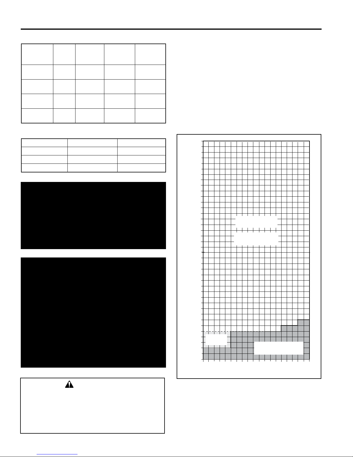
HORIZONTAL TERMINATION
The vent must rise vertically a minimum of 24" (610 mm)
off the top of the unit, before the rst elbow. The horizontal
run may extend up to 20’ (6m) and include a vertical rise
of up to 40’ (12 m). (Figure 7) Horizontal termination must
also meet the criteria shown in Figures 10 through 12.
• Approved vent systems must terminate above and including the heavy line in Figure 7.
• Two 45° elbows may be substituted for each single 90°
elbow.
• With a rise between 2’ - 5’, one 90° or two 45° elbows
may be used.
May use up to
three 90° Elbows
No Restrictor Plate
Required
One 90°
Elbow
Fig. 7 Horizontal vent termination window.
Unacceptable
Venting Conguration
ST134a
Page 9
Radiance® Direct Vent Gas Heater
20
19
18
16
15
14
13
12
11
10
9
8
7
6
5
4
3
2
1
0
20
1 2 3 4 5 6 7 8 9 10 11 12 13 14 15 16 17 18 19
Vertical Run (in feet)
(Measure from the appliance flue collar to the top of the vent pipe.)
Horizontal Run (in feet)
21
22
23
24
25
26
27
28
29
30
31
32
33
34
35
36
37
38
39
40
ST132a
FDV28
Vertical
vent run
12/3/99 djt
PRE-INSTALLATION
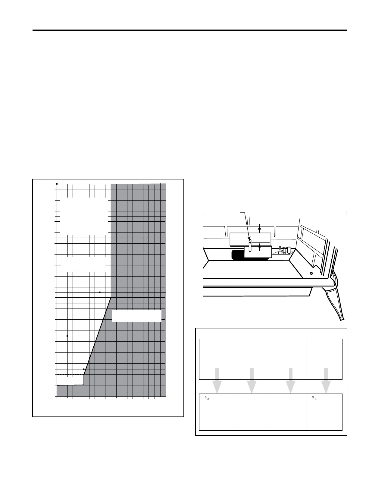
VERTICAL TERMINATION
A vertical vent system must terminate no less than 8’ (2.44
m) and no more than 40’ (12 m) above the appliance ue
collar. A restrictor plate (supplied) must be used, where
specied, in all vertically terminated vent systems. (Refer
to Figure 8) NOTE: The restrictor plate supplied with
the vertical termination should be discarded. Adjust the
restrictor plate according to recommendations in Figure
10. A vertically terminated vent system must also conform
to the following criteria:
• No more than three 90° elbows may be used.
• Two 45° elbows may be substituted for one 90° elbow.
No more than six 45° elbows may be used.
• Vent must rise a minimum of 2 feet (305 mm) before
offset is used.
• Termination height must conform to roof clearance as
specied in Figure 11.
All Vertical Ter-
minations in this
area Require use
of the Restrictor
Plate*
RESTRICTOR PLATE ADJUSTMENT
FOR EXTENDED PIPE RUNS
The Radiance stove is shipped with a restrictor plate in
the Parts Bag. Adjustments can be made by loosening the
adjustment screw to allow the restrictor plate to slide up or
down. (Figure 9) A guide for usage is shown in Figure 10.
NOTE: Some installations may require some adjustment
by the installer for optimum ame appearance. Optimum
ame appearance is a ame that is not subject to tall, dirty
yellow ames producing soot or ames lifting off of the
ember bed ports.
Restrictor Plate Adjustment
• Remove the screw in the back wall of the rebox.
• Install restrictor plate as shown in Figure 9 with cut out
on left side. Secure with adjustment screw.
• Measure from center of screw to top edge of diverter
(Figure 9) to adjust plate according to guidelines in
Figure 10.
• Tighten attachment screw.
• Install logs following log installation instructions.
Adjustment Screw
**No Restrictor
Plate
Fig. 8 Vertical vent termination window.
20306759
Vertical terminations
must be within this
area
Unacceptable
Venting Conguration
**
ST132a
Fig. 9 Loosen screw to adjust restrictor plate.
Examples for Extended Run/Restrictor Plate Settings
Vertical 20’
(6 m), 90°
elbow, out 8’
(2.4 m)
Vertical 11’
(3.4 m), 90°
elbow, out 2’
(610 mm)
Vertical 40’
(12 m)
Vertical 5’
(1.5 m), 90°
elbow, out 5’
(1.5 m)
Restrictor plate measurement from top of plate to
center of screw:
3
⁄4” (70 mm)
2
from center
of screw to
top edge of
plate
Figure 10
Plate down
to top of slot
Plate down
to top of slot
23⁄8” (60 mm)
from center
of screw to
top edge of
plate
ST917
9
Page 10

PRE-INSTALLATION
Radiance® Direct Vent Gas Heater
VENT TERMINATION CLEARANCES
When planning the installation, consider the location of the
vent terminal and clearances. Some of the most common
clearances to keep in mind are shown in Figure 11.
Important: All vent clearances must be maintained.
Check your vent termination clearances against Figures 11 and 12.
The vent should be placed so that people cannot be burned
by accidentally touching the vent surfaces when the stove
is operating.
The vent termination should be located where it cannot be
damaged by such things as automobile doors, lawn mowers
or snowblowers and it should be located away from areas
where it could become blocked by snow, etc.
Some considerations are:
• Obstructions or impediments to venting.
• Nearby combustible materials that could come into contact with combustion exhaust gases.
• Other nearby openings {within 12" (305 mm)} through
which exhaust gas could reenter the building.
• All vegetation within 3’ (76 mm) that may interfere with
the draft.
Other factors that inuence where the installation will be
sited include the location of outside walls, where additional
heat may be desired in the home, where the family members gather most regularly, and perhaps most importantly,
the distance limitations of the venting system.
IMPORTANT
The horizontal termination must not be recessed into
the exterior wall or siding.
Horizontal vent runs must be level toward the vent
termination.
Clearances around the vent termination must be
maintained.
For installations using DuraVent pipe, parallel installations with minimum wall clearance have restricted
access for connecting the Horizontal Vent Cap straps
to the vent pipe. See the maker’s instructions for recommended installation procedures.
Your stove is approved to be vented either through the side
wall, or vertical through the roof.
• HHT does not require any opening for inspection of vent
pipe.
• Only HHT SLP venting components or DuraVent vent-
ing components specically approved and labeled for
this stove may be used.
• Minimum clearances between vent pipes and combustible materials is one (1") inch (25 mm), except where
stated otherwise.
• Venting terminals shall not be recessed into a wall or
siding.
• Horizontal venting must be installed on a level plane
without an inclining or declining slope.
There must not be any obstruction such as bushes, garden
sheds, fences, decks or utility buildings within 24" from the
front of the termination hood.
Do not locate termination hood where excessive snow or
ice build up may occur. Be sure to check vent termination
area after snow falls, and clear to prevent accidental blockage of venting system. When using snow blowers, make
sure snow is not directed towards vent termination area.
LOCATION OF VENT TERMINATION
It is imperative the vent termination be located observing
the minimum clearances as shown in this manual.
1010 20306759
Page 11
Radiance® Direct Vent Gas Heater
V
X
X
X
D
E
B
B
B
C
B
M
B
A
J
K
F
L
VENT TERMINATION AIR SUPPLY INLET
AREA WHERE TERMINAL IS NOT PERMITTED
H
I
Fixed
Closed
Operable
Operable
Fixed
Closed
B
INSIDE
CORNER DETAIL
A
G
CFM145a
V
V
V
V
V
V
V
V
N
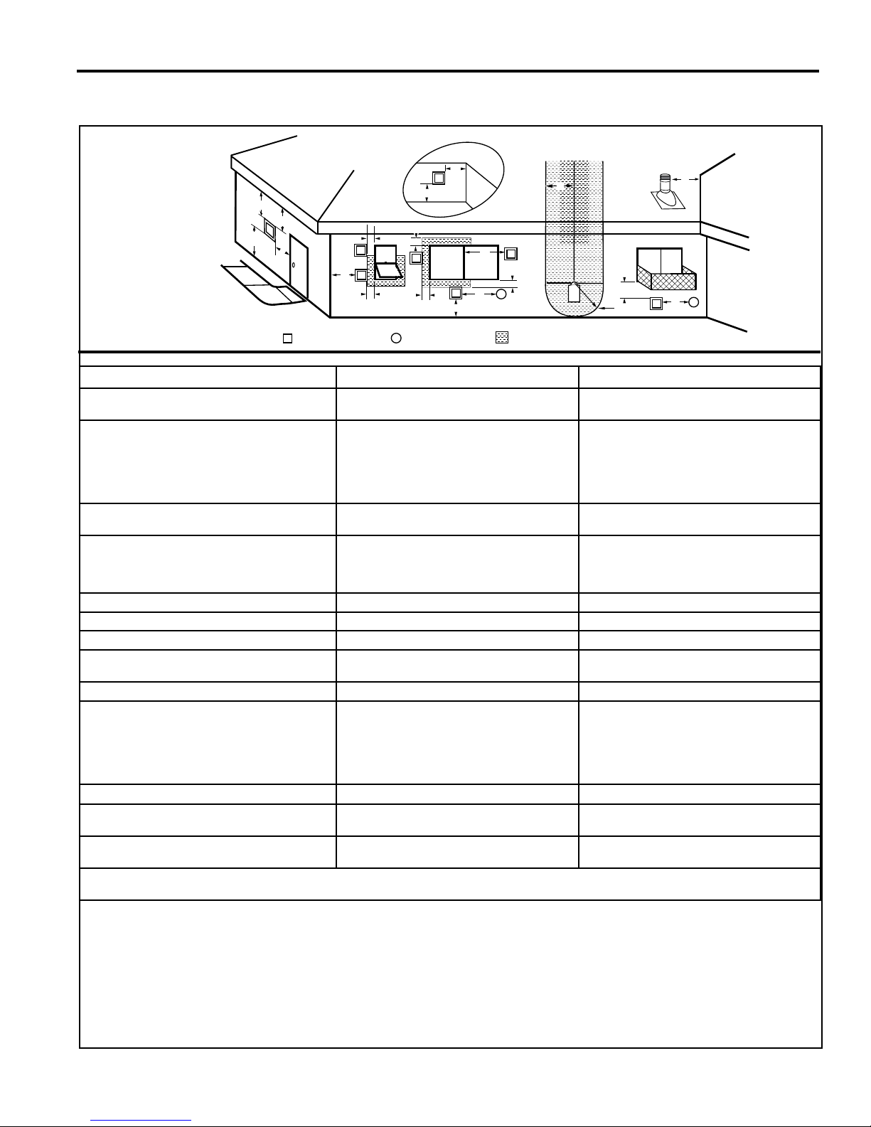
GENERAL VENTING INFORMATION - TERMINATION LOCATION
PRE-INSTALLATION
A = Clearance above grade, veranda, porch, deck
CANADIAN INSTALLATIONS
1
12" (30cm) 12" (30cm)
US INSTALLATIONS
2
or balcony
B = Clearance to window or door that may be
opened
C = Clearance to permanently closed window 12" (305mm) recommended to prevent window
D = Vertical clearance to ventilated soft located
6" (15cm) for appliances <10,000 BTU/h (3kW)
12" (30cm) for appliances >10,000 BTU/h (3kW)
and <100,000 BTU/h (30kW)
36" (91cm) for appliances >100,000 BTU/h
(30kW)
6" (15cm) for appliances <10,000 BTU/h (3kW)
9" (23cm) for appliances >10,000 BTU/h (3kW)
and <50,000 BTU/h (15kW)
12" (30cm) for appliances >50,000 BTU/h
(15kW)
12" (305mm) recommended to prevent window
condensation
condensation
18" (458mm) 18" (458mm)
above the terminal within a horizontal distance
of 2' (610 mm) from the center line of the
terminal
E = Clearance to unventilated soft 12" (305mm) 12" (305mm)
F = Clearance to outside corner see next page see next page
G = Clearance to inside corner see next page see next page
H = Clearance to each inside of center line
extended above meter/regulator assembly
3' (91cm) within a height of 15' (5m) above the
meter/regulator assembly
3' (91cm) within a height of 15' (5m) above the
meter/regulator assembly
I = Clearance to service regulator vent outlet 3' (91cm) 3' (91cm)
J = Clearance to non-mechanical air supply inlet
to building or the combustion air inlet to any
other appliance
6" (15cm) for appliances <10,000 BTU/h (3kW)
12" (30cm) for appliances >10,000 BTU/h (3kW)
and <100,000 BTU/h (30kW)
36" (91cm) for appliances >100,000 BTU/h
(30kW)
6" (15cm) for appliances <10,000 BTU/h (3kW)
9" (23cm) for appliances >10,000 BTU/h (3kW)
and <50,000 BTU/h (15kW)
12" (30cm) for appliances >50,000 BTU/h
(15kW)
K = Clearance to mechanical air supply inlet 6' (1.83m) 3' (91cm) above if within 10' (3m) horizontally
L = Clearance above paved sidewalk or paved
7' (2.13m)
†
7' (2.13m)
†
driveway located on public property
M = Clearance under veranda, porch, deck or
12" (30cm)
‡
12" (30cm)
‡
balcony
N = Clearance above a roof shall extend a minimum of 24” (610mm) above the highest point when it passes through the roof
surface, and any other obstruction within a horizontal distance of 18” (450mm).
1 In accordance with the current CSA-B149 Installation Codes
2 In accordance with the current ANSI Z223.1/NFPA 54 National Fuel
Gas Codes
† A vent shall not terminate directly above a sidewalk or paved
driveway which is located between two single family dwellings and
serves both dwellings
‡ Only permitted if veranda, porch, deck or balcony is fully open on a
minimum 2 sides beneath the oor.
Fig. 11 Vent termination clearances.
20306759
NOTE: 1. Local codes or regulations may require different
2. The special venting system used on Direct Vent
3. HHT assumes no responsibility for the improper
clearances.
Fireplaces are certied as part of the appliance, with
clearances tested and approved by the listing agency.
performance of the appliance when the venting system does
not meet these requirements.
11
Page 12
PRE-INSTALLATION
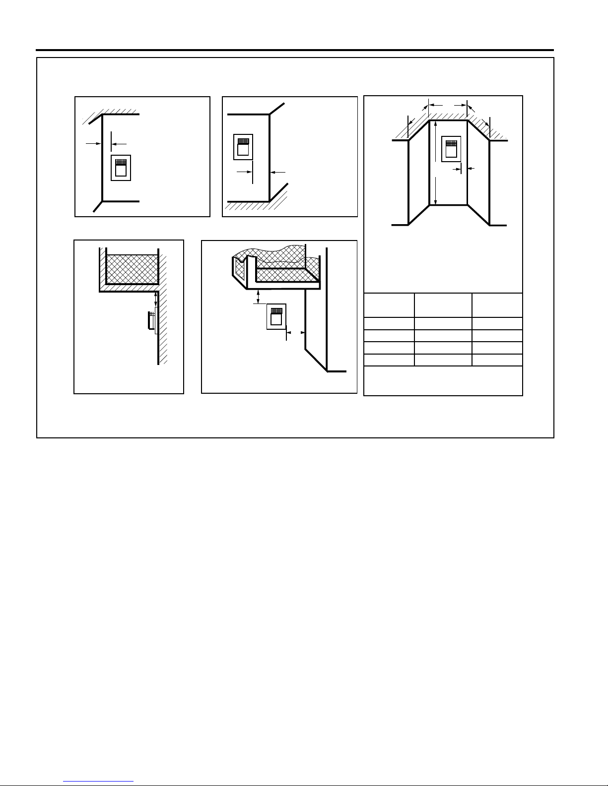
Termination Clearances
Termination clearances for buildings with combustible and noncombustible exteriors.
Inside Corner
G =
G
Combustible
6" (152 mm)
Noncombustible
V
2" (51 mm)
Outside Corner
V
F
F =
Combustible
6" (152 mm)
Noncombustible
2" (51 mm)
Radiance® Direct Vent Gas Heater
Alcove Applications*
C
D
C
V
O
E
Balcony -
with no side wall
V
M =
Combustible &
Noncombustible
12" (305 mm)
*NOTE: Termination in an alcove space (spaces open only on one side and with an overhang) is permitted with the dimensions
specied for vinyl or non-vinyl siding and softs. 1. There must be a 3’ (914 mm) minimum between termination caps. 2. All mechanical air intakes within 10’ (1 m) of a termination cap must be a minimum of 3’ (914 mm) below the termination cap. 3. All gravity
air intakes within 3’ (914 mm) of a termination cap must be a minimum of 1’ (305 mm) below the termination cap.
Fig. 12
TERMINATION CLEARANCES.
Balcony -
with perpendicular side wall
E = Min. 2” (51 mm) for
non-vinyl sidewalls
Min. 12” (305 mm) for
vinyl sidewalls
O = 8’ (2.4 m) Min.
M
Combustible &
Noncombustible
M = 12" (305 mm)
P = 6” (152 mm)
M
V
P
No.
of Caps D
1 3’ (914 mm) 2 x D
2 6’ (1.8 m) 1 x D
3 9’ (2.7 m) 2/3 x D
4 12’ (3.7 m) 1/2 x D
D
= # of Termination caps x 3
Min.
C
= (2 / # termination caps) x D
Max.
C
Min.
Max.
Actual
Actual
Actual
Actual
Actual
584-15
1212 20306759
Page 13
Radiance® Direct Vent Gas Heater
ASSEMBLY AND INSTALLATION
VENTING REQUIREMENTS AND OPTIONS
Approved Vent System Components
The Radiance Heater must be vented to the outdoors
through an adjacent exterior wall or through the roof. The
venting system must be comprised of the appropriate listed
venting components specied on this page. These parts
are available from DuraVent Corporation or your Vermont
Castings Dealer.
See Figure 4 for dimensions relevant to the standard
minimum-vent kits.
HHT Components*
Free Standing Stove Kit w/adj.
Termination Cap, SLP24-BK, SLP6-BK,
SLP6A-BK, SLP90-BK, SLP-WT-BK &
CCSLP
Vertical Termination cap - High Wind
(includes storm collar)
Decorative Wall Thimble Cover SLP-WT-BK
Decorative ceiling restop - black SLP-DCF-BK
Cathedral ceiling support - black SLP-CCS-BK
4" (100mm) pipe length - black SLP4-BK
6" (150mm) pipe length - black SLP6-BK
12" Pipe length-black SLP12-BK
24" Pipe length-black SLP24-BK
36" (915mm) pipe length - black SLP36-BK
48" Pipe length-black SLP48-BK
3"–6" (75 - 150mm) telescoping pipe
extension - black
3"–12" telescoping pipe extension-black SLP12A-BK
45 degree elbow-black SLP45-BK
90 degree elbow-black SLP90-BK
Radiance, Stardance, Oxford SLP adapter CCSLP
*CCSLP adapter is required when using HHT components.
SLP-FSSK
SLP-TVHW
SLP6A-BK
DuraVent Components
Minimum Horizontal Vent Kit 2792
Starter Pipe Assembly (incl. inner &
2768*
outer sections)
90° Elbow, Blk. 46DVA-E90B*
45° Elbow, Gal. 46DVA-E45
6" Straight, Blk. 46DVA-06B*
9" Straight, Blk. 46DVA-09B
11" - 14
5
⁄8" Adjustable Straight Section 46DVA-08AB
12" Straight 46DVA-12
24" Straight 46DVA-24B*
36" Straight 46DVA-36B
48" Straight 46DVA-48
Horizontal Vent Cap 46DVA-HC*
Wall Plate 46DVA-DC
Vinyl Siding Shield 46DVA-VSS
Snorkel Termination - 14" 46DVA-SNK14
Snorkel Termination - 36" 46DVA-SNK30
Wall Strap 46DVA-WS
Cathedral Ceiling Support Box 46DVA-CS
Storm Collar 46DVA-SC
Firestop Spacer 46DVA-FS
Flashing 0/12 - 6/12 46DVA-F6
Flashing 6/12 - 12/12 46DVA-F12
Steel Chimney Conv. Kit A (6
Steel Chimney Conv. Kit B (6
5
⁄8" - 85⁄8") 46DVA-KCA
5
⁄8" -
46DVA-KCB
101⁄2")
Steel Chimney Conv. Kit C (6
5
⁄8" - 13") 46DVA-KCC
Masonry Chimney Conversion Kit 46DVA-KMC
Vertical Termination Cap (High Wind) 46DVA-VCH
Vertical Termination Cap (Low Prole) 46DVA-VC
*Included in Minimum Horizontal Vent Kit #2792
20306759
All DuraVent Straight vent pipe sections have a net length
1
⁄2" (37mm) less than the nominal dimension; i.e., a 6"
1
(152 mm) Straight pipe section has an effective length of
41⁄2" (115 mm).
13
Page 14
ASSEMBLY AND INSTALLATION
ASSEMBLING THE STOVE
Tools Required
• Phillips screwdriver (stub)
• Utility knife
• Metal drill bit: size 28 (.140"/3.5mm)
• Flat-blade screwdriver
• Power drill
• Reciprocating saw
• 9/16" wrench
Parts Bag Contents:
• Three (3) Vent Screws
• Two (2) Switch bracket screws
• Wood handle w/insert lifter (handle for operable door)
• Restrictor Plate
• 4" Starter pipe
• On-Off switch, housing, and wiring harness
• Three (3) Phillips round-head bolts, 1/4"- 20 x 1/2"
• One (1) Tube of Vent Gasket Cement
• Four (4) CS, Hex Hd 3/8-16 x 1 Gr 2-Z
• Four (4) Washer, Fl 3/8-Z
• LP Conversion Kit
• Homeowner’s Installation and Operating Manual
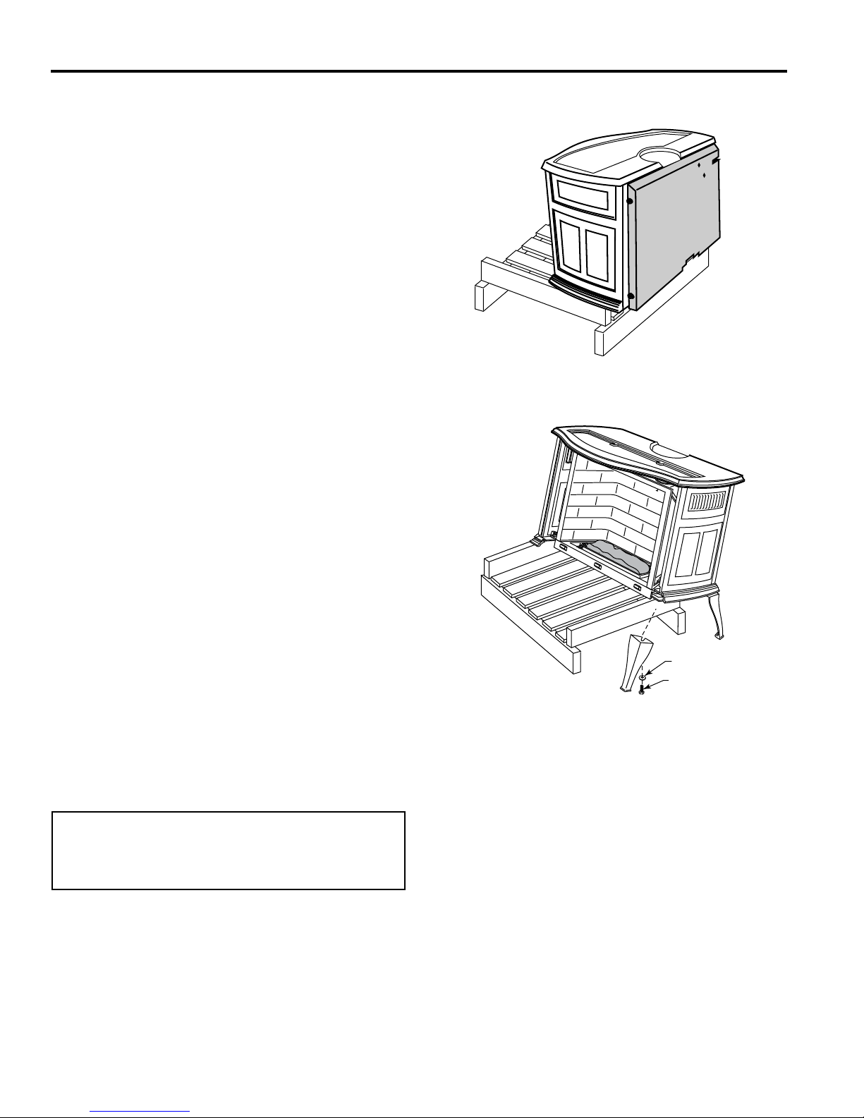
Unpack and Assemble Legs
The Radiance is shipped upright. Cut the shipping straps
before beginning assembly.
1. Slide stove to the rear of the pallet just far enough to
access rear leg holes. Make sure the stove does not
tip over backwards. (Figure 13)
2. Attach the rear legs using 3/8" hex head bolts and
at washer supplied. Tighten with a 9/16" wrench
or socket. Remove and discard the large slot-head
screws using the at-blade screwdriver.
3. Carefully tip the stove onto its rear legs. Adjust the
pallet to allow access to one of the front leg holes. Be
sure to leave the pallet under the stove to prevent the
stove from falling fully forward. (Figure 14)
CAUTION
To prevent valve tubing from being crushed or damaged,
do not rest valve or ignitor on wooden pallet.
Radiance® Direct Vent Gas Heater
ST720
Fig. 13 Slide stove back just far enough to access rear leg holes.
Washer
ST721
Fig. 14 Carefully tip stove onto back legs. Leave pallet under
stove to keep stove from falling fully forward.
4. Have your assistant attach one leg using the hardware described.
5. Move the pallet to allow access to the other front leg
hole. Attach remaining leg.
6. Remove pallet and allow stove to gently rest on all
four legs.
7. Adjust leg levelers to compensate for irregularities in
the hearth.
Hex Head Bolt
1414 20306759
NOTE: Verify the two relief doors (located on top of
the rebox) are properly seated on the gasket. The
doors should sit ush on the gasket, and should
lift easily from the seal around the opening.
Page 15
Radiance® Direct Vent Gas Heater
WARNING
This appliance is equipped with a three-prong (grounded)
plug for your protection against shock hazard and should
be plugged directly into a properly grounded three-prong
receptacle. Do not cut or remove the grounding prong
from this plug.
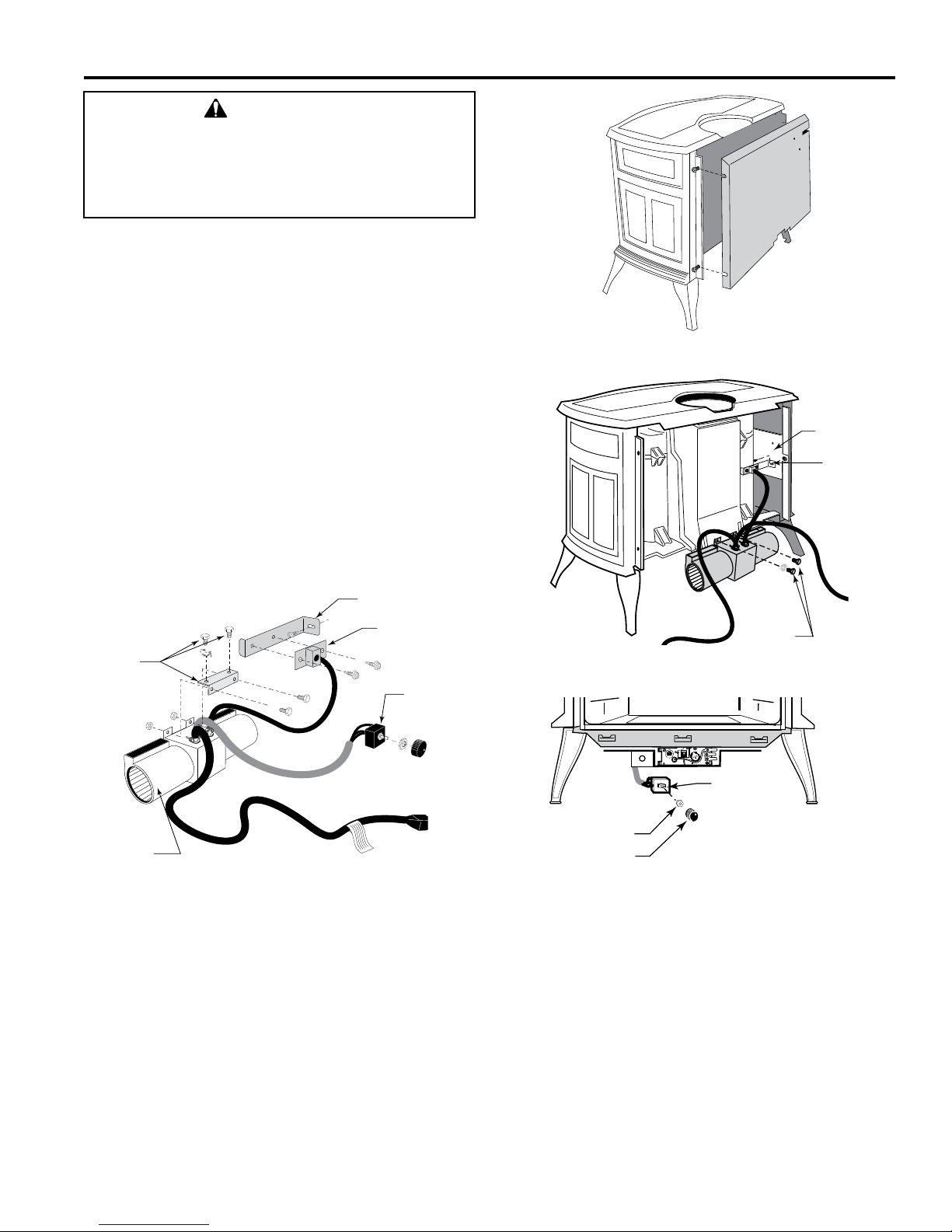
INSTALL THE OPTIONAL FAN - RADVT MODELS
(MILLIVOLT ONLY - SEE PAGE 27 FOR SC MODEL)
If you are installing the optional convection Fan Kit #2767
(FK26), continue here. It is easiest to install fan kit before
connecting gas line.
1. The fan kit includes a Blower Assembly and a Rheostat
Assembly, connected by a cable. (Fig. 15) The Blower
Assembly mounts to the bottom rear of the stove, and
the Rheostat mounts to the valve cover plate. The assembly includes a ‘snapstat’ which automatically turns
the fan On (or Off) above (or below) approximately
109°. The Rheostat also provides a range of fan speed
settings from Off (which overrides the snapstat function) to High. Unpack and inspect the Blower assem-
bly. Conrm that the fan spins freely.
ASSEMBLY AND INSTALLATION
ST147
Fig. 16 Remove rear shroud.
Side Shield
Snapstat
Snapstat
Bracket
Not
Used On
Radiance
Blower
Assembly
ST473a
Fig. 15 Fan kit components.
Snapstat/
Extension
Assembly
Rheostat
Assembly
2. Remove the rear shroud panel (Fig. 16) and fasten
the blower assembly to the rebox back with the two
bolts provided. (Fig. 17)
3. Attach the snapstat assembly to the snapstat bracket with two sheet-metal screws. Attach the snapstat
bracket to the side shield. (Fig. 17)
4. The rheostat control switch attaches to the left side
of the valve bracket at the front of the stove. (Fig. 18)
• Remove retaining nut from shaft of rheostat. (if preinstalled)
Bolts
Fig. 17 Attach blower assembly and snapstat.
Rheostat
Rheostat
Retaining Collar
Rheostat Knob
Fig. 18 Attach the fan rheostat.
ST149
ST347a
• Insert the rheostat through the hole in the back of the
left side of the valve bracket, aligning the locator pin
with the smaller hole in that bracket.
• Thread the retaining nut onto the shaft of the rheostat, tightening with a wrench. Do not overtighten.
• Attach the control knob to the rheostat shaft.
• Use the wire tie to secure the fan and rheostat wire
harnesses together.
20306759
15
Page 16
Outside Wall
Finishing Material
(Vinyl Siding, etc.)
ASSEMBLY AND INSTALLATION
Radiance® Direct Vent Gas Heater
VENTING SYSTEM ASSEMBLY
CAUTION
All HHT Direct Vent Stoves have been tested and
approved to ANSI/CSA Standards and will operate
safely when installed in accordance with this instruction
manual. Read all instructions before starting installation,
then follow these instructions carefully to maximize
stove performance and safety. Report damaged parts
to your dealer.
WARNING
Always maintain minimum clearances around vent
systems. Rear/Top Vent Vertical Side wall: Horizontal
sections of this vent system require a minimum of 3”
(76 mm) clearances to combustibles at the top of the
ue and 1” (25 mm) clearance at the sides and bottom
until the ue penetrates the outside wall. A minimum 1”
clearance all around the ue is acceptable at this point of
penetration. If vertical rise is 71⁄2 feet (2.3 m) or higher
when top venting, the clearance to combustibles is 1” on
all sides of the horizontal run. FOR VERTICAL RUNS
ONLY, maintain a 1” (25 mm) minimum clearance to all
sides. Do not pack the open air spaces around the stove
or ue with insulation or other materials. Any horizontal
run must have a 1/4” rise for every one (1) foot of run
towards the vent termination. Never run the vent level
or down.
• These models are approved to use HHT direct vent
pipe components and HHT termination kits, and DuraVent components. No other venting system components may be used.
• Horizontal runs must be supported every 3 feet (914
mm) using wall straps. Vertical runs must be supported
every 8 feet (2.4 m) using wall straps. Slip wall straps
loosely on to pipe. Attach straps to framing members
using nails or screws. Tighten nut/bolt to secure pipe.
• The stove and venting system should be inspected
before initial use and at least annually by a qualied
eld service person. Inspect the external vent cap on a
regular basis to make sure that no debris is interfering
with the airow. Inspect entire venting system to ensure
proper function.
Failure to follow these instructions may create a possible
re hazard and will void the warranty.
Any common venting of this gas appliance with other
gas appliances is not allowed.
Important Safety Information
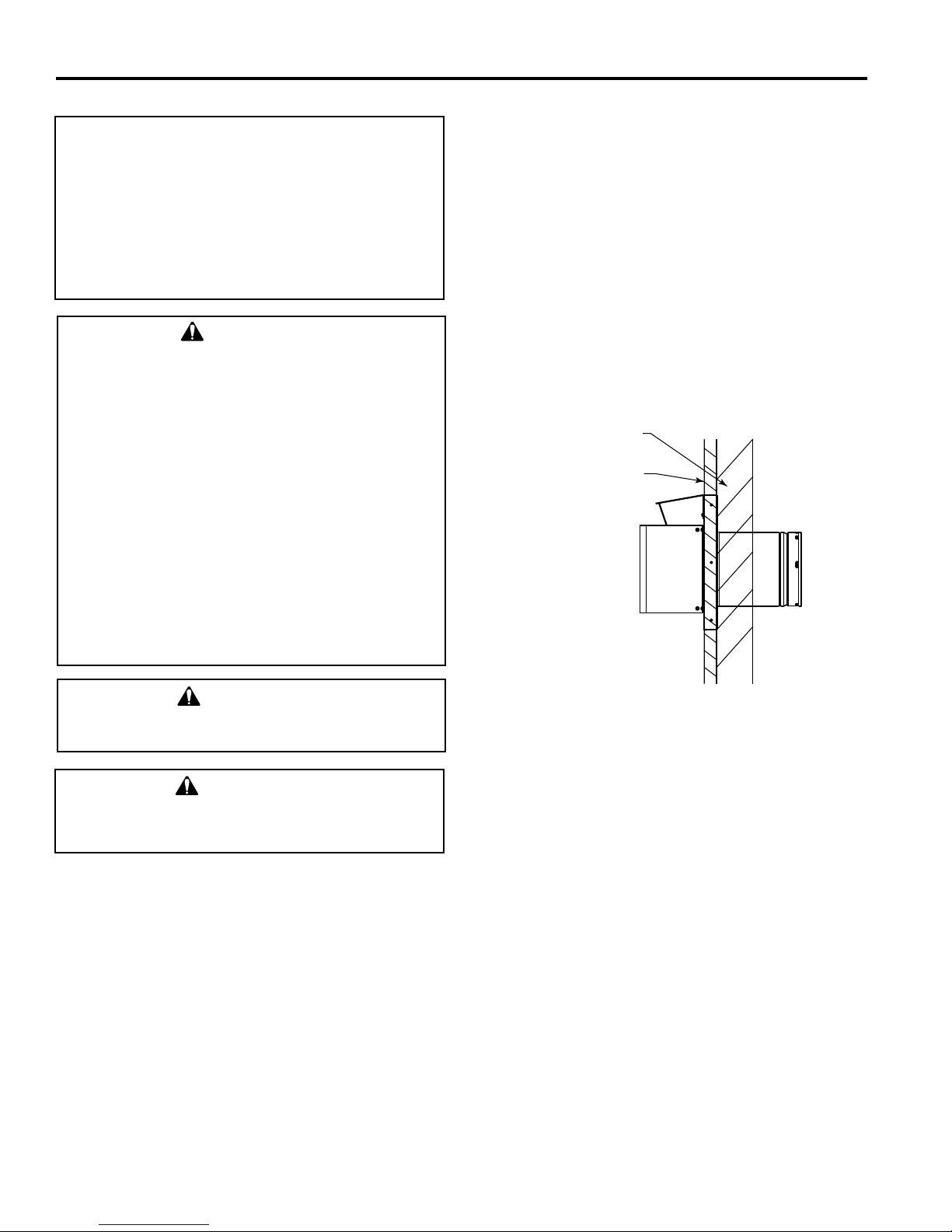
The termination cap MUST be vented directly to the outside. The termination kit MUST NEVER be connected to
a chimney ue(s) servicing a separate solid-fuel burning
appliance or any other appliances.
• Termination cap MUST NOT be recessed into a wall
(see Figure 19).
• The installation must conform with local codes or in
the absence of local codes, with the National Fuel Gas
Code, ANSI Z223.1 (in the United States) or with the
current installation code CSA B149 (in Canada).
WARNING
WARNING
Fig. 19 Termination cap on wall
BEFORE YOU START
Plan your installation. Set the stove in place and survey how
to best vent the unit. Select the appropriate termination kit
and vent pipe for the installation. Read these instructions
and the stove Homeowner’s Manual before beginning
installation. After vent conguration has been decided,
begin attaching pipe to unit.
Items required for installation:
Tools:
Phillips screwdriver Hammer
Saw and/or saber saw Level
Measuring Tape Electric drill and bits
Pliers Square
Building Supplies:
Framing materials
Wall nishing materials
Caulking Material (noncombustible)
1616 20306759
Page 17
Radiance® Direct Vent Gas Heater
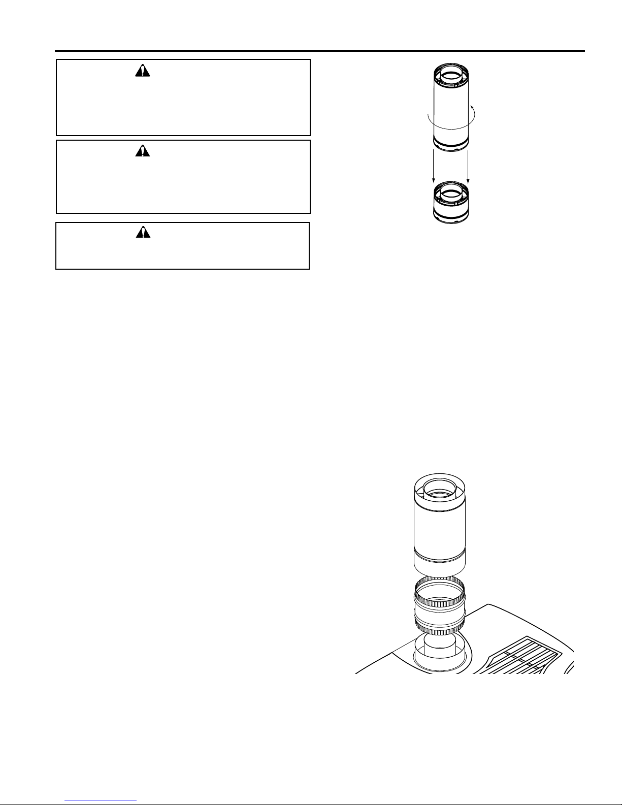
Align
Seams
Rotate
WARNING
Refer to pages 8 and 9 of this manual for the minimum
and maximum venting requirements of your stove and
for approved horizontal vent termination locations prior
to installation. Failure to do so may cause re hazard.
WARNING
Any horizontal run must have a 1/4” rise for every one
(1) foot of run towards the vent termination. Never allow
the vent pipe to run down. This could cause high tem-
peratures and may present a re hazard.
WARNING
Termination cap must be positioned so the embossed
arrow is pointed up.
General Information
The Radiance is approved for installation only with the vent
components listed on page 13. Follow the vent component
instructions exactly.
For U.S. installations: The venting system must conform
with local codes and/or the current National Fuel Gas Code,
ANSI Z223.1/NFPA 54.
For Canadian installations: The venting system must conform to the current CSA B149.1 installation code.
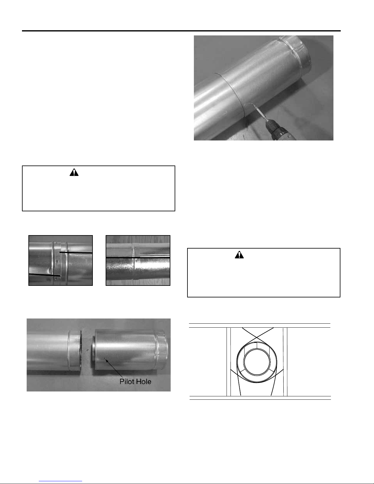
INSTALL THE VENT ADAPTER PIPE
(Vermont Castings SLP Vent Components)
1. Attach Inner Starter Pipe, (found in the Parts Bag), to
the next section of inner pipe.
2. Run a bead of sealant about 1/2" from the upper end
of the Inner starter pipe and join the two sections together.
3. Drill three pilot holes into the Inner Starter and secure
the assembly with three sheet metal screws. (Figure
20)
4. Dry t the Inner Pipe assembly to the stove for the
purpose of determining the center line of the pipe on
the wall.
5. Side Wall Terminations: Dry t the outer elbow with
the vertical outer vent and conrm the centerline
ASSEMBLY AND INSTALLATION
ST211
Fig. 20 Connect the inner starter with the next section of inner
vent pipe.
alignment with the wall thimble opening.
6. Attach the Inner Vent Assembly to the stove.
7. Place a 3⁄8" bead of millpack caulk around the inside
of the cast starter collar. Insert the 65⁄8" outer adapter into the cast outer starting collar and press down
rmly.
8. Install the CCSLP Outer Adapter Pipe.
9. Place a 3⁄8" bead of millpack caulk around the 4"
crimped end of the starter collar on the stove. Attach
the SLP pipe to the adapter, and secure by aligning
adapter and pipe seams, pressing down rmly until
pipe stops, and twisting to lock into place. (Figure 21)
20306759
ST648a
Fig. 21 Attach inner assembly to ue collar.
17
Page 18
ASSEMBLY AND INSTALLATION
ASSEMBLE SLIP SECTIONS
The outer ue of the slip section should slide over the outer
ue of the pipe section and into (inner ue) the last pipe
section (see Figure 23).
Slide together to the desired length, making sure that a
11⁄2" outer ue overlap is maintained between the pipe
section and slip section.
The pipe and slip section need to be secured by driving
two 1/2 in. screws through the overlapping portions of the
outer ues using the pilot holes (see Figure 24).
This will secure the slip section to the desired length and
prevent it from separating. The slip section can then be
attached to the next pipe section.
If the slip section is too long, the inner and outer ues of
the slip section can be cut to the desired length.
WARNING
Risk of Fire/Explosion! DO NOT break seals on slip
sections. Use care when removing termination cap from
slip pipe. If slip section seals are broken during removal
of the termination cap, vent may leak.
Radiance® Direct Vent Gas Heater
Fig. 24 Screws into Slip Section
SECURE THE VENT SECTIONS
Vertical sections of SLP pipe must be supported every 8 ft.
The SLP restop includes tabs that may be used to secure
vertical sections.
The vent support or plumber’s strap (spaced 120° apart)
may be used to secure the vertical sections of pipe (see
Figure 25).
Horizontal sections of vent must be supported every 5 ft
with a vent support or plumber’s strap (see Figure 26).
CORRECT INCORRECT
Fig. 22 Make sure the seams are not aligned to prevent
unintentional disconnection.
Fig. 23 Slip Section Pilot Holes
WARNING
Risk of Fire/Explosion/Asphyxiation! Improper support
may allow vent to sag and separate. Use vent run
supports and connect vent sections per installation
instructions. DO NOT allow vent to sag below connection
point to appliance.
Fig. 25 Securing Vertical Pipe Sections
1818 20306759
Page 19

Radiance® Direct Vent Gas Heater
ASSEMBLY AND INSTALLATION
HORIZONTAL TERMINATION CAP
WARNING
Risk of Fire! The telescoping ue section of the termination cap MUST be used when connecting vent.
• 11⁄2” (38 mm) minimum overlap of vent and telescop-
ing ue section is required.
Failure to maintain overlap may cause overheating and
re.
Fig. 26 Securing Horizontal Pipe Sections
DISASSEMBLE VENT SECTIONS
To disassemble any two pieces of pipe, rotate either section
(Figure 27), so that the seams on both pipe sections are
aligned (Figure 28). They can then be carefully pulled apart.
Fig. 27 Rotate Seams for Disassembly
Note: For horizontal vent runs through a combustible wall and framing dimensions, refer to appliance
installation manual.
Install the Horizontal Termination Cap
Attach slip section of cap to last vent section. Maintain 11⁄2"
overlap between slip and vent sections.
Note: For installations using black pipe, slide the
decorative wall thimble over the last vent pipe
before connecting the termination to the pipe.
When this connection has been made, slide the
wall thimble up to the interior wall surface and
attach with screws provided.
Secure termination cap to exterior wall using provided
holes and fasteners.
Vent termination must not be recessed in the wall. Siding
may be brought to the edge of the cap base.
CAUTION
Risk of Burns! Local codes may require installation of a
termination guard to prevent anything or anyone from
touching the hot cap.
Fig. 28 Align and Disassemble Vent Sections
20306759
Flash and seal as appropriate for siding material at outside
edges of cap.
When installing a horizontal termination cap, follow the cap
location guidelines as prescribed by current ANSI Z223.1
and CAN/CGA-B149 installation codes.
19
Page 20

ASSEMBLY AND INSTALLATION
Radiance® Direct Vent Gas Heater
DIVERT ROOF RUN-OFF
HHT recommends, where excessive water run-off is
possible, use of one of the two options shown in Figure
29 to prevent water running off the roof and onto/into the
horizontal termination cap.
Install gutter
Vent Opening for Combustible Walls
9"
(244 mm)
9"
(244 mm)
Stove Hearth
Opening for Noncombustible Wall
7"
(190 mm)
Stove Hearth
Fig. 30 Locate Vent Opening on Wall
Framing Detail
2. Secure restop to the inside frame, center in the 9" x
9" vent opening.
3. Place stove into position. Measure the vertical height
(X) required from the base of the ue collars to the
center of the wall opening. Figure 31
Install L-shaped
diverter
Fig. 29 Locate Vent Opening on Wall
VERTICAL SIDE WALL INSTALLATION
NOTE: For all top vent vertical through-the-roof
installations, install the supplied ue restrictors
onto the top edge of the firebox flue adapter
according to the Vertical Side wall Installation Flue
Restrictor Chart.
1. Locate vent opening on the wall. It may be necessary
to rst position the stove and measure to obtain hole
location. Depending on whether the wall is combus-
tible or noncombustible, cut opening to size. Figure
30 (For combustible walls rst frame in opening.)
Combustible Walls: Cut a 9"H x 9"W (244 x 244 mm) hole
through the exterior wall and frame as shown. Figure 30
Noncombustible Walls: Hole opening must be 7" (178
mm) in diameter.
X
Fig. 31 Vertical Height Requirements
4. Using appropriate length of pipe section(s) attach to
stove by twisting collar.
5. Measure the horizontal length requirement including
a 2” (51 mm) overlap, i.e. from the elbow to the outside wall face plus 2” (51 mm) (or the distance required if installing a second 90° elbow). Figure 32
NOTE: When using ex vent, the opening will have
to be measured according to the 1/2” (13 mm) rise
in 12” (305 mm) vent run.
2020 20306759
NOTE: Always install vertical side wall horizontal
venting with a 1/4" rise for every 12" of run.
Page 21

Radiance® Direct Vent Gas Heater
ASSEMBLY AND INSTALLATION
6. Use appropriate length of pipe sections – telescopic
or xed – and install. The sections which go through
the wall are packaged with the starter kit, and can be
cut to suit if necessary.
5
7. Guide the vent terminations 4" and 6
⁄8" collars into
their respective vent pipes. Double check that the
vent pipes overlap the collars by 2" (51 mm). Secure
the termination to the wall with screws provided and
caulk around the wall plate to weatherproof. As an
alternative to screwing the termination directly to the
wall, you may also use expanding plugs or an approved exterior construction adhesive.
X
Fig. 32 Horizontal Length Requirement
FP1182
NOTE: Support horizontal pipes every 5' (152 cm)
with metal pipe straps.
VENT TERMINATION BELOW GRADE
Install Snorkel Kit #SLP-SNORK when it is not possible to
meet the required vent termination clearances of 12" (305
mm) above grade level. The snorkel kit will allow installation
depth of down to 7" (178 mm) below grade level. The seven
inches is measured from the center of the horizontal vent
pipe as it penetrates the wall. If the venting system is
installed below grade, a window well must be installed
with adequate and proper drainage. (Figure 35)
NOTE: Be sure to maintain side wall clearances
and vent run restrictions. Refer to Page 7, Figures
3, 4, 5, 6.
1. Establish the vent hole through the wall.
2. Remove soil to a depth of approximately 16" (406
mm) below the base of the snorkel. Install a window
well (not supplied). Rell the hole with 12" (305 mm)
of coarse gravel and maintain a clearance of at least
4" (102 mm) below the snorkel. (Figure 35)
3. Install the vent system as described on Pages 16-18.
4. Be sure to make a watertight joint around the vent
pipe joint at the inside and outside wall joints.
5. Apply high temperature sealant around the inner and
outer snorkel collars. Join the pipes and fasten the
snorkel termination to the wall with the screws provided.
6. Level the soil to maintain a 4" clearance below the
snorkel.
7. If the foundation is recessed, use extension brack-
ets (not supplied) to fasten the lower portion of the
snorkel. Fasten the brackets to the wall rst, and then
fasten to the snorkel with self-tapping #8 x 1/2" sheet
metal screws. Extend the vent pipes out as far as the
protruding wall face. (Figure 35)
Cutout On Vinyl
Termination Cap
Fig. 33 Horizontal Termination Cap on a Vinyl Siding Wall
20306759
Vinyl Siding Wall
Recessed Wall
Firestop
Sheet Metal
Screws and
Bracket
Wall Screws
and Anchors
Waterproof Seal
Around Pipe
ST219
Fig. 34 Use extension brackets to mount snorkel against
recessed wall.
Finishing
Collar
7" Pipe
Wall Plate
21
Page 22

RADIANCE
ASSEMBLY AND INSTALLATION
Radiance® Direct Vent Gas Heater
Wall Screws
and Anchors
Snorkel
Termination
Cap
4" Clearance
Gravel
Drain
Window Well
Fig. 35 Snorkel kit installation.
Waterproof Seal
Around Pipe
Firestop
list.)
• The maximum angular variation allowed in the system
is 270°. Figure 39
• For the minimum height of the vent above the highest
point of penetration through the roof refer to Figure 39�
Vertical Through-the-Roof Installation
Flue Restrictor Setting Chart
Vertical Run Restrictor Setting
8-12 feet of pipe Medium restriction
(2.4 – 3.7 m) Figure 36
12-40 feet of pipe Maximum restriction
(3.7 – 12 m) Figure 37
ST653
VERTICAL THROUGH-THE-ROOF
APPLICATION/INSTALLATION
For all vertical through-the-roof installations, the supplied
ue restrictors must be installed. Install the ue restrictor
according to the settings shown in the Vertical Through-theRoof Installation Flue Restrictor Chart in order to balance
the airow in and out of the unit and to maintain proper
ame height.
This gas stove has been approved for:
• Vertical installations up to 40' (12 m) in height. Up to
a 10' (3 m) horizontal vent run can be installed within
the vent system using a maximum of two 90° elbows.
Figure 38
• Up to two 45° elbows may be used within the horizontal
run. For each 45° elbow used on the horizontal plane,
the maximum horizontal length must be reduced by
18" (450 mm).
Example: Maximum horizontal length:
No elbows = 10' (3 m)
1 x 45° elbow = 8.5' (2.6 m)
2 x 45° elbows = 7' (2.1 m)
• A minimum of an 8' (2.5 m) vertical rise is required.
(Figure 38)
• Two sets of 45° elbow offsets may be used within the
vertical sections. From 0 to a maximum of 8' (2.5 m) of
vent pipe can be used between elbows. Figure 38
• SLP-HVS supports offsets. This application will require
that you rst determine the roof pitch and use the appropriate starter kit. (Refer to Venting Components
FP3042
Fig. 36 Flue Restrictor Set at Medium Restriction
FP3043
Fig. 37 Flue Restrictor Set at Maximum Restriction
2222 20306759
Page 23

Radiance® Direct Vent Gas Heater
Horizontal
overhang
12
X
20 in.
(508 mm)
Lowest
Discharge
Opening
Termination
Cap
Roof Pitch
is X / 12
Vertical
wall
H (min.) - Minimum height
from roof to lowest
discharge opening.
24 in. min.
(610 mm)
Roof Pitch H (Min.) Ft. Roof Pitch H (Min.) Ft.
Storm Collar
Roof
Flashing
Storm Collar
Vertical Termination
24 in. min.
(610 mm)
Termination
Cap
ASSEMBLY AND INSTALLATION
Horizontal
overhang
20 in.
(508 mm)
Lowest
Discharge
Opening
Vertical
wall
Firestop
Spacer
Flashing
Offset
Support Collar
Storm Collar
Roof
Flashing
H (min.) - Minimum height
from roof to lowest
discharge opening.
Flat to 6/12 1.0* Over 11/12 to 12/12 4.0
Over 6/12 to 7/12 1.25* Over 12/12 to 14/12 5.0
Over 7/12 to 8/12 1.5* Over 14/12 to 16/12 6.0
Over 8/12 to 9/12 2.0* Over 16/12 to 18/12 7.0
Over 9/12 to 10/12 2.5 Over 18/12 to 20/12 7.5
Over 10/12 to 11/12 3.25 Over 20/12 to 21/12 8.0
* 3 ft. minimum in snow regions
X
12
Roof Pitch
is X / 12
Fig. 39 Minimum Height from Roof to Lowest Discharge Opening
Plate
Figure 38. Typical Vertical Venting Conguration
Ceiling Support CollarCeiling Support
Trim Plate
20306759
23
Page 24

ASSEMBLY AND INSTALLATION
INSTALL LOG SET
Before beginning log installation, remove stove front and
glass frame. Refer to Figures 40 and 41.
Note: Remove the safety barrier before you remove
the glass frame. To remove the barrier, simply lift
up and pull out until the tabs are clear of their
corresponding slots on the rebox. Then proceed
to remove the glass frame by following the steps
below.
Radiance® Direct Vent Gas Heater
DANGER
HOT GLASS WILL
CAUSE BURNS.
DO NOT TOUCH GLASS
UNTIL COOLED.
NEVER ALLOW CHILDREN
TO TOUCH GLASS.
A barrier designed to reduce the risk of burns from
the hot viewing glass is provided with this
appliance and shall be installed.
Fig. 40 Remove the safety barrier and stove front.
Fig. 41 Release the latches to remove the glass frame.
ST139
ST141
2424 20306759
Page 25

Radiance® Direct Vent Gas Heater
ASSEMBLY AND INSTALLATION
Before installation, inspect ember bed burner for damage.
Do not use ember bed if damaged or cracked. Small, shallow surface cracks are acceptable.
1. Remove the logs from their packaging and inspect
each piece for damage. DO NOT INSTALL DAMAGED LOGS.
2. Install the rear log by placing it on the ember bed
toward the back of the rebox. (Figure 42) The log
should touch the back wall of the rebox. When the
log is in place, the two (2) notches on the bottom of
the log rest on the two (2) ribs on the back side of the
ember bed. (Figure 43)
Fig. 42 Rear Log
Ribs for Rear Log
Rear Log
LG488
Ember Bed
3. Install the front left and right logs (Figure 44) by placing them on the ribs shown in Figure 43. Make sure
the logs line up with the at spots on the ember bed
intended for location purposes. (Figure 43)
4. Install the left cross log by engaging the hole on the
bottom with the pin on the left side of the rear log. Set
front side of cross log on notch in ember bed. (Figure
45)
5. Install the right cross log by engaging the hole on the
bottom with the pin on the right side of the rear log.
Set front edge of cross log on ember bed as shown
in Figure 45.
LG489
Front Right Log
Front Left Log
Fig. 44 Front Logs
Rib Flat Spot for
Front Left Log
Fig. 43 Ribs for Logs
Rib and Flat Spot
for Front Right Log
LG487
Left Cross
Log
Front Left Log
Fig. 45 Completed Installation
Rear Log
Right
Cross Log
Front
Right Log
LG490
Ember Bed
20306759
25
Page 26

P
I
L
O
T
TPTH
TP
TH
ASSEMBLY AND INSTALLATION
Radiance® Direct Vent Gas Heater
INSTALL ON/OFF SWITCH - RADVT MODELS
The switch assembly parts are found in the parts bag.
1. Attach switch assembly to left rear side of stove
shroud (when facing shroud) using two screws and
existing holes in shroud. (Figure 46)
2. Run wires down back of stove, under bottom of rear
shroud to valve.
3. Attach wires to valve terminals. (Figure 47)
Switch Assembly
Screws
Fig. 46 Attach switch assembly to rear shroud.
Existing
Holes
ST315
SIGNATURE COMMAND® SYSTEM
General
RADVTSC models are equipped with the Signature Command control valve (Figure 48) which operates on 6 volts.
The A/C module plugs into the stove junction box A/C power
supply. Four (4) “AA” batteries are used for back up during
power outages.
The Signature Command System can also be operated
without A/C power. The system can run on four (4) “AA” batteries for approximately six (6) months under normal use.
A/C power must be used to power the A/C module and
blowers.
Pressure Inlet
Valve
SIT VALVE
Thermopile
ON/OFF Switch or
Millivolt Thermostat
Fig. 47 Install wiring to switch before connecting to valve.
Pressure Outlet
Fig. 48 Signature Command Valve
FP1622
FP1909a
Pilot Adjustment Screw
WARNING
THERMOSTAT OR WALL SWITCH
CONNECTION (OPTIONAL)
Use only a thermostat rated for 500 - 750 millivolts.
Check the table below for the appropriate gauge thermostat
wire to use for the length of lead required in your installation.
Thermostat
Wire / Gauge Maximum Run
18 20 feet
16 20 - 40 feet
14 up to 60 feet
1. Install the wall thermostat or switch in the desired
location and run the wires to the stove location. Terminate these leads with 1/4" female connectors.
2. Connect the thermostat wires to the valve. (Figure
2626 20306759
47)
Electrical connections should only be performed by a
qualied, licensed electrician. Main power must be off
when connecting to main electrical power supply or
performing service. All wiring shall be in compliance
with all local, city and state codes. The appliance, when
installed, must be electrically grounded in accordance
with local codes or in the absence of local codes, with the
National Electrical Code ANSI/NFPA 70 (latest edition)
and Canadian Electrical Code, CSA C22.1.
CAUTION
Label all wires before disconnecting when servicing
controls. Wiring errors can cause improper and dangerous operation.
Page 27

Radiance® Direct Vent Gas Heater
ASSEMBLY AND INSTALLATION
JUNCTION BOX WIRING
This should be done before framing the stove. Wire the
receptacle into an electrical circuit. Wire with minimum
60° C wire in accordance with prevailing codes.
Remove the external junction box cover by removing the
screw from the side of the outside rebox wall. Junction
box was installed at the factory.
The junction box cover has a factory installed “romex” style
strain relief connector. After connecting the wires, route
the wire leads through this connector. Refer to the wiring
diagram in Figure 49.
120V AC
60Hz
Factory Supplied
Not Supplied
Junction Box
Fig. 49 Junction Box Wiring Diagram
COMMAND CENTER WALL INSTALLATION
The command center may be mounted on the wall with
the use of the SCSWEK Kit (15ft. cable, junction box, wall
cover).
Mount the junction box provided at the desired location on the wall. Do not extend beyond the 15 ft.
wire cable provided. If a longer distance is required,
the 15 ft. may be extended up to 30 ft. maximum by
using two (2) SCSWEK cables plugged together.
Route the wire from junction box to lower control area
at bottom of stove. Unplug the 12" cable from the command center. Attach the connector to the pins from wire
by pushing in to connector making sure to follow the color
code on connector. Plug the 15 ft. extension cable into
the 2 ft. cable. Remove command center from the stove
and plug the other end of the extension cable into the
command center. Snap on wall cover provided and screw
to junction box.
CAUTION
Electrical connections should only be performed by a
qualied, licensed electrician. Main power supply must
be turned off before connecting fans to the main electrical power supply or performing service.
WARNING
Electrical Grounding Instructions: This appliance is
equipped with a three-prong (grounding) plug for your
protection against shock hazard and should be plugged
directly into a properly grounded three-prong receptacle.
Install the Fan - RADVTSC Models
It is easiest to install the fan kit before connecting a gas line.
• Unpack and inspect the blower assembly. Conrm
that the fan spins freely.
• Unfasten the two machine bolts attached to the lower
back of the stove. Figure 51
• Using the two bolts secure the blower assembly to
the rear of the stove. Figure 51
• Connect the blower wires to the wire control board.
See Figure 53 on page 29.
ST473aED
Blower
Assembly
Fig. 50 RADVTSC Blower assembly
WALL SWITCH INSTALLATION
The wall switch wire connection is located off the 2 ft. wire
harness from the control box to the command center. Figure
52. The connection is labeled “Wall Switch”. Unplug the
male and female connectors and connect the two (2) low
voltage wires provided. Run wire to desired location on
wall. Up to 50 ft. of 18 ga. wire may be used if necessary.
Attach wires to wall switch. Mount the wall switch in to
junction box and screw on cover.
WARNING
Do not connect wall switch to 110 V circuit.
20306759
ST147
Fig. 51 Secure Blower assembly to lower back of the stove.
27
Page 28

ASSEMBLY AND INSTALLATION
Radiance® Direct Vent Gas Heater
CONNECT THE GAS SUPPLY LINE
Check the Rating Plate attached by a steel cable to the
rebox, to conrm that you have the appropriate rebox for
the type of fuel to be used. The Radiance may be converted
from one gas to another using the appropriate Fuel Conversion Kit listed in this manual under Replacement Parts.
In the U.S.; Gas connection should be made in accordance
with current National Fuel Gas Code, ANSI Z223.1/NFPA
54. Since some municipalities have additional local codes,
be sure to consult your local authority.
In Canada; consult the local authority and CSA-B149.1
installation code.
NOTE: Always check for gas leaks with a mild soap
and water solution. Do not use an open ame for
leak testing.
Light the pilot according to the directions in the Operation
section of this manual.
BURNER INFORMATION
The appliance must only use the gas specied on the rating
plate, unless converted using a Vermont Castings Fuel
Conversion Kit. To convert from Natural Gas to LP use Kit
20012729 or 20012900. To convert from LP to Natural Gas
use Kit 20012899 or 20012902.
Conversion instructions are provided with each kit and in
this manual.
CAUTION
This appliance should only be connected by a qualied
gas technician. Test to conrm manifold pressures as
specied below.
The Radiance Heater and its individual shutoff valve
must be disconnected from the gas supply piping during
any pressure testing of that system at test pressures in
excess of 1/2 psig (3.5 kPa).
The Radiance Heater must be isolated from the gas
supply piping system by closing its individual manual
shutoff valve during any pressure testing of the gas
supply piping system at test pressure equal to or less
than 1/2 psig.
There must be a gas shutoff between the stove and
the supply.
In order to connect Natural Gas, use a tting with 1/2"
NPT on the valve side and 1/2" natural gas supply line
with an input of 38,000 BTUs at a manifold pressure
of 3.5" between minimum inlet supply of 5.5" w.c. and
maximum of 14.0" w.c.
In order to connect Propane, use a tting with 1/2" NPT
on the valve side and 1/2" propane gas supply line
with an input of 36,000 BTUs at a manifold pressure of
10.0" between a minimum inlet supply of 11.0" w.c. and
maximum of 14.0" w.c.
THIS APPLIANCE SHOULD BE CONNECTED TO THE GAS SUPPLY ONLY BY A QUALIFIED GAS
SERVICE TECHNICIAN. FOLLOW ALL LOCAL CODES.
THERE MUST BE A GAS SHUT-OFF BETWEEN THE STOVE AND THE SUPPLY.
2828 20306759
Page 29

Radiance® Direct Vent Gas Heater
SIGNATURE COMMAND WIRING DIAGRAM
ASSEMBLY AND INSTALLATION
Pilot
TO JUNCTION BOX
IN FIREPLACE
WHITE
Opt. Blower
BLACK
BLACK
Opt. Aux.
WHITE
300 Watt
Max.
NOTE: Wall switch wires
must be connected together
if a wall switch is not being used.
GREEN
PLUG-IN
CONNECTOR
Ground
Plug-in Connector
Control Board to
Solenoid
Gas In
A/C MODULE
Control Board
Conversion
NG/LP
Plug-in Connector
Stepper Motor to
Control Board
DC Power/Green
RF Receiver
ON/OFF Button
Black / Thermopile
Red / Thermopile
Sensor
Ignitor / Sparker
Plug-in Connector
Control Board to Command Center
OFF/LO
LED
ON/HI
Master Switch
Command Center
Gas Out
Optional
Wall Switch
Fig. 52 Signature Command Wiring Diagram
To Junction Box
In Fireplace
Fig. 53 Blower Wiring Diagram
BLACK
WHITE
Optional
AUX
Light
Valve
{
{
WHITE
BLACK
BLACK
WHITE
GREEN
Pilot Gas Tubing
Connector
Pin To Contro l Box
20306759
29
Page 30

ASSEMBLY AND INSTALLATION
INSTALL THE SAFETY BARRIER
CERTIFIED
SAFETY BARRIER
NOTE: A barrier designed to reduce the risk of
burns from the hot viewing glass is provided
with this appliance and shall be installed for the
protection of children and other at risk individuals. If the barrier becomes damaged, the barrier shall be replaced with the manufacturer's
barrier for this appliance.* Any safety screen,
guard, or barrier removed for servicing the
appliance must be replaced prior to operating
the appliance.
* See parts list for model number�
The safety barrier has been designed to work with the
doors open or closed.
1. Remove screen from packaging.
2. Place the two bottom hooks over the bottom
edge of the stove opening Figure 54
3. Press the screen against the stove snapping the
two spring ngers until the screen ts securely
in place.
Radiance® Direct Vent Gas Heater
Bottom
Hooks
Fig. 54 Install safety barrier screen.
WARNING
The safety screen barrier must be installed after the
glass front is in place. It is not a replacement for the
glass and the unit must not be operated without the
glass in place.
INSTALL THE MESH AND GRILLE
Place the mesh and grille on the top of the Radiance stove
to complete assembly.
NOTE: It is the responsibility of the installer to
ensure the barrier is afxed to the stove at the time
of installation.
DANGER
HOT GLASS WILL
CAUSE BURNS.
DO NOT TOUCH GLASS
UNTIL COOLED.
NEVER ALLOW CHILDREN
TO TOUCH GLASS.
A barrier designed to reduce the risk of burns from
the hot viewing glass is provided with this
appliance and shall be installed.
3030 20306759
Page 31

Radiance® Direct Vent Gas Heater
L
O
H
I
Turn
counterclockwise
to increase
flame height
Turn clockwise
to decrease
flame height
OPERATING INSTRUCTIONS
OPERATION
The Radiance is operated with the front plate in place with
the doors open or closed. To open the front doors, pull
forward to separate the magnetic catch. Ensure the safety
barrier screen is in place during operation.
YOUR FIRST FIRE
Read these instructions carefully and familiarize yourself
with the burner controls shown on Page 32 (RADVT
models) or page 35 (RADVTSC models). Locate the pilot
assembly, Figure 56. Follow the lighting instructions in this
manual exactly.
During the rst re, it is not unusual to smell some odor
associated with new logs, paint and metal being heated.
Odors should dissipate within the rst eight to ten hours,
however, you can open a window to provide fresh air to
alleviate the condition.
PILOT AND BURNER INSPECTION
Each time you light your heater check that the pilot ame
and burner ame patterns are as shown in Figure 55. If
ame patterns are incorrect, turn the heater off. Contact
your dealer or a qualied gas technician for assistance.
Do not operate the heater until the pilot ame is correct.
Follow regular maintenance procedures as described in the
Cleaning and Maintenance section of this manual.
FLAME CHARACTERISTICS
It is important to periodically perform a visual check of the
pilot and the burner ames. Compare them to Figure 56. If
any of the ames appear abnormal, call a service person.
RADVT MODELS
Sensor
Thermopile
Pilot Assembly
Fig. 55 Pilot Assembly location.
20306759
ST476
RADVTSC MODELS
Figure 56 Correct pilot and burner ame appearance.
FP2453
FLAME & TEMPERATURE ADJUSTMENT
For RADVT models which are equipped with HI/LO valves,
ame adjustment is accomplished by rotating the HI/LO
adjustment knob located near the center of the gas control
valve. (Figure 57)
Figure 57 Flame adjustment knob for SIT valve.
31
Page 32

PILOT
ON
OFF
ON
P
I
L
O
T
O
F
F
O
F
F
OPERATING INSTRUCTIONS
Radiance® Direct Vent Gas Heater
LIGHTING AND OPERATING INSTRUCTIONS FOR RADVT MODELS (MILLIVOLT ONLY)
FOR YOUR SAFETY READ BEFORE LIGHTING
WARNING: If you do not follow these instructions exactly, a re or explosion
may result causing property damage, personal injury or loss of life.
A. This heater has a pilot which must be lit manually.
When lighting the pilot follow these instructions exactly.
B. BEFORE LIGHTING smell all around the heater area
for gas. Be sure to smell next to the oor because some
gas is heavier than air and will settle on the oor.
WHAT TO DO IF YOU SMELL GAS
• Do not try to light any stove
• Do not touch any electric switch
• Do not use any phone in your building
• Immediately call your gas supplier from a neighbor’s
phone. Follow the gas supplier’s instructions.
• If you cannot reach your gas supplier, call the Fire
Department
Lighting Instructions
1. STOP! Read the safety information above.
2. Turn off all electrical power to the stove.
3. Turn the On/Off switch to “OFF" position, set the remote
to OFF or set thermostat to lowest level.
4. Open control access panel.
5. Push in gas control knob slightly and turn clockwise
to “OFF".
C. Use only your hand to push in or turn the gas control
knob. Never use tools. If the knob will not push in or
turn by hand, do not try to repair it, call a qualied
service technician. Applying force or any attempted
repair may result in a re or explosion.
D. Do not use this stove if any part has been under wa-
ter. Immediately call a qualied service technician
to inspect the heater and to replace any part of the
control system and any gas control which has been
under water.
10. Push the control knob all the way in and hold. Immediately light the pilot by repeatedly depressing the
piezo spark ignitor until a ame appears. Continue
to hold the control knob in for about one (1) minute
after the pilot is lit. Release knob and it will pop back
up. Pilot should remain lit. If it goes out, repeat steps
5 through 8.
SIT NOVA
6. Wait ve (5) minutes to clear out any gas. Then smell
for gas, including near the oor. If you smell gas, STOP!
Follow “B" in the safety information above. If you do
not smell gas, go to the next step.
7. Remove glass door before lighting pilot. (See Glass
Frame Removal section).
8. Visibly locate pilot by the main burner.
9. Turn knob on gas control counter-clockwise to
“PILOT".
1. Turn the On/Off switch to Off position or set the thermostat to lowest setting.
2. Turn off all electric power to the stove if service is to
be performed.
3232 20306759
• If knob does not pop up when released, stop and
immediately call your service technician or gas
supplier.
• If after several tries, the pilot will not stay lit, turn
the gas control knob to “OFF" and call your service
technician or gas supplier.
11. Replace glass door.
12. Turn gas control knob to “ON" position.
13. Turn the On/Off switch to “ON" position or set
thermostat to desired setting.
14. Turn on all electrical power to the stove.
To Turn Off Gas To Heater
3. Open control access panel.
4. Push in gas control knob slightly and turn clockwise
to “OFF". Do not force.
5. Close control access panel.
Page 33

Radiance® Direct Vent Gas Heater
OPERATING INSTRUCTIONS
TROUBLESHOOTING THE GAS CONTROL SYSTEM (RADVT MODELS)
SIT NOVA 820 MILLIVOLT VALVE
NOTE: Before trouble shooting the gas control system, be sure external gas shut off is in the “On" position.
Symptom Possible Causes Corrective Action
Spark Ignitor will not
light
Pilot will not stay
lit after carefully
following lighting
instructions
Pilot burning, no
gas to main burner
1. Defective or misaligned electrode at
pilot
2. Defective ignitor
(push button)
1. Defective pilot generator (thermocouple),
remote wall switch
2. Defective automatic
valve
1. Wall switch or wires
defective
2. Thermopile may not
be generating sufcient millivoltage
1. Using a match, light pilot. If pilot lights, turn off pilot and push the red button
again. If pilot will not light - check gap at electrode and pilot-should be 1/8” to
have a strong spark.
2. With the control knob in the pilot position, push the control knob all the way and
hold. Check for spark at electrode and pilot. If no spark to pilot, and electrode
wire is properly connected, replace the battery in the ignitor module and try
again. Refer to Maintenance Section. If the problem still exists, replace the
ignitor module box.
1. Check pilot ame. Must impinge on thermocouple/thermopile. NOTE: This
pilot burner assembly utilizes both a thermocouple and a thermopile. The
thermocouple operates the main valve operation (On and Off). Clean and or
adjust pilot for maximum ame impingement on thermopile and thermocouple.
2. Turn valve knob to “Pilot”. Maintain ow to pilot; millivolt meter should read
greater than 10mV. If the reading is okay and the pilot does not stay on, replace
the gas valve. NOTE: An interrupter block (not supplied) must be used to
conduct this test.
1. Check wall switch and wires for proper connections. Jumper wire across terminals at wall switch, if burner comes on, replace defective wall switch.. If okay,
jumper wires across wall switch wires at valve, if burner comes on, wires are
faulty or connections are bad.
• Be sure wire connections form thermopile at gas valve terminals are tight
and thermopile is fully inserted into pilot bracket.
• One of the wall switch wires may be grounded. Remove wall switch wires
form valve terminals if pilot now stays lit, trace wall switch wiring for ground.
May be grounded to stove or gas supply.
• Check thermopile with millivolt meter. Take reading at thermopile terminals
of gas valve. Should read 250-300 millivolts (minimum 150) while holding
valve knob depressed in pilot position and wall switch “Off”. Replace faulty
thermopile if reading is below specied minimum.
3. Plugged burner
orice
4. Defective automatic
valve operator
Frequent pilot outage problem
1. Pilot ame may be
too low or blowing
(high) causing the
pilot safety
to drop out
2. Possible blockage of
the vent terminal
20306759
3. Check burner orices for debris and remove.
4. Turn valve knob to “On”, place wall switch to “On” millivolt meter should read
greater than 150mV. If the reading is okay and the burner does not come on,
replace the gas valve.
1. Clean and/or adjust pilot ame for maximum ame impingement on thermopile
and thermocouple.
2. Check the vent terminal for blockage (recycling the ue gases)
33
Page 34

OPERATING INSTRUCTIONS
Radiance® Direct Vent Gas Heater
FOR YOUR SAFETY READ BEFORE LIGHTING
WARNING
If you do not follow these instruction exactly, a re or explosion may result causing property damage,
personal injury or loss of life.
A. This appliance is equipped with an ignition device which automatically lights the pilot. Refer
to the instructions.
B. BEFORE OPERATING smell all around the appliance area for gas. Be sure to smell next to
the oor because some gas is heavier than air and will settle on the oor.
WHAT TO DO IF YOU SMELL GAS:
• Do not attempt to light any appliance.
• Do not touch any electric switch; do not use any phone in your building.
• Immediately call your gas supplier from a neighbor's phone. Follow the gas supplier's
instructions.
• If you cannot reach your gas supplier, call the re department.
C. Use only your nger to push in the master switch. Never use tools. If the switch will not function
by hand, do not try to repair it. Call a qualied service technician. Force or attempted repair
may result in a re or explosion.
D. Do not use this appliance if any part of it has been under water. Immediately call a qualied
service technician to inspect the appliance and to replace any part of the control system and
any gas control that has been under water.
3434 20306759
Page 35

Radiance® Direct Vent Gas Heater
OPERATING INSTRUCTIONS
LIGHTING AND OPERATING INSTRUCTIONS
FOR RADVTSC MODELS
1. STOP! Read the safety information above.
2. This appliance is equipped with an ignition device which automatically lights the burner. Do not try
to light the burner by hand.
3. With ve (5) minutes to clear out any gas. Then smell for gas, including near the oor. If you smell
gas, STOP! Follow "B" in the safety information on Page 34. If you do not smell gas, go to next
step.
4. Press the master switch to the "ON" (-) position. Within eight (8) seconds it will beep once. This
indicates the system is ready.
5. Press "ON " button. Sparker will spark and pilot ame will light.
6. Once pilot ame is established, the main burner ame will light automatically.
7. If the pilot will not stay lit after several tries, turn the master switch to "OFF" and call your service
technician or gas supplier.
Master
Switch
ON
OFF
OFF
ON
Command Center
TO TURN OFF GAS TO APPLIANCE
1. Turn master switch to "OFF".
2. Turn off all electrical power to the appliance if service is to be performed.
20306759
35
Page 36

SIGNATURE COMMAND OPERATING INSTRUCTIONS
FEATURES
Command Center (Figure 57)
• Easy Access Function Operation and System Conguration
• Operation Conrmation/Fault Diagnostic Indications
(LED/Buzzer)
• ON/OFF/HI/Med/Low Operation
• Optional Wall Mounting
Control Board
• Electronic Ignition
• Pilot Lockout safety feature
• Electric Power Regeneration from Thermopile to save
battery
• 6-hour Automatic Shut Down Option
• Convenient NG/LP Gas Type Conversion
• Standing Pilot/Intermittent pilot Conversion
• Previous settings Restoration Ability (Memory Off)
• Uninterrupted Operation During Power Outage (Automatic Battery Backup)
• ON/OFF RF Remote Receiver
• Optional Transmitter Learn Capability
AC Module (Requires TSFSC Remote)
• Easy Snap-on Design
• Embedded Compact 120 VAC Adapter with Auto Battery Back up Feature
• Remote Controlled 3-step Blower, Lighting, and On/Off
Auxiliary AC Outputs
Transmitter (TSFSC)
• Three Flame Height Settings
• Low battery Indication for Transmitter
• Child Proof Lock-out
• LCD Backlight
• Security Codes (16)
• Countdown 6 hr Timer
• Standard Thermostatic Control Mode
• Smart Mode® Thermostat (Auto Flame & Blower Modula-
tion)
• Three Brightness Settings for Lights
• Three Speed Control for Blower
• On/Off Auxiliary
• Programmable Timer to turn blower on and off
NG/LP
Conversion
OFF
Battery Door
Command
Center
Fig. 58 Signature Command System Components
BATTERY INSTALLATION
The Command Center uses four (4) "AA" batteries as
back up for power outages. The system can operate for
approximately six (6) months on battery power.
To Install Batteries (not included):
1. Press down the battery door tabs and pull out to remove battery door.
2. Install the batteries as indicated on Command Center.
3. Close battery door by snapping in place.
4. When the four (4) batteries are installed the system
will operate without power.
5. The batteries should be replaced when the LED indicates low battery or at least once a year.
RF Receiver
ON/OFF
Control
Board
ON
LED
Radiance® Direct Vent Gas Heater
To Thermopile
To Sensor
To Sparker
To Command
Center
To Stepper Motor
To Valve
Master Switch
AC Module
FP1917
3636 20306759
Page 37

Radiance® Direct Vent Gas Heater
SIGNATURE COMMAND OPERATING INSTRUCTIONS
SYSTEM CONFIGURATION/SETUP
All System conguration/setup is done on the Command
Center. Choose the mode that best suits your needs.
NOTE: When using On/Off wall switch, the switch
must be in the ON position to perform all conguration set ups at the command center.
Cold Climate Option
The Signature Command System is designed to operate
in either Standing Pilot or Intermittent Pilot mode.
• The Standing Pilot Mode is best for colder climates
when the pilot must remain on continuously to prevent
condensation and ensure reliable operation.
• The Intermittent Pilot Mode is ideal for maximum efciency, igniting the pilot only when needed to start your
stove, lowering fuel consumption and reducing your
carbon footprint.
Either mode benefits from the instantaneous battery
back-up, so you never have to worry about a power outage.
NOTE: The Signature Command System comes
standard in the Intermittent Pilot mode, so you
must follow the instructions below to switch to
Standing Pilot Mode if needed.
Intermittent/Standing Pilot Setup (Default intermit-
tent)
Holding the ON button on the Command Center while
turning on the master switch will toggle between standing
pilot and intermittent pilot.
After the above operation, one beep (for standing pilot)
or two beeps (for intermittent pilot) will be given as con-
rmation.
Six-hour Safety Shutdown Option (Default ON)
The system comes preset from the factory with a six (6)
hour shutdown from its last command of operation. This
is done to prevent the stove from continuing to operate if
unattended. You may disable this feature if you wish.
When the master switch is in the ON position (“-”), pressing
the ON button and the OFF button on the Command Center
simultaneously will toggle between enabling and disabling
the six-hour shutdown option.
After the above operation, one beep (for enabling the
six-hour shutdown option) or two beeps (for disabling the
six-hour shutdown option) will be given as conrmation.
Remote Transmitter Learn Function (Default OFF)
The RF receiver button located on the Control Board must
be in the on position before the learn function can begin.
Use paper clip to depress button. One beep for RF receiver
ON or two beeps for RF receiver OFF will be given as
conrmation. Refer to Figure 57 for location.
After the RF receiver is on, holding the OFF button on the
Command Center while turning on the master switch will
activate the learn function for the transmitter.
After the above operation, two beeps will be given and
the green LED on the Command Center will ash for 10
seconds.
During the 10 seconds, press the OFF button on a trans-
mitter to learn. Another two beeps will be given to conrm
a successful learning. Refer to transmitter instructions for
remote operations.
Shutting Off the Standing Pilot (Temporary Shut Off)
To shut off the standing pilot for service or summer shut
down, press and hold the ON button on the Command
Center for 3 seconds when the master switch is in the ON
position (“-”) and the main burner is off.
Note: Pilot will resume the next time system is turned on.
Key Combinations for System Settings
NOTE: When On/Off wall switch is used, it must be
in the On position to perform all system setups.
NOTE: By disabling this feature, your stove may
continue to operate unattended.
Function Operation Default Setting
Intermittent/Standing Hold the ON p button while turning on the master switch Intermittent
Pilot Setup (Beep once for standing pilot, twice for intermittent pilot) Pilot
Standing Pilot Temp. Hold the ON p button 3 seconds (when the master switch
Shutoff on the main burner is off)
RF Remote Receiver Push the RF receiver On/Off button on the control board RF OFF
On/Off Beep once for ON and beep twice for OFF
Learn Remote Hold the OFF q button while turning on the master switch
Transmitter (Beep twice then press any handheld remote button)
6-hour safety Press the ON p button and OFF q button simultaneously ON
shutdown setup (Beep once for ON, twice for OFF)
20306759
37
Page 38

OPERATING INSTRUCTIONS
Radiance® Direct Vent Gas Heater
TURNING ON THE STOVE
Turn on the master switch and wait for a beep. Press the
ON button on the Command Center or turn on wall switch.
Pilot will light and burner will come on High setting or
last memory setting (See Turning Off Stove below). For
memory feature.
Pilot Safety Lockout Function
If the pilot doesn’t light after sparking for 30 seconds, pilot
trial lockout happens. The LED on the Command Center
ashes Green once every 2 seconds, until reset.
If the pilot ame is lost during normal operation, the system
will try three (3) times to relight after three (3) failures, ame
loss lockout happens. The LED on the Command Center
ashes Red-Green once every 2 seconds, until reset.
Turning the master switch on the Command Center to the
off position, then ON again will reset the system.
Flame Height Control
Press the ON button (on the Command Center) once to
turn on the main burner with maximum ame height.
Press the OFF button to decrease ame height. The rst
two presses will decrease the ame height to medium
and low. The third press on OFF will turn off the main
burner. In standing pilot conguration, the pilot will stay;
in intermittent pilot conguration, the pilot will be shut off.
Function Operation
Power Up Flip the master switch to the ON ("–")
position to power up the system
Stove ON Press the ON s button on the Com-
mand Center or turn on wall switch to
turn the stove on
Stove OFF Flip the master switch to the OFF ("o")
position OR press the OFF t button
3 times OR for Memory Off, hold the
OFF t button 3 seconds, or turn off
wall switch
Flame Height UpPress the ON s button once to turn on
the stove with maximum ame height
Flame Height
Down
Press the OFF t button to lower the
ame height to Medium and Low
COMMAND CENTER OPERATIONS
The following functions are available on the Command
Center.
Self Diagnostics Chart
The Command Center has a self-diagnostic LED enabling
you to troubleshoot problems and potentially avoid a service
call. Please refer to the charts below for indicator reference.
Fault LED Indication
Conversion Cover
Missing
Spark Fail Two RED (1 time)
No Sensor Signal Three RED (1 time)
Pilot Lockout - trial One GREEN, every 2 sec.
Pilot Lockout - ame
loss
Low Battery One RED, every 10s (contin-
No or Low Thermopile
Power
Learning GREEN Flashes, every 1
AC Power On GREEN solid
Pressure Switch Failed
(Power Vent only)
NOTE: Due to the sensitive temperature monitoring components in the transmitter, it is neces-
sary to allow the transmitter to stabilize to room
temperature before accurate room temperatures
are displayed. If the transmitter is activated from
a severe cold condition, allow 15 minutes for
accurate temperature readings to appear on the
LCD display.
One RED (1 time)
(until manual reset)
One RED-GREEN, every 2
sec. (until manual reset)
uously)
Two RED, every 10s (continuously)
sec. (for 10 sec.)
One RED every 2 sec. (until
manual reset)
WARNING
Turn appliance OFF (at the Master Switch) if you are away
from your house for an extended period of time. Never
leave anything on top of the surface of the transmitter.
Turning the Stove Off
There are three ways to turn the stove off.
1. Flip the master switch to the off (“O”) position. (This
will turn the entire system OFF.)
2. Press the OFF button to Medium, Low, then Off.
3. Hold the OFF button anytime for three seconds or by
turning off the wall switch. These two commands of
OFF are (Memory Off) the system will remember all
last settings before turning off. The next time the stove
is turned on, all settings will resume. To reset, change
to the desired settings and shut off by using the Memory Off commands and the system will be reset to
those new settings.
3838 20306759
Function Areas of the LCD Display
Figure 59 shows the display of the TSFSC LCD.
Information Bar
The information bar shows the room temperature, the
“sending signal” radio icon, the low battery indication icon,
the child-proof icon, and the ame icon. This area doesn’t
have touch buttons.
• The room temperature will always be shown after power-up. It displays the room temperature from 40 °F to
99 °F. “Lo” and “HI” will be displayed when the room
temperature is lower than 40°F or higher than 99°F, respectively.
Page 39

Radiance® Direct Vent Gas Heater
OPERATING INSTRUCTIONS
• The radio icon will be shown when the transmitter is
sending a signal.
• The low battery indication icon will be shown when the
battery voltage is low.
• The child-proof icon will be shown when the child-proof
mode is activated.
• The ame icon indicates the current ame height - Off,
Low, Medium and High
Touch Area
The touch area contains all touch buttons to control the
transmitter. It consists of two categories: menus and
adjustment arrows. The blue LED backlight lights up for 8
seconds when any of the touch buttons is pressed.
• The menus include TIMER, THERMO, LIGHT, FAN and
AUX.
• The adjustment arrows include ON/up and OFF/down.
Their default function is to adjust the ame height.
When a button from the menu is pressed, the ON/up
and OFF/down buttons will temporarily become adjustment controls for the selected item. When the adjustment is done, the ON/up and OFF/down buttons go
back to ame height controller again.
Logo Bar
The Logo Bar contains the brand logo: Signature Command System.
INITIALIZATION AND SETTING UP
Installing Batteries
Figure 60
The remote transmitter has two battery compartments,
one on each end of the transmitter. Always change all
four (4) batteries at the same time.
To install batteries,
1. Press down the battery door tab and pull out to remove
the battery door.
2. Install the batteries as indicated inside the battery
compartments.
3. Close the battery door by snapping in place.
4. When all four batteries are installed, the transmitter
will initialize for 5 seconds and then is ready for use.
5. The batteries should be replaced every 12 months or
when the low battery icon indicator is displayed.
Battery Door
Tabs
Information
Bar
Touch Area
Logo
Bar
Fig. 59 Functional areas of LCD Display
Menus
Adjustment
Controls
Fig. 60 Replacing the battery
Changing Temperature Unit
When batteries are installed in the transmitter, all available
icons on the LCD will be turned on then be cleared.
The LCD will display temperature unit: °F. Use ON ∆ to
toggle the units between °F and °C within the rst 5 sec-
onds.
The transmitter enters Manual Mode
The LCD displays room temperature with the chosen unit.
20306759
39
Page 40

OPERATING INSTRUCTIONS
Setting Privacy Code on Transmitter
Figure 61
The remote transmitter privacy code is preset in factory.
In the event of activation or interference from other nearby
transmissions, change the code using the following procedures (learn function must be performed after changing
the code):
• Press the ON/arrow button and the
TIMER button at the same time to
enter privacy code setup mode.
• The setup display is shown in the g-
ure. The four digits on the top stand
for the privacy code (as the actual
DIP switches on Ambient’s previous
remotes). The default values of the
four digits will be all “1” (ON).
• The rst digit will be ashing upon
entering the setup mode. Push the
ON button to toggle its value between “0” (OFF) and “1”(ON), and push the “OFF” button to jump to the next digit. The next digit will then start
ashing and the rst one stops ashing. Set up the four
digits to your choice.
• After setting up all the four digits, push “OFF” to nish
the process and return to the previous mode.
• The Signature Command control board then needs to
re-learn the new setting.
Performing Learn Function
• The RF receiver button on the control board in the stove
must be in the ON position before the learn function can
begin. With the Command Center master switch in the
ON position, use paper clip to depress the recessed
button on Control Board, one beep for RF receiver ON or
two beeps for RF receiver OFF. Figure 62
• Holding the OFF button on the Command Center while
turning on the master switch will activate the learn
function for the transmitter. Figure 62
• After the above operation, two beeps will be given and
the green LED on the Command Center will ash for 10
seconds.
• During the 10 seconds, press the OFF button on the
transmitter to learn. Another two beeps will be given to
conrm a successful learning. Figure 63
Resetting the Transmitter
If the transmitter is not working properly, reinstall the batteries to reset the transmitter.
• Pull out at least one of the batteries.
• Press any key on the screen to discharge.
• Wait for 10 seconds and reinstall the batteries.
Pushing and holding any key for more than 10 seconds
until the display refreshes will also reset the transmitter.
Figure 61
Radiance® Direct Vent Gas Heater
ON
LED
OFF
Battery Door
RF Receiver
ON/OFF
Figure 62 Command center
and control board
CONTROL
Do not use two (2) or more remote control
systems in the same area with the same privacy
code setting, as they will communicate with
each other. This may cause the appliances to
malfunction.
WARNING
Master Switch
FP1917
Front Panel Bezel
Optional
BOARD
FUNCTIONS AND OPERATIONS
General
The TSFSC Remote Control has four (4) operating modes:
Manual, Timer, Thermostatic and Smart Mode® thermostat. The control system can be set to temperature range
between 45° F and 90° F. The blower speed and ame
height can be adjusted in the manual, timer and thermostatic mode. The Smart Mode® thermostat will automat-
ically adjust ame height and blower speed according to
the difference between Set and Room temperatures.
The transmitter will operate the remote receiver from 1 foot
to a maximum of 30 feet. The distance is reduced when
batteries are low.
Manual Mode
Figure 63
In this mode, the TIMER button and the THERMO button
will only display “TIMER” and “THERMO”, respectively without showing the time and the SET temperature. Pressing
the ON/up and OFF/down buttons will change the ame
height if none of the menu buttons (TIMER, THERMO,
LIGHT, FAN, AUX) are pressed and ashing.
• Press the ON/up button to turn on the stove. The ame
icon on the LCD displays High.
4040 20306759
Page 41

Radiance® Direct Vent Gas Heater
OPERATING INSTRUCTIONS
• Press the OFF/down button to decrease the ame
height and turn off the stove.
When the OFF/down button
is pressed for three times, the
ame icon changes form High to
Medium, to Low, then to Off.
• If the OFF button is held for
more than 3 seconds at any
ame height, the stove will be
turned off and the ame icon
disappears.
• Sliding up and down on the arrow buttons can also turn on or
turn off the stove.
• If the stove is shut off using the
above methods in 3 and 4, all
Figure 63
the settings will be remembered and will be resumed
next time the stove is turned on (Memory Off).
Timer Mode
Figure 64
Press the TIMER button to enter timer mode. The stove will
stay on for a period of time as specied by the timer and
then be shut off by the transmitter when the timer counts
down to zero.
• When the TIMER button is
pressed, the Set Time appears
in the frame of the button and
ashes.
• Use ON/up and OFF/down to
increase or decrease the Set
Time in 15 min. increments, between 0:00 to 6:00. Sliding up
and down on the arrow buttons
will increase or decrease the Set
Time in 1 hour increments.
• Push the TIMER button again to
conrm the Set Time, the trans-
Figure 64
mitter sends an ON signal to
turn on the stove.
• The ashing stops and the ON/up and OFF/down but-
tons become ame height controller again. The ame
height will then stay as set up by the ON/up and OFF/
down buttons.
• The TIMER button can be used when the transmitter is
in Manual Mode or in Thermostat Mode. In both modes,
the stove will be shut down completely when the timer
counts down to zero.
To exit Timer Mode, you can do one of the following:
• Push and hold the TIMER button for 3 seconds
• Use the OFF/down buttons to decrease the Set Time to
zero.
• Slide down on the arrow buttons to exit TIMER mode
and shut off the stove.
Thermostat Mode Figure 65
NOTE: The Command Center buttons will disable
when thermostat is being
used.
Press the THERMO button to
set the transmitter in thermostat
mode. The transmitter will automatically turn on the stove when
the room temperature is below
the set temperature and turn off
the appliance when the room
temperature is above the set
temperature within one degree.
1. When the THERMO button
is pressed, the Set temperature appears in the frame of
Figure 65
the button and ashes.
2. Use ON/up and OFF/down to increase or decrease
the Set temperature in 1 degree increments, between
45 degrees and 90 degrees. Slide up and down on the
arrow buttons will increase or decrease the Set Temperature in 10 degrees increments.
3. Press the THERMO button again to conrm the Set
Temperature. The transmitter will send out an On
signal or an Off signal depending on the relationship
between the Set temperature and the Room temperature.
4. The ashing stops and the ON/up and OFF/down buttons become ame height controller again. The ame
height will then stay as set up by the ON/up and OFF/
down buttons.
5. To exit Thermostat Mode:
a. push and hold the THERMO buttons for 3 sec-
onds or
b. slide down on the arrow buttons to exit Thermo-
stat mode and shut off the stove.
®
Smart Mode
Thermostat Option for Thermostat Mode
Figure 66
Press and hold the THERMO
button and the ON/UP button at
the same time for 3 seconds to
toggle between Smart Mode
®
Smart
Mode
Icon
thermostat and the regular
Thermostat Mode. The icon
“Smart Mode” will appear under the Set Temperature. The
transmitter will automatically
adjust the ame height according to the difference between
the set temperature and the
room temperature. There is no
manual ame height adjustment. The fan speed will also
Figure 66
automatically adjust if turned on.
20306759
41
Page 42

OPERATING INSTRUCTIONS
Radiance® Direct Vent Gas Heater
NOTE: there will a 10 second delay for the ame
adjustment when the stove is turned on.
• When Set Temp. is 3° F or higher than Room Temp.,
ame height will be on High.
• When Set Temp. is 2° F higher than Room Temp., ame
height will be on Medium.
• When Set Temp. is 1° F higher than Room Temp., ame
height will be on Low.
• When Set Temp. is equal to Room Temp., ame height
does not change (stays on low).
• When Set Temp. is lower than Room Temp., the stove
will be shut off.
• When Set Temp. is 1° F higher than Room Temp.,
again the ame height will be on Low.
• The fan speed follows the ame height, if the fan is
turned on.
To exit Smart Mode® thermostat and shut off the stove;
• Push and hold the THERMO buttons for 3 seconds, Or
• Press the OFF button, Or
• Slide down on the arrow buttons.
To shut off the Smart Mode® thermostat option and return
to regular thermostat mode, press and hold the THERMO
button and the ON/UP button at the same time for 3 seconds again.
Blower Speed Control
Figure 67
• If the blower is turned on using the FAN button, the
blower speed will adjust automatically when using
Smart Mode® thermostat (See Smart Mode® thermostat
section).
Blower On Delay Time and Off Delay Time Setup
Figure 68
• Hold the FAN button for 3 seconds until two numbers
appear on the LCD screen. The left number is blower On Delay and the right number is blower Off Delay
Time.
• When the rst number is ashing, use the ON/up button
to set the desired On Delay Time from 0 to 15 min.
• Press the OFF/down button to jump to the Off Delay
Time setup.
• When the second number is ashing, use the ON/up
button again to set the desired Off Delay Time from 0
to 15 min.
• Press the OFF/down button again to nish the setup
and the new settings will be transmitted to the receiver.
• The default settings are 5 minutes for the On Delay
Time and 8 minutes for the Off Delay Time, as shown.
NOTE: Blower will only work with ame on.
The blower speed control function is used to adjust the
speed of the blower connected to
the Signature Command System.
There are four speed levels, Off,
Low, Medium, High.
• Press the FAN button to enter
the blower speed control mode.
The fan icon will start ashing.
• Press the ON/up and OFF/down
button to increase/decrease the
blower speed.
• Press the fan button again to
conrm the speed setting. If the
stove is on, the blower speed
will take effect right away; if the
Fig. 67
stove is off, the receiver will remember this setting and
the blower is still off (see blower On Delay and Off Delay in the next section).
• After the signal is sent, the ON/up and OFF/down but-
tons become ame height controller again.
• When the fan button is ashing, slide up and down on
the arrow buttons will turn the blower speed to High or
Off directly without pressing the fan button again to con-
rm.
Fig. 68
4242 20306759
Page 43

Radiance® Direct Vent Gas Heater
OPERATING INSTRUCTIONS
Setting up Blank Screen or Constant Display in Idle
Figure 69
There is an option to set up how the LCD displays and functions when the transmitter is in idle. There are two choices:
• A) Mode. When the transmitter is in idle, the icons in the
“touch area” (timer, thermostat, blower, light and AUX)
will disappear, as shown in the gure on the left. When
any of the touch buttons is pressed, those icons will appear and are ready to operate (default).
• B) Mode. The transmitter always displays all available
icons showing current status of timer, thermostat, blow-
er, light and AUX as shown in the gure on the right.
Press TIMER and THERMO buttons at the same time for
3 seconds to toggle between A) and B).
• When the current setting is A), touch any place in the
touch area to bring up the icons then press TIMER button and THERMO button at the same time for 3 sec-
onds. The backlight will ash once to indicate that the
setting has changed to B).
• When the current setting is B), pressing TIMER button
and THERMO button at the same time for 3 seconds
will switch to A) Mode. The touch area icons will disappear.
Thermal Shutdown
When the ambient temperature is more than 99°F, the
transmitter will turn off the stove.
• The LCD will display “HI”.
• The Transmitter will not function until the room temperature has dropped below 99 degree Fahrenheit.
Low Temperature Condition
When the ambient temperature is less than 40 degrees
Fahrenheit, the LCD will display “LO”, and NO SIGNAL
will be sent to turn on the appliance.
All functions still remain the same for both
Manual Mode and Thermostat Mode
Child-proof Protection
The child-proof icon will be shown when the
child-proof mode is activated by pressing the
ON button and the OFF button at the same
time for three seconds.
• Enter childproof mode by pressing and
holding both the ON button and the OFF
button simultaneously for 3 seconds. The
Childproof indicator will be shown on the
LCD.
• Deactivate childproof mode by pressing and holding the ON button and the
OFF button simultaneously for 3 seconds again. The
Childproof indicator disappears on the LCD.
• The transmitter cannot be operated in childproof
mode.
Fig. 69
SAFETY FEATURES
Low Battery Detection
When low battery condition occurs, the transmitter
will turn off the stove.
Battery voltage is checked every one minute.
When the battery voltage is low, the LCD displays
a low battery icon which will exist in all modes.
• The transmitter will not operate with low battery voltage. Change the batteries before the batteries
become too weak for normal operations.
Power On Initialization
After the power-on initialization, the transmitter sends a
signal to turn off the stove.
Using the Mounting Base
Figure 70
The transmitter comes with a mounting base which allows
you to hang the transmitter on the wall.
Secure the mounting base on the wall with supplied screws.
For best viewing angle, make it the same height as your
eyes.
Hang the transmitter on the hook of the mounting
base, then push down so the
transmitter is ush to the
mounting base.
Fig. 70 Using the Mounting Base
20306759
43
Page 44

TROUBLESHOOTING
Radiance® Direct Vent Gas Heater
TROUBLESHOOTING - SIGNATURE COMMAND SYSTEM
Troubleshooting the Transmitter
Symptom Causes Action
Battery icon on LCD on
transmitter
LCD display is blank Low Battery Check battery installation or replace batteries
LCD display shows “funny”
display
Appliance does not come on The transmitter did not match with the receiver. Make sure the transmitter has learned to the re-
Blower is not on after the
stove is turned on
General Troubleshooting
Low Battery Replace batteries. Change batteries every 6
months.
Low Battery Reset the transmitter (see “Resetting the Trans-
mitter” setting)
ceiver.
Transmitter measures temperature exceeding
99°F and shows “HI” on LCD.
Distance between the transmitter and receiver
is more than 30 feet
Move transmitter to a cooler place and wait until
temperature drops below 99°F.
Make sure the opening distance is less than 30
feet.
Blower setting is off. Press FAN key to select fan speed desired.
Blower delay setting is set too high. Press and hold FAN key to set desired ON/OFF
delays. This is done in minutes.
OPERATION
Install batteries and/or
plug in the AC board
Flip the master switch
(rocker switch) to the
ON position
After the beep
Press the ON button on
the Command Center
FAULT
No beep in about
8 seconds
No beep
or
no sound from the
valve indicating pilot
solenoid open
No sparking on
the pilot
Sparking doesn’t
continue
Pilot doesn’t light
Main burner doesn’t
light
DIAGNOSIS
Using
Make sure
Command
Center and
A
the control
board are
connected by
a 2 feet or 15
feet cable
Check NG/LP
conversion cap
B
and control
board
connections
C
Check pilot
connections
D
The Control Board is having interference from the
surrounding metal (Ground)
E
Check gas supply
F
Go through
battery?
E
Battery polarity wrong?
Battery voltage low?
AC plug is plugged to
AC mains?
The 5-pin connector on
the AC board broken or
bent?
LED on the Command
Center does not show
solid green?
Check valve
connections
Check
grounding
Go through
The sensor on the pilot
is not in the flame
(pilot flame too small)?
Check power
supply (go
through )
A
Go through
B
C
ACTION
Re-install batteries
Change batteries
Plug the AC plug to
AC mains
Repair or replace the
AC Board
Replace the AC Board
Replace the Control
Board or
Command Center
Sparking is happening
elsewhere (under the
pilot), re-install/replace
the pilot
Re-install the Control
Board, move it around
or change the
Control Board
Sparking is not in the
path of gas flow, adjust
sparker position or
replace the pilot
Adjust sensor position
or replace the pilot
4444 20306759
Page 45

Radiance® Direct Vent Gas Heater
BURNER, PILOT AND CONTROL
COMPARTMENT
WARNING
Turn off gas before servicing stove. It is recommended
that a qualied service technician perform these check-
ups at the beginning of each heating season
Keep the control compartment, stones and burner areas
surrounding the stones clean by vacuuming or brushing
at least twice a year. Make sure the burner porting, pilot
air opening and burner air opening are free of obstructions
at all times.
Pilot Flame
The ames from the pilot should be visually checked as
soon as the heater is installed and periodically during
normal operation. The pilot ame must always be present
when the stove is in operation. Figure 71. The pilot ame
has three distinct ames, one engulng the sensor, one
engulng the thermopile, and the other reaching to the
main burner.
Burner
Inspect area around the injector. Remove any lint or foreign
material with a brush or vacuum.
Burner Flame
The ames from the burner should be visually checked
as soon as the heater is installed and periodically during
normal operation. In normal operation, at full rate, and after
operating for about 15 to 30 minutes, the ame should be
yellow.
If the ame is blue and candle-like in appearance, adjust
glass or add more glass over ports.
TROUBLESHOOTING
Sensor
Thermopile
FP2453
Fig.71 Pilot Flame
NOTE: The type of installation, vent system con-
guration, and wind effects may cause the ame
patterns to vary.
20306759
45
Page 46

FUEL CONVERSION
PILOT
ON
OFF
PILOT
ADJ
L
O
H
I
Radiance® Direct Vent Gas Heater
WARNING
This conversion kit shall be installed by a qualied
service agency in accordance with the manufacturer’s
instructions and all applicable codes and requirements
of the authority having jurisdiction. If the information in
these instructions is not followed exactly, a re, explosion
or production of carbon monoxide may result causing
property damage, personal injury or loss of life. The
qualied service agency is responsible for the proper
installation of this kit. The installation is not proper and
complete until the operation of the converted appliance
is checked as specied in the manufacturer’s instructions supplied with the kit.
CAUTION
The gas supply shall be shut off prior to disconnecting
the electrical power, before proceeding with the conversion (Figure 72).
Main
Shut
Gas
off
Line
Gas Supply Inlet
Fig. 72 Attach the gas line to the right side of the valve.
Valve
ST226a
VALVE CONVERSION
RADVT Series Models (Millivolt)
• Turn control knob to the OFF position, and shut off the
gas supply to the valve.
• Allow the valve to cool to room temperature.
• Remove the black protection cap by hand. (Figure 73)
I
H
O
L
I
H
O
L
Fig. 73
Fig. 74
• Insert a 5/32" or 4 mm Allen wrench into the hexagonal
key-way of the screw (Figure 74), rotate it counterclockwise until it is free and extract it.
• Check that the screw is clean and if necessary remove
dirt. Flip the screw. (Figure 75)
• Using the Allen wrench as shown in Figure 76, rotate
the screw clockwise and tighten until snug.
NOTE: Do not over-tighten the screw. Recom-
mended to grip the wrench by the short side.
CONVERSION PRECAUTIONS
Before proceeding, turn control knob on valve to OFF and
turn gas supply OFF. Turn OFF any electricity that may be
going to the appliance.
CONVERSION PROCEDURE
• Remove stove front. Lift stove front up and then swing
bottom out and away to disengage from the stove body.
• Undo the right and left latches at the top of the glass
frame.
• Pull the top edge of the glass and frame assembly away
from the rebox face. Place the assembly out of the
way on a at, padded surface such as a counter pro-
tected by a towel.
• Remove the logset from the rebox.
4646 20306759
Fig. 75
I
H
O
L
I
H
O
L
Fig. 76
Page 47

Radiance® Direct Vent Gas Heater
H
I
L
O
H
I
L
O
LP Configuration
Natural Gas
Configuration
8. Verify that if the conversion is from NG to LP, the screw
must be reassembled with the red o-ring visible. (Figure 77)
9. Replace the black protection cap.
Red O-ring Visible
Red O-ring NOT Visible
Fig. 77
NOTE: Check that also the pilot and main burner
injectors are appropriate for the gas type.
Pilot Orice Conversion
• Locate pilot. (Figure 78)
• Replace pilot orice.
• Remove pilot hood by lifting up. (Figure 79) Do not re-
move the snap ring to remove the pilot hood.
CO141
FUEL CONVERSION
Index tab
Snap ring
Fig. 80 Remove pilot orice.
• Reinstall pilot hood. Be sure to align hood with index
tab.
Allen wrench
NOTE: It is not necessary to remove the pilot tube
for conversion.
• Remove pilot orice with Allen wrench. (Figure 80)
• Install the conversion orice.
Pilot
ST916
Fig. 78 Locate pilot.
Pilot hood
Pilot bracket
Fig. 79 Remove pilot hood.
20306759
47
Page 48

FUEL CONVERSION
Radiance® Direct Vent Gas Heater
Burner Orice Conversion
• Remove three (3) 3/8” nuts on bottom side of burner
pan. (Figure 81)
• Carefully remove ember bed by tilting the right side up
and lifting out toward the right side of the unit. (Figure
82)
Remove Nut
Bottom View
ST918
Fig. 81 Remove three (3) nuts securing ember bed in place.
Orice
Bracket
Venturi Bracket
Remove Nuts
• Remove injector orice from left burner bracket with a
1/2" wrench. Use a back up wrench to prevent damage
to the manifold. (Figure 83)
• Install conversion orice. (Refer to Table 2)
• The air shutter is factory set according to Table 3 and
should not need adjustment. The air shutter opening
may be veried by measuring as shown in Figure 84.
Fig. 83 Use two wrenches to avoid damage to manifold.
CO145
Pem Studs
Fig. 82 Tilt ember bed slightly to correctly place on venturi and
air shutter.
ST919
Orice
Bracket
Fig. 84 The air shutter setting is 1/2" (13 mm) from the orice
bracket to the edge of the air shutter.
Orice
Air Shutter
CO142
4848 20306759
Fig. 86
Page 49

Radiance® Direct Vent Gas Heater
FUEL CONVERSION
RADVTSC Series Models
• Using Torx T20 driver or slotted screwdriver, remove
and discard the regulator and rubber gasket in the face
of the valve. Figure 85
• Install the new regulator with rubber gasket from the
conversion kit. Make sure the gasket is seated properly.
Figure 85
• Convert the control box by using a small at head
screwdriver. Lift the conversion cap from the control box
and replace with new one marked LP. Be sure to place
correctly. Figure 86
Regulator
Rubber gasket
All Models
Replace burner making sure venturi on bottom of ember
bed aligns with orice and is seated properly on air shutter
assembly. Make sure burner is slid into place at a slight
angle and opposite to how it was removed. When burner is
slid into place, the three (3) pem studs should slide down
through clearance holes into the bottom of the control
panel.
Thread and tighten 3/8” nuts back onto pem studs on
underneath side of control panel, reversing Step 1 shown
in Figure 82.
Refer to Log Installation section of this manual to reinstall
logs.
Place conversion label supplied with kit on rating plate.
Replace glass and stove front.
Restore gas to system and relight appliance according to
Lighting Instructions on Page 32 (RADVT models) or Page
35 (RADVTSC models).
Leak check the system using a gas leak detector solution.
Relight the main burner in both the “HI” and “LO” positions
to verify proper burner ignition and operation.
Conversion is complete.
Fig. 85
Valve Regulator
Fig. 86
Convert Control Box
20306759
49
Page 50

FUEL CONVERSION
Model Kit # Orice Part # Minimum Maximum
RADVT 20012729
RADVTSC 20308379
Model Kit # Orice Part # Minimum Maximum
RADVT 20012899
RADVTSC 20308415
RADVT/ RADVTSC 1/2" Open 1/2” Open 1/2” Open
Table 2. Injector Orice Size Matrix
Conversion to LP
#51 20008557 25,000 36,000
Conversion to Natural Gas
#33 / 0.113” 20012554 25,000 38,000
Table 3. Air Shutter Adjustment
Model Natural Gas
Natural Gas
High Altitude
Radiance® Direct Vent Gas Heater
Input (BTU/h)
Input (BTU/h)
LP
*LP models do not need re-oriced up to 4500’ (1,370 m) above sea level.
5050 20306759
Page 51

Radiance® Direct Vent Gas Heater
CLEANING AND MAINTENANCE
Your Radiance Gas Heater will provide years of service with
minimal upkeep. The following procedures will help ensure
that your stove continues to function properly.
ANNUAL SYSTEM INSPECTION
Have the entire heater and venting system inspected
annually by a qualied gas technician. Replace any worn
or broken parts.
LOGSET AND BURNER / CLEANING AND
INSPECTION
Cleanliness is critical to the proper function of the heater.
The logset and burner must all be kept free of dust and
unobstructed by debris. Inspect these areas before each
use and clean as necessary.
1. Turn the burner OFF and let the heater cool completely before cleaning.
2. Remove the safety barrier and lift the stove front up
and then swing the bottom out to disengage it from
the heater shell. (Figure 90)
3. Carefully remove the glass and frame assembly and
place it out of the way on a at, padded surface such
as a counter protected by a towel.
4. Carefully inspect the Logs for damage. Contact your
local dealer if any damage is evident.
5. Use a soft bristled brush to sweep dust or debris from
the Logs, Pilot and Burner. Use care as the logs are
fragile and susceptible to damage.
6. Replace the glass panel and frame assembly.
7. Replace the stove front and safety barrier.
CARE OF CAST IRON
An occasional dusting with a dry rag will help keep the
painted surfaces looking new. Use high-temperature stove
paints, available through your local dealer, to touch-up
areas as needed. Clean areas to be painted with a wire
brush and be sure to cover the logs, burner and valve
assembly, glass and frame assembly. Apply the paint
sparingly; two light coats of paint will give better results
than a single heavy coat.
Clean porcelain enamel surfaces with a soft, damp cloth.
Do not use abrasive cleaning agents. If necessary, use only
a cleaning agent formulated especially for use on porcelain
enamel surfaces.
CLEANING THE GLASS
WARNING
Allow the glass to cool completely before attempting
to clean.
DANGER
HOT GLASS WILL
CAUSE BURNS.
DO NOT TOUCH GLASS
UNTIL COOLED.
NEVER ALLOW CHILDREN
TO TOUCH GLASS.
A barrier designed to reduce the risk of burns from
the hot viewing glass is provided with this
appliance and shall be installed.
It will be necessary to clean the glass periodically. During
start-up, condensation, which is normal, forms on the inside
of the glass and causes lint, dust and other airborne particles to cling to the glass surface. Also initial paint curing
may deposit a slight lm on the glass. It is therefore recommended that the glass be cleaned two or three times
with a non-ammonia household cleaner and warm water
(we recommend gas stove glass cleaner). After that the
glass should be cleaned two or three times during each
heating season depending on the circumstances present.
NOTE: Clean glass after rst two weeks of operation.
CAUTION
Turn the pilot off before painting. Allow the heater to cool
completely before painting.
20306759
51
Page 52

CLEANING AND MAINTENANCE
Radiance® Direct Vent Gas Heater
GLASS REPLACEMENT
Replace glass only with HHT approved parts. Refer to
Replacement Parts section for correct glass. Refer to
Figures 87 and 88 and previous instructions for removal
of the damaged glass frame.
ST139a
Fig. 87 Remove the stove front.
3. Starting on a long edge, remove about 6" of the pro-
tective paper strip and apply the at adhesive face
of the gasket around the outside-facing edge of the
panel. Continue around the panel, applying about 6"
at a time and being careful to not stretch the material.
Do not overlap the gasket ends. (Figure 89)
4. Apply a thin bead of high temperature silicone rubber
sealant along the inside corner of the glass frame, all
around the perimeter. Place the at gasketed side of
the glass panel back into the steel frame. Pinch the
rounded inside-facing gasket material to bulk it up.
5. Replace the glass frame and front panel as previously
described.
ST179
ST141
Fig. 88 Release the latches to remove the glass frame.
GASKET REPLACEMENT
The Radiance Gas Heater uses a ‘tadpole’ type gasket to
seal between the glass panel and the frame. In time, this
gasket can become brittle and compressed and should be
replaced. New gasket is available from your dealer.
Shut off the gas supply and allow the stove to cool. Wear
safety goggles and a dust mask.
1. Remove the Front, Glass Frame and Glass Panel.
(Figs. 87 & 88) Remove the old gasket. Use a ra-
zor blade to separate the glass and gasket from the
frame, and to clean the glass of any remaining cement or bits of gasket. Use a cold chisel if necessary.
2. Determine the correct length of gasket by laying it
out around the edge of the glass. Allow an extra 1 2" (25-50mm). Mark the spot to be cut. Use a utility
knife.
Fig. 89 Wrap the gasket material around the outside edge of the
glass.
INSPECT THE VENT SYSTEM ANNUALLY
Have the vent system inspected annually by a qualied
technician. Shut off the main gas supply before inspecting
the system. Both the inner exhaust pipe and the outer
combustion supply pipe must be checked to conrm that
they are unblocked and in good condition.
CHECK THE GAS FLAME REGULARLY
To ensure that the stove is operating properly, check the
ames periodically to conrm they match Figure 90. The
ames will be blue during the rst 15-20 minutes of oper-
ation, and will gradually turn to yellow after that.
Do not use your stove if the ame pattern differs from that
shown here. Contact your Vermont Castings dealer or a
qualied technician for help.
Fig. 90 Proper ame appearance
5252 20306759
Page 53

Radiance® Direct Vent Gas Heater
OFF
ON
Thermopile
Black
Black
Millivolt
Gas Valve
TP/TH
TP
TH
Thermostat
(Optional)
Thermopile
Black
Black
Millivolt
Gas Valve
TP/TH
TP
TH
FAN JUNCTION BOX
FAN
POWER
CORD
Strain Relief
Chassis Ground
BLK
GRN
GRN
WHT
ON / OFF
Rheostat
Chassis
Ground
RHEOSTAT / SNAPSTAT
BOX
Snapstat
BLK
BLK
BLK
BLK
BLK
WHT
MOTOR
SNAPSTAT
ON/OFF
RHEOSTAT
WHT
WHT
BLK
BLK
BLK
GRN
BLK
WIRING DIAGRAMS - RADVT
On/Off Switch
Wiring
Optional Thermostat
Wiring
WIRING DIAGRAMS
ST124b
Fig. 91 On/off switch and optional thermostat circuit.
NOTE: If any of the original wire, as supplied
with the appliance, must be replaced, it must
be replaced with type SF-2, 200°C wire or its
equivalent.
ST124c
Optional Blower Kit Wiring Diagram
Optional Blower Kit
Schematic Diagram
Fig. 92 Fan circuit.
ST153
ST236
20306759
53
Page 54

WIRING DIAGRAMS
WIRING DIAGRAMS - RADVTSC
Radiance® Direct Vent Gas Heater
Pilot
TO JUNCTION BOX
IN FIREPLACE
WHITE
Opt. Blower
BLACK
BLACK
Opt. Aux.
WHITE
300 Watt
Max.
NOTE: Wall switch wires
must be connected together
if a wall switch is not being used.
GREEN
PLUG-IN
CONNECTOR
Ground
Plug-in Connector
Control Board to
Solenoid
Gas In
A/C MODULE
Control Board
Conversion
NG/LP
Plug-in Connector
Stepper Motor to
Control Board
DC Power/Green
RF Receiver
ON/OFF Button
Black / Thermopile
Red / Thermopile
Sensor
Ignitor / Sparker
Plug-in Connector
Control Board to Command Center
OFF/LO
LED
ON/HI
Master Switch
Command Center
Gas Out
Optional
Wall Switch
Fig. 93 Signature Command Wiring Diagram
Fig. 94 Blower Wiring Diagram
To Junction Box
In Fireplace
BLACK
WHITE
Optional
AUX
Valve
Light
{
{
WHITE
BLACK
BLACK
WHITE
GREEN
Pilot Gas Tubing
Connector
Pin To Contro l Box
5454 20306759
Page 55

Radiance® Direct Vent Gas Heater
10
1a
38
14
16
7
40
42
35a,b,c
44
6
7
8
15
27a,b
29
30
28
31
33
32
34a,b
9
22
23
13
21
11
12
52
20
45
3
5
4
26
53
36
19
17
18
25
39
1
1c
1b
1e
1d
2
47
48
49
41
56
55
60
24
50
50a
54
RADIANCE DIRECT VENT GAS HEATER
Replacement Parts
REPLACEMENT PARTS
HHT reserves the right to make changes in design, materials, specications, prices and discontinue colors and products at any time, without notice.
20306759
55
Page 56

REPLACEMENT PARTS
Radiance® Direct Vent Gas Heater
RADIANCE DIRECT VENT GAS HEATER (CONTINUED)
Replacement Parts
Ref. Description RADVT/RADVTSC
1. Log Set - Complete 20012550
1a. Log, Rear 20012541
1b. Log, Right Front 20012543
1c. Log, Left Front 20012542
1d. Left Cross Log 20012544
1e. Right Cross Log 20012545
2. Ember Bed Assembly 20012206
3. Top Refer to Enamel Parts Chart
4. Screen, Top 1601970
5. Grille 1301195
6. Front II Refer to Enamel Parts Chart
7. Door, Left Refer to Enamel Parts Chart
8. Door, Right Refer to Enamel Parts Chart
9. Control Door Refer to Enamel Parts Chart
10. Left End Refer to Enamel Parts Chart
11. Right End Refer to Enamel Parts Chart
12. Leg Refer to Enamel Parts Chart
13. Glass Frame Assembly 5003075
14. Frame, Glass 1409112
15. Gasket, Glass Med. Knit 1203702
16. Glass, GFP Firebox 1601290
17. Wood Handle 1600664
18. Pan Hd, Sl 1/4-20 x 3-Z 1201310
19. Brushed Nickel Insert 30002714
20. Control Door Handle Assembly 30002730
21. Washer, Flat 1/4 - Blk. 266 x .629.064 1202473
22. CS, Hex Hd 1/4-20 x 5/8" - Blk 1201372
23. Latch, Front Door 30001249
24. Front Door Steel Handle w/Screw 30002720
25a. Fan Blower (RADVTSC Series Only) 20308374
25b Fan Blower (RADVT Series Only) FK26
26. Valve Nova SIT820.852 20012218
27a. Pilot Assembly 3Way N/DV RN 0.199.706 10002264
27b. Pilot Assembly 3Way N/DV RP 0.199.703 10002265
28. Pilot Top Convertible 10002266
29. Thermocouple 24" 24D0808
30. Electrode Ignitor w/ Cable SIT24 10001297
31. Thermopile 18" RS 26D0566
32. Nut Electrode SIT #0.974.144 37D0018K
33. Tubing Pilot w/ Fitting 1/8 x 24" 26D0665
34a. Pilot Orice #62 - NG Top Convertible 37D0022
34b. Pilot Orice #35 - LP Top Convertible 37D0023
35a. Orice Hood #51 LP 20008557
35c. Orice - High Altitude #33 (0.113") Natural 20012554
5656 20306759
Page 57

Radiance® Direct Vent Gas Heater
REPLACEMENT PARTS
RADIANCE DIRECT VENT GAS HEATER (CONTINUED)
Replacement Parts
Ref. Description RADVT/RADVTSC
36. Ignitor Piezo w/ Nut SIT 057958
37. Bracket Piezo Ignitor/Control (not shown) 20010876
38. Manifold Assembly 20012202
39. Air Shutter Assembly 20012204
40. Trim ON/OFF Switch 30000874
Remote Transmitter (full function for RADVTS008C
41.
only)
42. Wire w/ Straight Term 2 End 50" 10002582
44. Gasket Base Pan 20004287
45. Gasket, HE Door 1203687
46. Gasket Cement, 3 oz. Tube (not shown) 1206122
47. Restrictor Plate 20013028A
48. Right Burner Support Assembly 20012443
49. Tie Bracket Assembly 20012442
50. Rear Shroud Assy. (RADVT Series Only) 20004194
50a. Rear Shroud Assy. (RADVTSC Series Only) 20300123
51. Bracket Igniter (not shown) (RADVTSC Series Only) 20300111
52. Safety Screen Barrier 30007253
53. Gas Valve Assembly 80D0001
54. Pilot Assembly 80D0006
55. Control Box 80D0018
56. Command Center 80D0005
57. Wire Valve/Control (not shown) 80D0010
58. Wire AC Module (not shown) 80D0009
59. Wire Command Center (not shown) 80D0008
60. AC Module SCSACM
Shell Enamel Parts - Radiance Direct Vent
Enamel
Color
Classic
Black
Biscuit
Bordeaux
Brown
Majolica
Ebony
Black
Model Top Left End
RADVTCB/
RADVTSCCB
RADVTBS/
RADVTSCBS
RADVTBD/
RADVTSCBD
RADVTBM/
RADVTSCBM
RADVTEB/
RADVTSCEB
1301194 30001751 30001752 30001376 30001378 30001377 30001413 30001753
30003244 30003239 30003238 30003240 30003242 30003241 30003243 30003245
30006794 30006789 30006788 30006790 30006792 30006791 30006793 30006795
30004933 30004927 30004926 30004928 30004930 30004929 30004931 30004934
30003262 30003257 30003256 30003258 30003260 30003259 30003261 30003263
Right
End
Front Left Door
TSFSC
Right
Door
Control
Door
Legs (4)
Fuel Conversion Kits
Model Nat. Gas to LP LP to Nat. Gas
RADVT 20012729 20012899
RADVTSC 20308379 20308415
20306759
57
Page 58

OPTIONAL ACCESSORIES
Radiance® Direct Vent Gas Heater
FK26 FAN KITS - RADVT SERIES
The FK26 fan helps distribute heated air from within the
rebox out into the room. The fan is controlled by a snapstat
that turns power on and off as the rebox temperature
rises above and falls below a preset temperature. A rheostat provides for variable fan speeds. Used with standard
millivolt models.
Specications
115 Volt / 60Hz / .75 Amps
Maintenance
The fan itself does not require regular maintenance, however, periodic cleaning of the fan and the surrounding area
is required.
Remote Controls - RADVT
The remote control allows you to turn the heater on or off
from anywhere in the room. Refer to Page 53 for wiring
diagrams. These remote controls are for use with standard
millivolt models.
ON/OFF Remotes ON/OFF Thermostat Remote
RCB,RCMT TSST, RCST
WARMING SHELF
Warming shelves add versatility to your stove; they can be
used to keep foods warm at mealtime.
Model Color
1560 Classic Black
1553 Brown Majolica
1555 Biscuit
1571 Bordeaux
Shelf Installation
1. Attach the shelf loosely to the stove, leaving the
screws loose enough to allow nal adjustments.
2. Position the shelf and adjust the brackets so the shelf
ts correctly.
3. Tighten the screws.
Refer to the instructions included with each warming shelf
for complete installation procedures.
5858 20306759
Page 59

LIMITED LIFETIME WARRANTY
PRODUCT COVERED BY THIS WARRANTY
All Vermont Castings brand gas stoves, gas inserts, and gas replaces installed in the United States of America
or Canada.
LIMITED LIFETIME WARRANTY
HHT warrants that all cast iron parts, the combustion chamber,
ceramic burner, and heat exchanger of every Vermont Castings gas
product will be free of defective material or workmanship during
the period the product is owned by the original owner subject to
proof of purchase and the conditions and limitations listed on this
warranty document.
BASIC ONE-YEAR WARRANTY
HHT warrants to the original owner that your new Vermont Castings
Gas Appliance is free from defects in material or workmanship for a
period of one year from the date of purchase, subject to the following
conditions and limitations. Labor to replace these parts is covered
for one year, reimbursed per our warranty service fee schedule.
COMPONENT WARRANTY LIMITATIONS
PORCELAIN ENAMEL FINISHED PARTS: HHT offers no war-
ranty on chipping of enamel surfaces. Inspect all products prior
to accepting them for any damage to the enamel. The salt air
environment of coastal areas or a high humidity environment can
be corrosive to the porcelain enamel nish. These conditions can
cause rusting of the cast iron beneath the porcelain enamel nish,
which will cause the nish to ake off. Color lot variations with parts
and/or accessories can occur and are not covered by warranty.
GLASS: Glass is not warranted for breakage due to misuse or
accident. Glass is not covered for discoloration or stains due to
environmental issues, or improper cleaning and maintenance.
PLATED PARTS AND ACCESSORIES: Brass, nickel, and gold
parts should be cleaned with Lemon oil only. Commercial cleaners
cannot be used. Mortar mix and masonry cleaners corrode the
brass nish. The HHT will not be responsible for, nor will it warrant
any brass parts which are damaged by external chemicals or down
draft conditions.
ACCESSORIES: Unless otherwise noted, HHT supplied accessories are covered for a period of one year.
GENERAL CONDITIONS AND LIMITATIONS
This Vermont Castings product must be installed or serviced by a
qualied installer, preferably NFI or WETT (Canada) certied, as
prescribed by the local jurisdiction. It must be installed and operated at all times in accordance with the Installation and Operating
instructions furnished with the product. Any alteration, willful abuse,
accident, or misuse of the product shall nullify this warranty.
This warranty is non-transferable, and is made to the original owner,
provided that the purchase was made through an authorized supplier of Vermont Castings branded HHT products.
Parts covered under the Limited Lifetime Warranty will be covered
for the lifetime of the appliance up to a maximum of seven (7)
years after HHT discontinues the model. The maximum amount
recoverable under this warranty is limited to the purchase price of
the product and, if HHT is unable to provide replacement or repair
in an expedient and cost effective manner, HHT may discharge all
obligations under this warranty by refunding the purchase price of
the product.
Any labor and related repair charges relating to the cost and
expenses of replacing or repairing defective components under
the Limited Lifetime Warranty are not covered, except as provided
for under the Basic One-Year Warranty.
Any part or component replaced under the provisions of this warranty is covered for six months or the remainder of the original
warranty, whichever is longest.
Any installation, labor, construction, transportation, or other related
costs/expenses arising from defective part(s), repair, replacement,
or otherwise of same, will not be covered by this warranty, nor shall
the Company assume responsibility for same. IN NO EVENT SHALL
HHT BE LIABLE FOR ANY INCIDENTAL OR CONSEQUENTIAL
DAMAGES CAUSED BY DEFECTS IN THE PRODUCT except
as provided by law
SOME STATES DO NOT ALLOW FOR THE EXCLUSION OR LIMITATIONS OF INCIDENTAL AND CONSEQUENTIAL DAMAGES
OR LIMITATIONS ON HOW LONG AN IMPLIED WARRANTY
LASTS, SO THE ABOVE LIMITATIONS MAY NOT APPLY TO
YOUR CIRCUMSTANCES. THIS WARRANTY GIVES YOU SPECIFIC RIGHTS AND YOU MAY HAVE OTHER RIGHTS WHICH
VARY FROM STATE TO STATE.
All other warranties expressed or implied with respect to the product,
its components and accessories, or any obligations/liabilities on the
part of the Company are hereby expressly excluded.
The Company neither assumes, nor authorizes any third party to
assume on its behalf, any other liabilities with respect to the sale
of this Vermont Castings product
The warranties as outlined within this document do not apply to
chimney components or other non HHT accessories used in conjunction with the installation of this product.
Damage to the unit while in transit is not covered by this warranty
but is subject to claim against the common carrier. Contact the
dealer from whom you purchased your stove (do not operate the
appliance as this might negate the ability to process the claim with
the carrier).
The Company will not be responsible for:
• Down drafts or spillage caused by environmental conditions
such as near-by trees, buildings, roof tops, hills, or mountains.
• Inadequate ventilation or negative air pressure caused by
mechanical systems such as furnaces, fans, clothes dryers, etc.
This warranty is void if:
• The stove has been operated in atmospheres contaminated by
chlorine, uorine, or other damaging chemicals.
• The stove has been subjected to prolonged periods of dampness
or condensation
• Any damages to the stove, combustion chamber, heat exchanger
or other components due to water, or weather damage, which
is the result of but not limited to, improper chimney/venting
installation.
• Any alteration, willful abuse, accident, or misuse of the product
has occurred.
IF WARRANTY SERVICE IS NEEDED...
Contact your installing Vermont Castings dealer. Make sure you
have your warranty, your sales receipt, the model number and
serial number of your HHT product. If you’re the installing dealer
is unknown or unable to provide necessary parts or service, a list of
Authorized Vermont Casting dealers can be located on the Internet
at www.vermontcastings.com
Page 60

EFFICIENCY RATINGS
MODEL
ENERGUIDE RATINGS
STOVE EFFICIENCY
PERCENTAGE
(AFUE PERCENTAGE)
D.O.E.
RADVT Series 66.0 68.4
RADVTSC Series 66.0 68.4
www.vermontcastings.com
 Loading...