

Vermont Castings Pinnacle PDV20 Series, PDV20 2997, PDV20 4065-4067, PDV20 4069-4072, PDV20 4075-4077 Homeowner's Installation & Operating Manual
...
INSTALLER / CONSUMER
CERT IF IED
D
E
S
I
G
N
C
E
R
T
I
F
I
E
D
SAFETY INFORMATION
PLEASE READ THIS MANUAL
BEFORE INSTALLING AND USING
APPLIANCE.
WARNING!
IF THE INFORMATION IN THIS
MANUAL IS NOT FOLLOWED
EXACTLY, A FIRE OR EXPLOSION
MAY RESULT CAUSING
PROPERTY DAMAGE, PERSONAL
INJURY OR LOSS OF LIFE.
— Do not store or use gasoline
or other flammable vapors and
liquids in the vicinity of this or
any other appliance.
— WHAT TO DO IF YOU SMELL
GAS:
• Do not try to light any appliance.
• Do not touch any electric switch; do
not use any phone in your building.
• Immediately call your gas supplier
from your neighbor’s phone. Follow
the gas supplier’s instructions.
Pinnacle & Stardance
Direct Vent, Rear Vent
Gas Heater
Models:
SDVR: 3920-3936, 3960-3976
PDV20: 2995, 2997, 4065-4067,
4069-4072, 4075-4077, 4080-4083
• If you cannot reach your gas supplier,
call the fire department.
Installation and service must be
performed by a qualified installer,
service agency or the gas
supplier.
This appliance may be installed in an
after market permanently located
manufactured (mobile) home where not
prohibited by local codes.
This appliance is only for use with the
type of gas indicated on the rating plate.
This appliance is not convertible for use
with other gases unless a certified kit is
used.
Homeowner’s Installation
and Operating Manual
INSTALLER: Leave this manual with the appliance.
CONSUMER: Retain this manual for future reference.
20007066 10/06 Rev. 8

Pinnacle & Stardance Direct Vent - Rear Vent Gas Heaters
Table of Contents
PLEASE READ THE INSTALLATION & OPERATING INSTRUCTIONS BEFORE USING APPLIANCE.
Thank you and congratulations on your purchase of a Vermont Castings stove.
IMPORTANT: Read all instructions and warnings carefully before starting installation. Failure to follow these
instructions may result in a possible fire hazard and will void the warranty.
Installation & Stove Dimensions ................................................................................................................4
Operating Clearance Requirements .....................................................................................................5
Instructions Minimum Clearances, Parallel Installation, Corner Installation ............................................5
Minimum Clearances, Alcove Installation .............................................................................
Mantel Clearances ...............................................................................................................
Hearth Requirements ...........................................................................................................
Gas Specifications
Gas Inlet and Manifold Pressures ........................................................................................
High Elevations ....................................................................................................................
Horizontal Termination ..........................................................................................................
Vertical Termination ..............................................................................................................
Vent Termination Clearances ...............................................................................................
General Venting Information - Termination Location ..........................................................
Termination Clearances .....................................................................................................11
Vent Components ...............................................................................................................
Installation Install Optional FK28 Fan Kit .............................................................................................
Venting System Assembly - Direct Vent .............................................................................
Rear Vent ...........................................................................................................................
Through Side Wall / Vent Termination Below Grade ..........................................................
Side Wall Termination Assembly ........................................................................................
Vent Termination Below Grade ...........................................................................................
Vertical (Through the Roof) Vent Assembly .......................................................................
Vertical Through Existing Chimney ....................................................................................
Fireplace Vent Termination Clearances ..............................................................................
Fireplace Installation Requirements ...................................................................................
Connect Gas Supply Line ..................................................................................................
Burner Information
Complete the Assembly .....................................................................................................
Install ON/OFF Switch (R Models Only) .............................................................................
Install the Front Plate .........................................................................................................
Thermostat Connection ......................................................................................................
Install the Log Set ..............................................................................................................
Operation Operable Doors ..................................................................................................................
Your First Fire .....................................................................................................................
Pilot and Burner Inspection ................................................................................................
Flame & Temperature Adjustment ......................................................................................
Flame Characteristics .........................................................................................................
Lighting and Operating Instructions ...................................................................................
Troubleshooting ..................................................................................................................
Instructions for RF Comfort Control Valve ..........................................................................
Fuel Conversion Instructions ..............................................................................................
Maintenance Annual System Inspection ..................................................................................................
Logset and Burner Cleaning ..............................................................................................
Care of Cast Iron ................................................................................................................
Cleaning the Glass .............................................................................................................
Glass Replacement ............................................................................................................
Gasket Replacement ..........................................................................................................
Inspect the Vent System Annually ......................................................................................
Check the Gas Flame Regularly ........................................................................................
Stove Disassembly .............................................................................................................
Wiring Diagrams .................................................................................................................
Replacement Parts
Optional Accessories
Warranty
Energuide ...........................................................................................................................................48
...........................................................................................................................................47
..........................................................................................................................................40
......................................................................................................................................43
................................................................................................................6
..............................................................................................................23
6
6
6
6
7
7
8
8
10
12
13
14
14
15
16
17
18
19
19
21
23
23
23
24
24
25
26
26
26
26
26
28
29
30
33
37
37
37
37
37
38
38
38
39
39
2
20007066

Pinnacle & Stardance Direct Vent - Rear Vent Gas Heaters
Installation & Operating Instructions
The Pinnacle (PDV20) and Stardance (SDVR) Direct
Vent Room Heater, Model Nos. 3920, 3926, 3930, 3936,
3960, 3966, 3970, 3976, 4065, 4070, 4075, 4080, are
vented gas appliance listed to ANSI Standard Z21.88b2002 and CSA-2.33b-2002 for Vented Room Heaters,
and CSA 2.17-M91, Gas-Fired Appliances For Use at High
Altitudes.
The installation of the PDV20 and SDVR Direct Vent
Room Heaters must conform with local codes, or in the
absence of local codes, with National Fuel Gas Code,
ANSI Z223.1/NFPA 54 — latest edition and CSA B-149.1
(EXCEPTION: Do not derate this appliance for altitude.
Maintain the manifold pressure at 3.5” w.c. for Natural Gas
and 10” w.c. for LP gas at maximum input.) Refer to Page
37 (RF only).
This appliance is only for use with the type of gas indi
cated on the rating plate. This appliance is not convertible
for use with other gases unless a certified kit is used.
Installation and replacement of gas piping, gas
utilization equipment or accessories, and repair and
servicing of equipment shall be performed only by a
qualified agency. The term “qualified agency” means
any individual, firm, corporation, or company that either
in person or through a representative is engaged in
and is responsible for (a) installation or replacement
of gas piping, or (b), the connection, installation, repair,
or servicing of equipment, who is experienced in such
work, familiar with all precautions required, and has
complied with all the requirements of the authority
having jurisdiction.
The PDV20 and SDVR Direct Vent Room Heaters
should be inspected before use and at least annually by
a qualified service agency. It is imperative that control
compartments, burners, and circulating air passage
ways of the appliance be kept clean.
The PDV20 and SDVR Direct Vent Room Heaters and
the individual shut-off valve must be disconnected from the
gas supply piping during any pressure testing of that system
at test pressures in excess of 1/2 psig (3.5 kPa).
The PDV20 and SDVR Direct Vent Room Heaters must
be isolated from the gas supply piping system by closing the
individual manual shutoff valve during any pressure testing
of the gas supply piping system at test pressures equal to
or less than 1/2 psig.
An accessible tap is located above the pilot/on-off knob
for checking the inlet pressure.
‘Direct Vent’ describes a sealed combustion system in
which incoming outside air for combustion and outgoing
exhaust enter and exit through two separate concentric
passages within the same sealed vent system. The system
does not use room air to support combustion. The Direct
Vent system permits the gas appliance to be vented directly
to the outside atmosphere through the side of the house or
vertically through the roof.
This appliance is approved for bedroom installations in
the U.S. and Canada.
This appliance may be installed in an aftermarket*
manufactured (mobile) home, where not prohibited by state
or local codes.
20007066
WARNING: Operation of this heater when not connected to a properly installed and maintained venting
system can result in carbon monoxide (CO) poisoning
and possible death.
The PDV20 and SDVR Direct Vent Room Heater, when
installed, must be electrically grounded in accordance with
local codes or, in the absence of local codes, with the Na
tional Electrical Code ANSI/NFPA 70, (latest edition), or of
the current Canadian Electrical Code C22.1.
Due to high temperatures this appliance should
be located out of traffic and away from furniture and
draperies.
WARNING: This appliance is hot while in operation.
Keep children, clothing, and furniture away. Contact may
cause burns or ignition of combustible materials.
-
Children and adults should be alerted to the hazards
of high surface temperatures and should stay away to
avoid burns or clothing ignition. Young children should
be carefully supervised when they are in the same room
as the appliance.
Clothing or other flammable materials should not be
placed on or near the appliance.
Any safety screen, glass or guard removed for servic
ing an appliance must be replaced prior to operating
the appliance.
The appliance area must be kept clear and free from
combustible materials, gasoline, and other flammable
vapors and liquids.
The flow of combustion and ventilation air must not
be obstructed. The installation must include adequate
accessibility and clearance for servicing and proper
operation.
WARNING: Do not operate the Room Heater with the
-
glass panel removed, cracked or broken. Replacement
of the panel should be done by a licensed or qualified
service person.
Do not use this appliance if any part has been under
water. Immediately call a qualified service technician
to inspect the appliance and to replace any part of the
control system and any gas control which has been
under water.
Do not burn wood, trash or any other material for
which this appliance was not designed. This appliance is
designed to burn either natural gas or propane only.
This gas appliance must not be connected to a
chimney flue serving a separate solid-fuel burning
appliance.
CAUTION: Label all wires prior to disconnection when
servicing controls. Wiring errors can cause improper
and dangerous operation.
Verify proper operation after servicing.
Proposition 65 Warning: Fuels used in gas, woodburn
ing or oil fired appliances, and the products of combustion
of such fuels, contain chemicals known to the State of
California to cause cancer, birth defects and other repro
ductive harm.
California Health & Safety Code Sec. 25249.6
* Aftermarket: Completion of sale, nor for purpose of resale,
from the manufacturer.
-
-
-
-
3
Pinnacle & Stardance Direct Vent - Rear Vent Gas Heaters
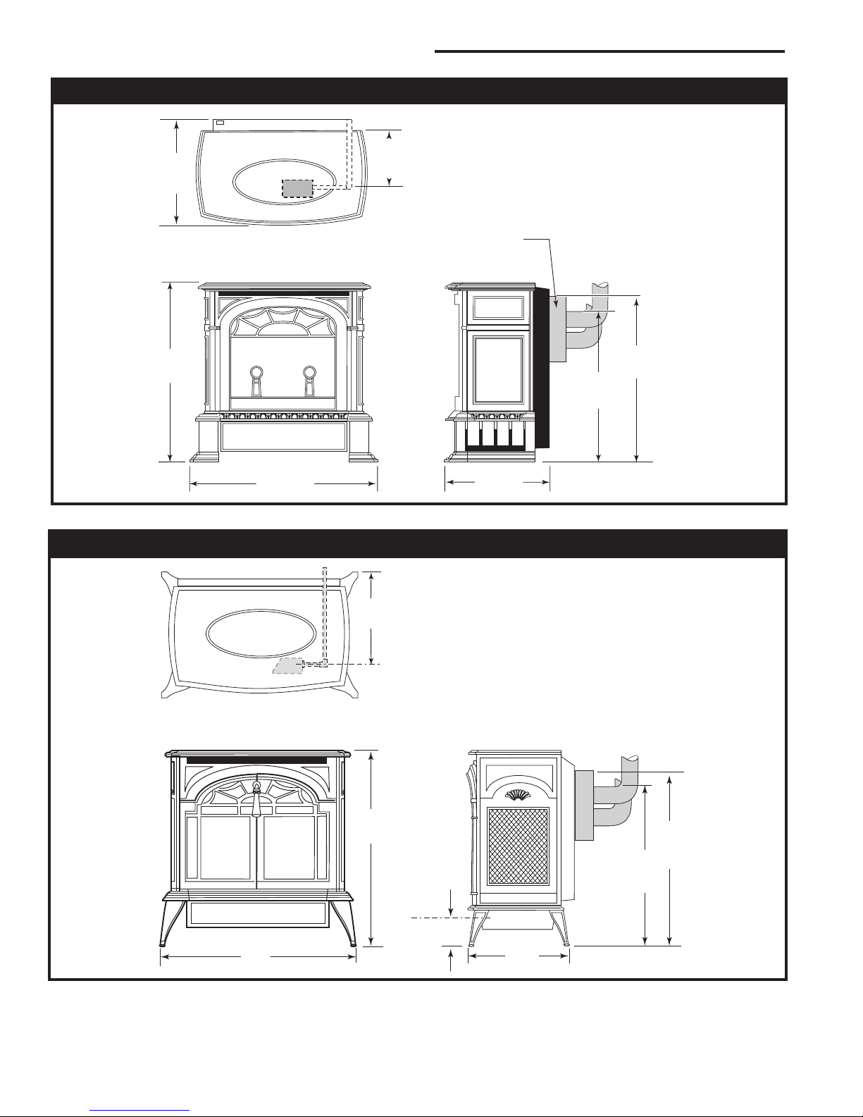
16³⁄₈"
(400mm)
26¹⁄₂"
(673mm)
25¹⁄₄"
(641mm)
22³⁄₈"
(568mm)
24
³⁄₈"
(619mm)
17"
(432mm)
5"
(140mm)
9"
(229 mm)
C
L
Valve
Inlet
26"
(680 mm)
25"
(635 mm)
14"
(356 mm)
3"
(76 mm)
C
L
Valve Inlet
24"
(610 mm)
26"
(660 mm)
Stove Dimensions - Pinnacle Direct Vent Gas Heater
Flue Transition Connector
(For fireplace installation
only)
Fig. 1 PDV20 dimensions.
Stove Dimensions - Stardance Direct Vent Gas Heater
3457
Fig. 2 SDVR dimensions.
4
3457
20007066
Pinnacle & Stardance Direct Vent - Rear Vent Gas Heaters
C
L
"
(476mm)
2"
(64mm)
6"
(150mm)
6"
(150mm)
C
L
18"
(476mm)
2"
(63mm)
2" (50mm)
2"
(50mm)
7¹⁄₂"
(190mm)
Max. Vent
Length
20" (508mm)
Max. Vent
Length
20" (508mm)
7¹⁄₂"
(190mm)
2" (50mm)
2"
(50mm)
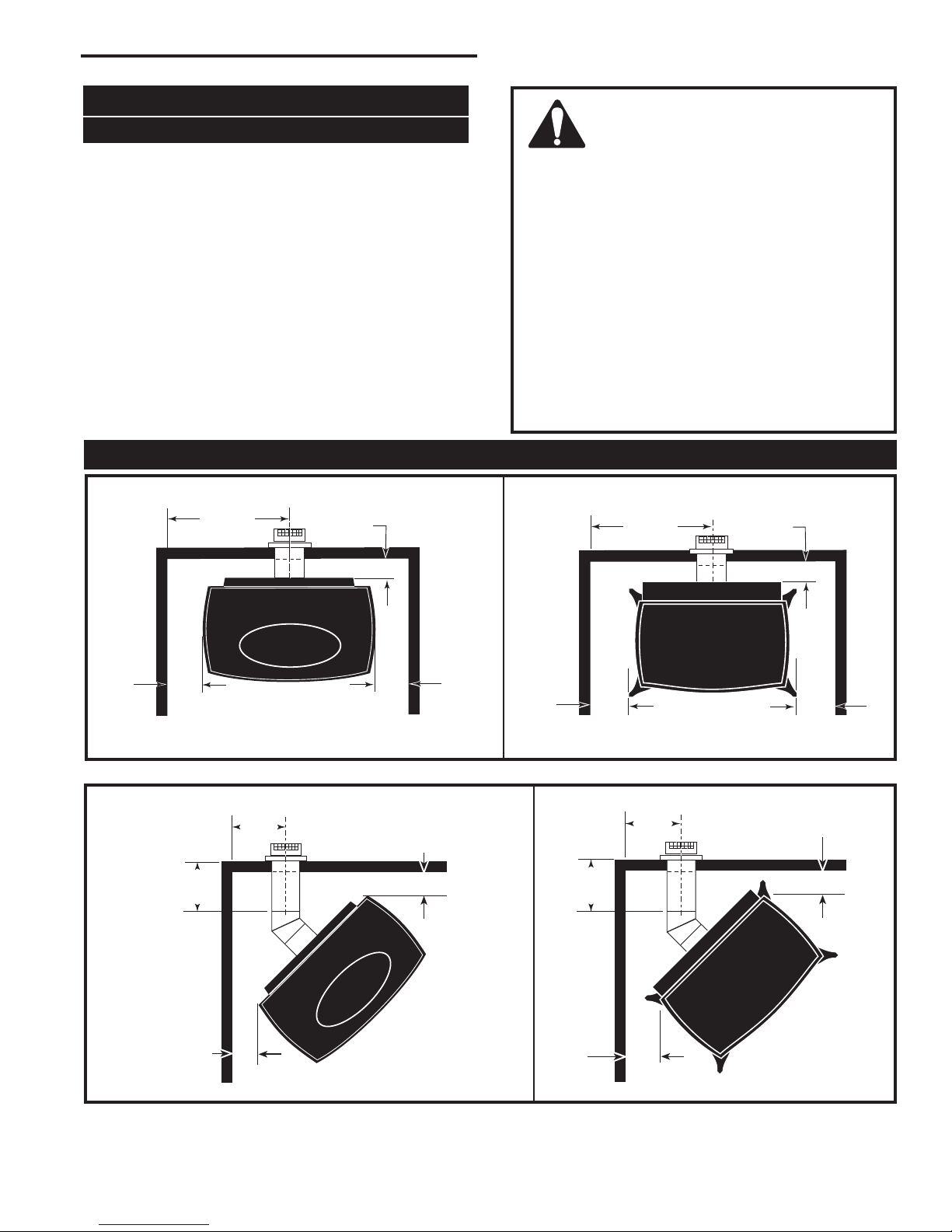
Clearance Requirements
Minimum Clearances to Combustible Materials
Measure side clearances as shown in Figures 3, 4 and
5 from the outer edge of the cast iron stove top. Measure rear clearances from the outermost surface of the
steel rear skirt.
The PDV20 and SDVR heaters are approved for installation into an alcove constructed of combustible materials to the dimensions and clearances shown on the
next page.
The same clearances apply in a standard parallel installation.
Minimum Clearances
Parallel Installation
WARNING:
• Always maintain required clearances
(air spaces) to nearby combustibles
to prevent fire hazard. Do not fill air spaces
with insulation. All venting components must
maintain a 1” (25mm) clearance to combustible materials. Maintain a 6” (152mm) clearance when using single wall pipe. Maintain a
2” (51mm) clearance on top and 1” (25 mm) on
sides and bottom when venting straight off the
rear.
• The gas appliance and vent system must be
vented directly to the outside of the building
and never be attached to a chimney serving a
separate solid fuel or gas-burning appliance.
• Refer to the manufacturer’s instructions included with the venting system for complete
installation procedures.
PDV20
ST128c
Fig. 3 Parallel installation minimum clearances and flue centerline.
Corner Installation
PDV20
Fig. 4 Corner installation minimum clearances.
20007066
SDVR
ST128a
SDVR
ST129a
5
Pinnacle & Stardance Direct Vent - Rear Vent Gas Heaters
9"
(230mm)
Max. Mantel
Width
See
Fig. 6
6"
(150mm)
Sidewall/
Tr
im
2¹⁄₂"
(63mm)
Rear Wall
9"
(230mm)
Max. Mantel
Width
See
Fig. 6
6"
(150mm)
Sidewall/
Tr
im
2¹⁄₂"
(63mm)
Rear Wall
A
B
3" (75mm) Min.
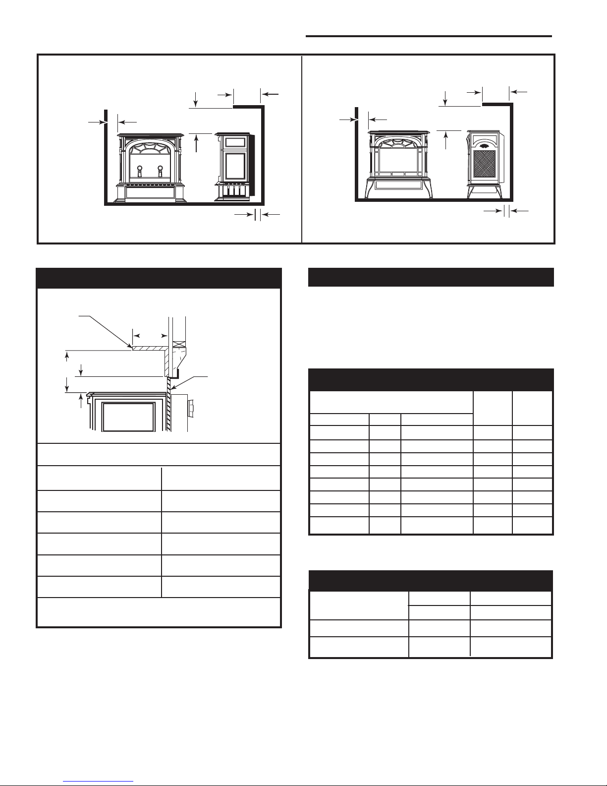
Alcove Installation
ST381
Fig. 5 Alcove installation.
PDV20
Mantel Clearances
Combustible
Mantel or Trim
Materials
Noncombustible
Materials
PDV20 and SDVR
A (Max.) B (Min.)
9” 10
(230 mm) (270 mm)
7
(190 mm) (230 mm)
6” 7
(152 mm) (190 mm)
4
(114 mm) (152 mm)
3” 4
(76 mm) (114 mm)
1¹⁄₂” 3”
(38 mm) (76 mm)
A = Depth of Mantel and/or Top Trim
B = Height from Top of Heater
Fig. 6 Mantel / top trim clearances.
¹⁄₂” 9”
¹⁄₂” 6”
¹⁄₂”
¹⁄₂”
¹⁄₂”
ST382
SDVR
ST381a
Hearth Requirements
The PDV20 and SDVR Heaters must be installed on
rigid flooring. When the heater is installed directly on
any combustible surface other than wood flooring, a
metal or wood panel extending the full width and depth
of the unit must be used as the hearth. There are no
other hearth requirements.
Gas Specifications
Max. Min.
Input Input
Model Fuel Gas Control BTU/h BTU/h
PDV20RN Nat Millivolt 21,000 15,500
PDV20RP Prop Millivolt 21,000 16,500
PDV20RFN Nat Comfort Control 21,000 15,500
PDV20RFP Prop Comfort Control 21,000 16,500
SDVRRN Nat Millivolt 21,000 15,500
SDVRRP Prop Millivolt 21,000 16,500
SDVRRFN Nat Comfort Control 21,000 15,500
SDVRRFP Prop Comfort Control 21,000 16,500
Weight: Fully assembled 350 lbs.
Gas Inlet and Manifold Pressures
Natural LP (Propane)
Inlet Minimum 5.5” w.c. 11.0” w.c.
Inlet Maximum 14.0” w.c. 14.0” w.c.
Manifold Pressure 3.5” w.c. 10” w.c.
6
20007066
Pinnacle & Stardance Direct Vent - Rear Vent Gas Heaters
20
19
18
16
15
14
13
12
11
10
9
8
7
6
5
4
3
2
1
0
1 2 3 4 5 6 7 8 9 10 11 12 13 14 15 16 17 18 19 20
Vertical Run (in feet)
Measured after the first elbow. (Transition elbow)
Horizontal Run (in feet)
21
22
23
24
25
26
27
28
29
30
ST134a
FDV28
Horizontal
vent run
12/3/99 djt
areas modified
1/11/00 djt
Pinnacle / Stardance
Direct Vent / Rear Vent
Certified to:
ANSI Z21.88-2005 / CSA Z2.33-2005
Vented Gas Fireplace Heaters
The installation must conform with local codes or, in
the absence of local codes, with the National Fuel Gas
Code, ANSI Z223.1/NFPA 54 - latest edition. (EXCEPTION: Do not derate this appliance for altitude. Maintain the manifold pressure at 3.5” w.c. for Natural Gas
and 10” w.c. for Propane.)
High Elevations
Input ratings are shown in BTU per hour and are
certified without deration for elevations up to
4,500 feet (1,370m) above sea level.
For elevations above 4,500 feet (1,370m) in USA,
installations must be in accordance with the
current ANSI Z223.1/NFPA 54 and/or local codes
having jurisdiction.
In Canada, please consult provincial and/or local
authorities having jurisdiction for installations at
elevations above 4,500 feet (1,370m).
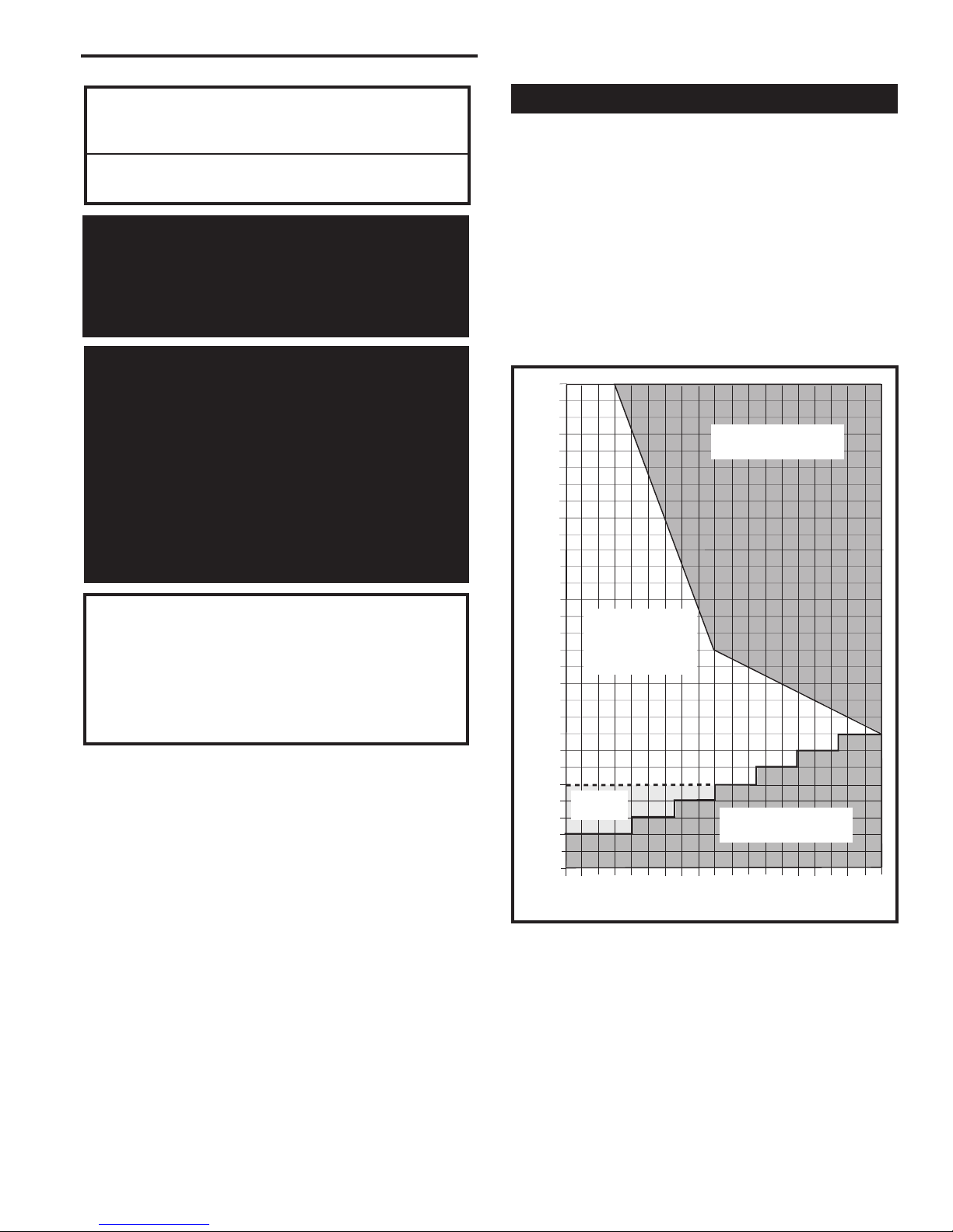
Horizontal Termination
The vent must rise vertically a minimum of 24” (610mm)
after the first elbow directly off the back of the unit,
before the next elbow. The horizontal run may extend
up to 20’ (6m) and include a vertical rise of up to 40’
(12m). (Fig. 7) Horizontal termination must also meet
the criteria shown in Figures 9 and 10.
• Approved vent systems must terminate above and
including the heavy line in Figure 7.
• Two 45° elbows may be substituted for each single
90˚ elbow.
• With a rise between 2’ - 5’, one 90° or two 45° elbows may be used (Excluding the first elbow directly
off the back of the unit.
Unacceptable
Venting Configuration
WARNING: Improper installation, adjustment, alteration, service or maintenance
can cause injury or property damage. Refer
to this manual for correct installation and
operational procedures. For assistance or
additional information consult a qualified
installer, service agency, or the gas supplier.
20007066
May use up to
three 90° Elbows
(Excluding elbow
directly off back
of unit.)
One 90°
Elbow*
Unacceptable
Venting Configuration
Fig. 7 Horizontal vent termination window.
* Not the transition elbow.
ST134f
7
Pinnacle & Stardance Direct Vent - Rear Vent Gas Heaters
20
19
18
16
15
14
13
12
11
10
9
8
7
6
5
4
3
2
1
0
20
1 2 3 4 5 6 7 8 9 10 11 12 13 14 15 16 17 18 19
Vertical Run (in feet)
(Measured after the first elbow. (Transition elbow)
Horizontal Run (in feet)
21
22
23
24
25
26
27
28
29
30
31
32
33
34
35
36
37
38
39
40
ST132f
Pinstar
Ve
rtical
vent run
10/9/00 djt
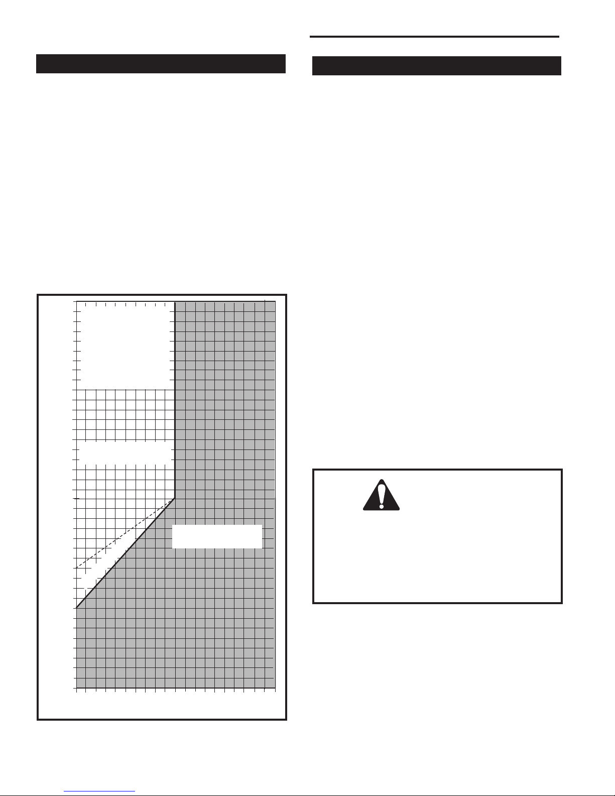
Vertical Termination
A vertical vent system must terminate no less than 8’
(2.44m) and no more than 40’ (12m) above the appliance flue collar. A 2¹⁄₄" restrictor plate (supplied) must
be used (where specified) in all vertically terminated
vent systems. NOTE: The restrictor plate supplied
with the vertical termination should be discarded.
Install restrictor plate supplied with stove directly at
stove outlet. A vertically terminated vent system must
also conform to the following criteria:
• No more than three 90° elbows may be used. 90°
elbow off back must be transition elbow.
• Two 45° elbows may be substituted for one 90°
elbow. No more than six elbows may be used.
• Vent must rise a minimum of 2 feet before offset is
used.
• Termination height must conform to roof clearance
as specified in Figure 9.
All Vertical Terminations in this
area Require
use of the 2¹⁄₄”
Restrictor Plate*
Fig. 8 Vertical vent termination window.
8
Vertical terminations
must be within this area
No Restrictor Plate
Unacceptable
Venting Configuration
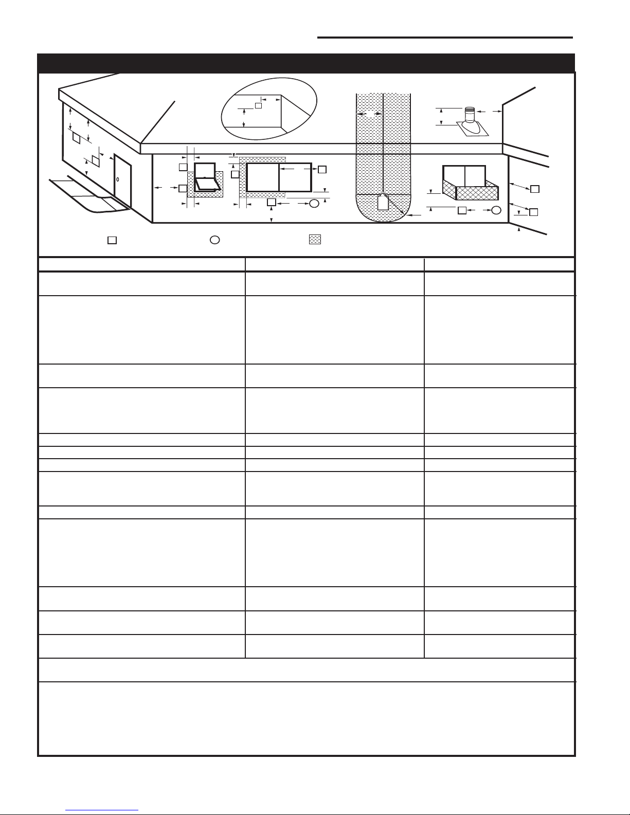
Vent Termination Clearances
When planning the installation, consider the location
of the vent terminal and clearances. Some of the most
common clearances to keep in mind are shown in
Figure 9.
Important: All vent clearances must be maintained.
Check your vent termination clearances against
Figures 9 and 10 .
The vent should be placed so that people cannot be
burned by accidentally touching the vent surfaces when
the stove is operating.
The vent termination should be located where it cannot
be damaged by such things as automobile doors, lawn
mowers or snowblowers and it should be located away
from areas where it could become blocked by snow,
etc.
Some considerations are:
• Obstructions or impediments to venting.
• Nearby combustible materials that could come into
contact with combustion exhaust gases.
• Other nearby openings {within 9” (230mm)} through
which exhaust gas could reenter the building.
• All vegetation within 3’ (914mm) that may interfere
with the draft.
Other factors that influence where the installation will
be sited include the location of outside walls, where
additional heat may be desired in the home, where the
family members gather most regularly, and perhaps
most importantly, the distance limitations of the venting
system.
IMPORTANT
• The horizontal termination must not be recessed
into the exterior wall or siding.
• Horizontal vent runs must be level toward the
vent termination.
• Clearances around the vent termination must be
maintained.
ST132f
20007066

Pinnacle & Stardance Direct Vent - Rear Vent Gas Heaters
Vent Termination Clearances
Your stove is approved to be vented either through the
side wall, or vertical through the roof.
• CFM Corporation does not require any opening
for inspection of vent pipe.
• Only CFM Corporation venting components
specifically approved and labelled for this stove
may be used.
• Minimum clearances between vent pipes and
combustible materials is one (1”) inch (25mm),
except where stated otherwise.
• Venting terminals shall not be recessed into a wall
or siding.
• Horizontal venting must be installed on a level plane
without an inclining or declining slope.
There must not be any obstruction such as bushes, garden sheds, fences, decks or utility buildings within 24”
from the front of the termination hood.
Do not locate termination hood where excessive snow
or ice build up may occur. Be sure to check vent termination area after snow falls, and clear to prevent accidental blockage of venting system. When using snow
blowers, make sure snow is not directed towards vent
termination area.
Location of Vent Termination
It is imperative the vent termination be located observing the minimum clearances as shown in Figure 9.
20007066
9
Pinnacle & Stardance Direct Vent - Rear Vent Gas Heaters
V
V
V
V
V
V
V
X
X
X
D
E
B
B
B
C
B
M
B
A
J
K
F
L
VENT TERMINATION AIR SUPPLY INLET
AREA WHERE TERMINAL IS NOT PERMITTED
H
I
Fixed
Closed
Fixed
Closed
Operabl
e
Operable
Fixed
Closed
V
B
INSIDE
CORNER DETAIL
V
A
G
V
N
N
V
V
G
G
A
CFM145a
General Venting Information - Termination Location
Canadian Installations1 US Installations
A = Clearance above grade, veranda, porch, 12” (30cm) 12” (30cm)
deck, or balcony
B = Clearance to window or door that may be 6” (15cm) for appliances 6” (15cm) for appliances
opened < 10,000Btuh (3kW), 12” (30cm) < 10,000 Btuh (3kW), 9”
for appliances > 10,000 Btuh (3kW) and (23cm) for appliances > 10,000
< 100,000 Btuh (30kW), 36” (91cm) Btuh (3kW) and < 50,000 Btuh
for appliances > 100,000 Btuh (30kW) (15kW), 12” (30cm) for
appliances > 50,000 Btuh (15kW)
C = Clearance to permanently closed window 12” (305mm) recommended to 12” (305mm) recommended to
prevent window condensation prevent window condensation
D = Vertical clearance to ventilated soffit located
above the terminal within a horizontal 18” (458mm) 18” (458mm)
distance of 2’ (610mm) from the center
line of the terminal
E = Clearance to unventilated soffit 12” (305mm) 12” (305mm)
F = Clearance to outside corner see next page see next page
G = Clearance to inside corner (see next page) see next page see next page
H = Clearance to each inside of center line 3’ (91cm) within a height of 15’ (5m) 3’ (91cm) within a height of 15’
extended above meter/regulator assembly above the meter/regulator assembly (5m)above the meter/regulator
assy
I = Clearance to service regulator vent outlet 3’ (91cm) 3’ (91cm)
J = Clearance to nonmechanical air supply inlet 6” (15cm) for appliances < 10,000 6” (15cm) for appliances
to building or the combustion air inlet to any Btuh (3kW), 12” (30cm) for < 10,000 Btuh (3kW), 9”
other appliances appliances > 10,000 Btuh (3kW) and < (23cm) for appliances > 10,000
100,000 Btuh (30kW), 36” (91cm) Btuh (3kW) and < 50,000 Btuh
for appliances > 100,000 Btuh (30kW) (15kW), 12” (30cm) for
appliances > 50,000 Btuh (15kW)
K = Clearance to a mechanical air supply inlet 6’ (1.83m) 3’ (91cm) above if within 10’
(3m) horizontally
L = Clearance above paved sidewalk or paved 7’ (2.13m)† 7’ (2.13m)†
driveway located on public property
M = Clearance under veranda, porch, deck or 12” (30cm)‡ 12” (30cm)‡
balcony
N = Clearance above a roof shall extend a minimum of 24” (610mm) above the highest point when it passes through the roof
surface, and any other obstruction within a horizontal distance of 18” (450mm).
1 In accordance with the current CSA-B149 Installation Codes
2 In accordance with the current ANSI Z223.1/NFPA 54 National Fuel Gas Codes
† A vent shall not terminate directly above a sidewalk or paved driveway which is located between two single family dwellings and serves both
dwellings
‡ only permitted if veranda, porch, deck or balcony is fully open on a minimum 2 sides beneath the floor:
NOTE: 1. Local codes or regulations may require different clearances.
2. The special venting system used on Direct Vent Stoves are certified as part of the appliance, with clearances tested and approved by the
listing agency.
10
Fig. 9 Vent termination clearances.
20007066
2
Pinnacle & Stardance Direct Vent - Rear Vent Gas Heaters
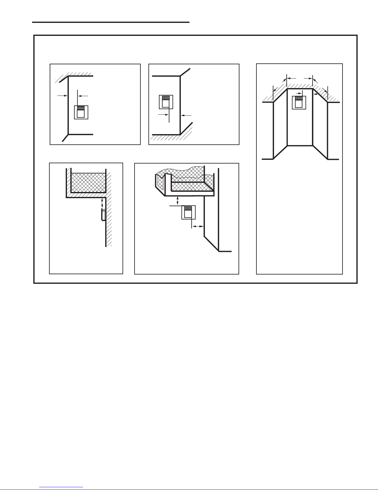
Outside Corner
Inside Corner
Termination Clearances
Termination clearances for buildings with combustible and noncombustible exteriors.
A =
Combustible
6"(152mm)
Noncombustible
2"(50mm)
B =
Combustible
6"(152mm)
Noncombustible
2"(50mm)
A
Balcony -
with no side wall
G =
Combustible &
Noncombustible
12"(305mm)
G
Balcony -
with perpendicular side wall
H = 24"(610mm)
J = 20"(508mm)
H
J
B
Recessed Location
C = Maximum depth of 48"
(1219mm) for recessed
location.
D = Minimum width for back wall
of a recessed location.
Combustible 38"(965mm)
Noncombustible 24"(610mm)
E = Clearance from corner in
recessed location.
Combustible 6"(152mm)
Noncombustible 2"(50mm)
C
D
C
E
V
V
Combustible &
Noncombustible
V
V
V
Fig. 10 Termination clearances.
20007066
584-15
11

Pinnacle & Stardance Direct Vent - Rear Vent Gas Heaters
Vent Components
The following kits are available to meet the needs of most
installations. All pipe has a 7” outer diameter and includes a
4” diameter inner section. A (CG) designation indicates the
part is finished in Charcoal Gray paint. Consult your dealer
about other vent parts that may be appropriate to complete
the installation.
CFM Corporation Vent Components
Rear Vent Kit 7TFSRSK
(1) 20” Starter pipe (CG) for through wall installation
(1) Side Wall Termination
(1) Finishing Collar (CG)
(1) Firestop
(1)Zero Clearance Sleeve
(1) Wall plate (CG)
(1) Hardware Package
Min. Through the Wall Vent Kit 7TFSSK
(1) 90-Degree Elbow (CG)
(1) 24” Straight pipe (CG)
(1) 24” - 42” Adjustable Straight Pipe
(1) Side Wall Termination
(1) Firestop
(1) Zero-clearance sleeve
(1) Hardware package
(1) Finishing plate (CG)
(1) Finishing collar (CG)
(4) Charcoal Gray flue pipe rings
Starter Kit for
Below-Grade Installation 7TFSDVSKS
(1) Snorkel Termination (7TDVSNORK)
Vertical Termination Kit, 1/12-6/12 Pitch
7TDVSKVA
(1) Combination Horizontal Offset / Roof Support
(1) Vertical Termination
(1) Storm Collar
(1) 1/12-6/12 Flashing
(1) Finishing Plate (CG)
(1) Finishing Collar (CG)
(1) Polished Brass Flue Pipe Ring
(1) Hardware Package
Vertical Termination Kit, 7/12-12/12 Pitch
7TDVSKVB
(1) 7/12 - 12/12 Flashing
and all of the other Vertical Termination parts.
Vertical Termination, Flat Roof 7DVSKVF
(1) Flat Flashing
and all of the other Vertical Termination parts.
Twist Lock 12” Straight Pipe (CG) 7TFSDVP12
(1) 12” Non-adjustable Pipe
Twist Lock 12”-18” Straight Pipe (CG)
(1) 12” - 18” Adjustable Pipe
7TFSDVP1218
Twist Lock 24” Straight Pipe (CG) 7TFSDVP24
(1) 24” Non-adjustable Pipe
Twist Lock 48” Straight Pipe (CG) 7TFSDVP48
(1) 48” Nonadjustable Pipe
Twist Lock 45-Degree Elbow (CG) 7TFSDVT45
for vertical offsets
(1) 45-degree Elbow
Combination Offset/Roof Support 7DVCS
Attic Insulation Shield 7DVAIS
7” Charcoal Gray Pipe Rings, (4) 7FSDRG
7” Polished Brass Pipe Rings (4) 7FSDRP
Use the following approved CFM/Majestic vent components for fireplace installations vented through a
masonry chimney:
7TFSCSK Transition Connector
HEDV25 25-foot flex connector
(two 25 foot sections)
HEDV35 35-foot flex connector
(two 35 foot sections)
HEDV32T812 Vent termination for 8 x 12” flue
HEDV32T1212 Vent termination for 12 x 12” flue
HEDVT Round termination
12
20007066

Unpack the Stove
Pinnacle & Stardance Direct Vent - Rear Vent Gas Heaters
Installation
The stove is shipped fully assembled on its back. Unpack the stove and carefully set it upright.
CAUTION
Porcelain enamelled surfaces are fragile. Handle
porcelain enamelled castings tenderly. Familiarize
yourself with the assembly steps before you begin
and proceed with deliberation and care. If possible,
have assistance available.
Place enamelled castings on a soft, cushioned surface until you are ready to assemble.
Avoid contact between the castings and other hard
surfaces or objects.
NOTE: Verify the two relief doors (located on top of
the firebox) are properly seated on the gasket. The
doors sit flush on the gasket, and should lift easily
from the seal around the opening.
If you are not installing a fan, proceed to the appropriate vent assembly section.
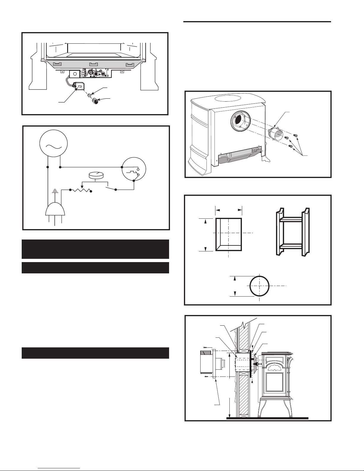
Install Optional Fan Kit #2960/FK28
Fan Kit Contents:
• #10 x 1/2” phillips screws, 6
• Control Knob
• Retainer Collar
• Snapstat • Snapstat Bracket
• Blower Assembly w/ Rheostat Control
NOTE: The Rheostat Assembly and the Snapstat Assembly are not used on RF Models.
For RF Models only: Follow Step 3, then run the
spliced female leads to the front of the stove and attach
to PC board of RF valve. Then follow Step 5.
1. Attach the Snapstat to the Bracket using two #10 x
1/2” phillips sheet metal screws as shown in Figure
12.
2. Locate and remove the 1/4-20 x 3/8” hex head bolt
installed in the hole in the right rear ledge of the
firebox. (Fig. 11) Use that bolt to secure the Snapstat
Bracket to the firebox. The mounting hole is slotted
to allow you to adjust the bracket so that its head
makes contact with the firebox surface. (Fig. 11)
3. Attach the Fan to the firebox by engaging the up
per flange of the fan skirt under the lower edge of
the Shroud and secure the skirt with the four screws
provided with the kit. (Figs. 12, 13)
-
1/4-20 x 3/8”
Hex Head Bolt
Bracket
Snapstat
FK101a
Fig. 11 Snapstat assembly and installation.
Upper
Flange
Fig. 12 The upper flange of the fan skirt should be located
behind the lower edge of the shroud.
Fig. 13 Correct position of fan skirt installation.
1/2” Sheet
Metal Screws
ST240
ST241
4. The rheostat control switch attaches to the left side of
the valve bracket at the front of the stove. (Fig. 14)
• Insert the switch box shaft through the hole in the
back of the right side of the valve bracket, aligning
the locator pin with the smaller hole in that bracket.
• Attach the retaining nut to the switch control shaft
to secure it to the plate.
• Attach the Control Knob to the rheostat shaft.
• Use the wire tie to secure the fan and rheostat
wire harnesses together.
20007066
13
Pinnacle & Stardance Direct Vent - Rear Vent Gas Heaters
27³⁄₈"
(695mm)
to Top of
Opening
9³⁄₈"
(240mm)
10³⁄₈"
(265mm)
7¹⁄₂" Dia.
(190mm)
MOTOR
SNAPSTAT
ON/OFF
RHEOSTAT
WHT
WHT
BLK
BLK
BLK
GRN
BLK
Retaining Nut
centerline. It may be necessary to first position the
stove and measure to find the hole location. Depending on whether the wall is made of combustible
materials, cut the opening to the size shown in Figure 17. Combustible wall openings must be framed
as shown in Figure 17.
3. Measure the wall thickness and cut the wall sleeve
sections to proper length (MAXIMUM 12”). Assemble
Rheostat
Rheostat Knob
FK104
Fig. 14 Attach rheostat to bracket.
Blower Wiring Diagram
Fan Assembly
No. 000-2960 / FK28
WARNING:
DISCONNECT
ELECTRICAL SUPPLY
BEFORE SERVICING
Fig. 15 Blower wiring diagram.
Venting System Assembly -
Direct Vent
General Information
The PDV20 and SDVR are approved for installation
only with the vent components listed on Page 13. Follow the vent component instructions exactly. These instructions apply to both the PDV20 and the SDVR shell.
Sealant
Phillips
Screws
ST396a
Fig. 16 Apply sealant to the starter pipe, and fasten to stove
with Phillips screws.
Vent Opening - Combustible Wall
Framing Detail
Vent Opening -Noncombustible Wall
VO584-100
For U.S. installations: The venting system must conform with local codes and/or the current National Fuel
Gas Code, ANSI Z223.1/NFPA 54
For Canadian installations: The venting system must
conform to the current CSA B149.1 installation code.
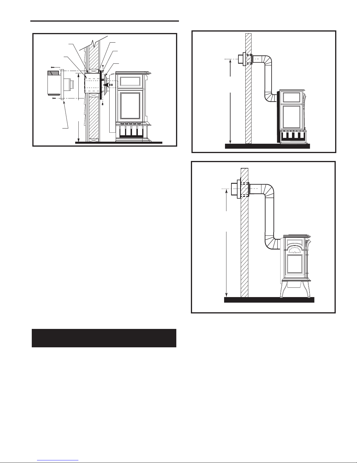
Rear Vent
Use Rear Vent Kit 7TFSRSK for an installation where
the heater is parallel to the wall and the vent system
extends straight back through that wall.
1. Attach Inner Starter Pipe, (found in with the logset),
to the stove.
• Run a bead of sealant beneath the pipe bead and
attach to the stove using three 1/4-20 x 3/8” phillips
screws provided in the parts bag. (Fig. 16)
2. Locate the vent opening on the wall. Refer to Figures 17, 18 & 19 to determine the top of the opening
14
Fig. 17 Locate vent opening.
9³⁄₈” W x 10³⁄₈” H
Wall Opening
Wall Sleeve
- Seal Around
Seal
Around
Terminal
ST400
Firestop
Ventilated Wall Plate
- Open End Down
Finishing Collar
Fig. 18 SDVR with Rear Vent Kit 7TFSRSK installation.
20007066
Pinnacle & Stardance Direct Vent - Rear Vent Gas Heaters
25³⁄₄"
(654mm)
to Top of
Opening
59¹⁄₄"
(1505mm)
61"
(1549mm)
9³⁄₈” W x 10³⁄₈” H
Wall Opening
Wall Sleeve
- Seal Around
Seal
Around
Terminal
ST400
Fig. 19 PDV20 with Rear Vent Kit 7TFSRSK installation.
Firestop
Ventilated Wall Plate
- Open End Down
Finishing Collar
the sleeve with the #8 sheet metal screws supplied.
Attach the firestop plate to the sleeve end with the
holes. (Fig. 25) NOTE: The wall sleeve is required in
combustible walls only.
4. Install the Wall Firestop/Sleeve assembly into the
wall cutout and fasten the firestop to the wall cutout
framing members. (Figs. 18, 19)
5. Measure, and cut if necessary, the appropriate
length of pipe section needed to make the connection through the wall.
6. Slip the wall plate and trim collar over the interior
end of the horizontal pipe and install into the wall
sleeve. Seal the joint inside the wall plate if needed
to keep cold air from being drawn into the home.
7. Connect the pipe to the inner collar. Fasten the wall
plate to the pipe with three sheet metal screws. Slide
the trim collar up against the wall plate to cover the
screws. (Figs. 18, 19)
8. Install the vent terminal. (Figs. 18, 19) Guide the
inner and outer vent termination collars into the adjacent pipes. Double check that the vent pipes overlap
the collars by 2”. Fasten the termination to the wall
with the screws provided, and caulk the joint with
weatherproof sealant.
Through Side Wall /
Vent Termination Below Grade
Refer to Figures 20 & 21 for minimum centerline of wall
opening.
1. Attach Inner Starter Pipe, (found in with the logset),
to the stove.
• Run a bead of sealant beneath the pipe bead and
attach to the stove using three 1/4-20 x 3/8” phillips
screws provided in the parts bag. (Fig. 22)
2. Dry fit the inner and outer pipe of the first elbow
directly to the starter pipe.
20007066
ST131c
Fig. 20 Minimum wall thimble centerline.
ST131b
Fig. 21 Minimum wall thimble centerline.
3. Dry fit the Inner pipe assembly to the stove for the
purpose of determining the center line of the pipe on
the wall.
• Side Wall Terminations: Dry fit the outer elbow
with the vertical outer vent and confirm the centerline
alignment with the wall thimble opening.
4. Attach the elbow to the starter pipe.
• Run a bead of sealant about 1/2” from end of the
starter pipe and attach the assembly to the stove
using three 1/4-20 x 3/8” Phillips screws provided in
the parts bag. (Fig. 22)
15
 Loading...