

Vermont Castings Non-Catalytic Convection Heater 2478CE, DutchWest 2478CE Installation And Operating Manual
Non-Catalytic
Convection
Heater
Model 2478CE
Homeowner’s
Installation and
Operating Manual
For use in Europe
If this heater is not properly installed, operated, and maintained, a house fire may result.
For safety, follow all installation, operation and maintenance directions. Contact local
building officials about restrictions and installation inspection requirements in your
area.
DO NOT DISCARD THIS MANUAL: Retain for future use
SAFETY NOTICE
30003850 8/08 Rev. 2
Dutchwest Non-Catalytic Convection Heater
The Dutchwest Model 2478CE covered in this Owner’s Guide has been tested and listed to current standards.
The test standards utilized were UL 1482 for the United States and EN13240:2001 + A2:2004 for Europe.
Dutchwest Model 2478CE is not listed for mobile home installations.
This heater meets the U.S. Environmental Protection Agency’s
emission limits for wood heaters sold on or after July 1, 1990.
PLEASE NOTE
Read this entire manual before you install and use
your new room heater. Failure to follow instructions
may result in property damage, bodily injury or loss of
life. Save these instructions for future use.
Table of Contents
Specifications ............................................................ 3
Installation ..........................................................4
Assembly ..........................................................11
Operation ..........................................................13
Maintenance .....................................................18
Draft Management ............................................21
Replacement Parts ...........................................24
Warranty ...........................................................
Patents:
U.S.: D288357, 4502395, 4646712
Resolute Acclaim: 4683868,D308246
Canada: 1235969. Other foreign mechanical patents issued.
27
Accessories
• Clearance-reducing Right Side Heat Shields
• Clearance-reducing Heat Shields for single-wall
stove pipe
• Variable-speed Blower
• Outside Air Termination Kit
• Clearance Reducing Rear Exit Flue Heat Shield
• Clearance Reducing Top Exit Flue Heat Shield
2
30003850
G
F
E
D
C
B
A
Dutchwest NC Model 2478CE
Dutchwest Non-Catalytic Convection Heater
Specifications
Nominal heat output ............. 11.6 kW (39,600 BTU/hr)
Minimum flue draught ...................... 12 Pa (0.048” WG)
Mean flue gas temp .............................. 457° C (855° F)
Efficiency (space heating) ...................................72.0%
Area heated .................74-149 sq. m (800-1600 sq. ft.)
Fuel size/type .................................560 mm (22”) wood
Flue mass gas flow .............................................7.7 g/s
CO Emissions (@ 13% O2) ............................. 900 ppm
Loading ....................................................Side and front
Chimney connector .....................152 mm (6”) diameter
Chimney flue size ........................152 mm (6”) diameter
Flue exit position ..........................................Top or rear
Air control ................................................................One
Ash handling system ..................... Removable ash pan
Glass panels .........................High temperature ceramic
1
Weight .................................................
191 kg (420 lbs.)
Width (leg-to-leg) ...................................695 mm (27¹⁄₄”)
Depth (leg-to-leg) ..................................445 mm (17¹⁄₂”)
Height to top of flue collar ......................775 mm (30¹⁄₂”)
1
1. This value can vary depending on how the stove
is operated, the type and moisture content of the fuel
used, as well as the design, construction and climatic
location of your home. Figures shown are based on
nominal fuel consumption obtained under laboratory
conditions and on average efficiencies.
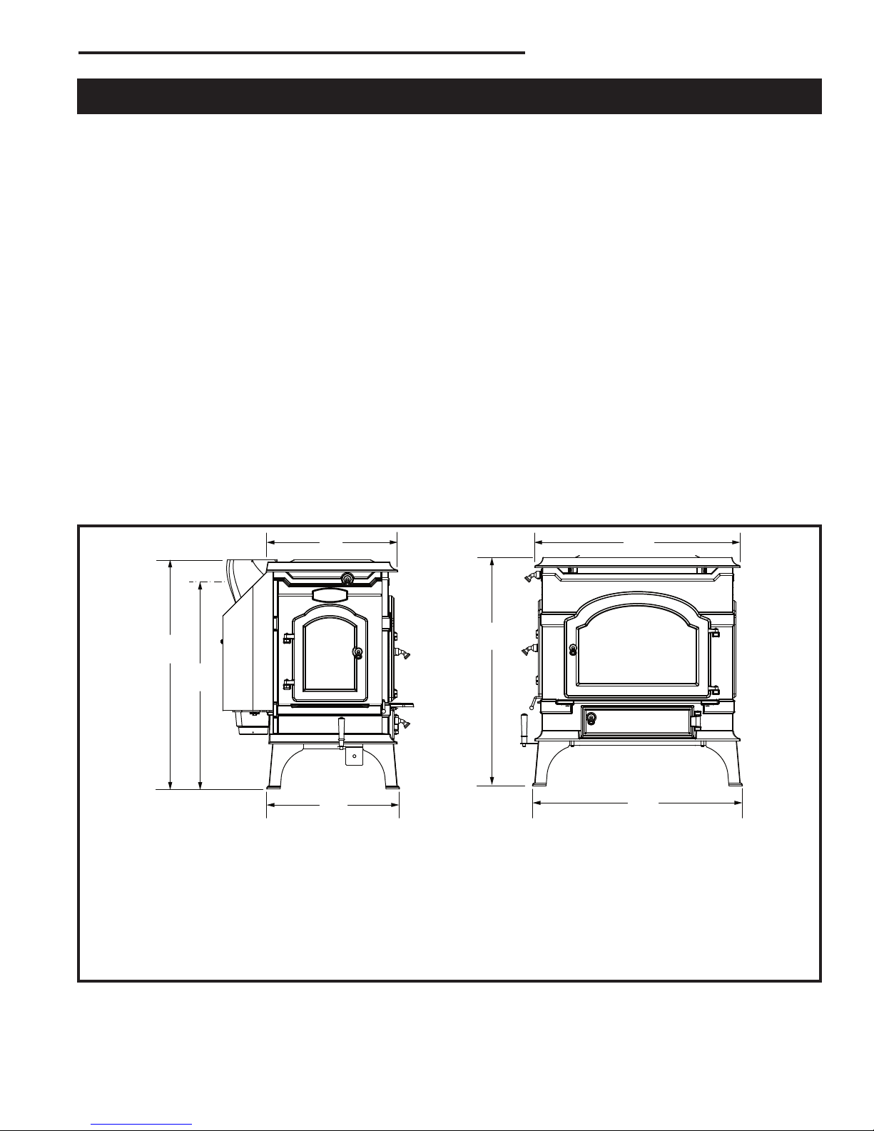
Model 2478CE
A 683 mm (26
B 695 mm (27¹⁄₄”)
C 756 mm (29³⁄₄”)
D 438 mm (17¹⁄₄”)
E 445 mm (17¹⁄₂”)
F 692 mm (27¹⁄₄”) Center of Flue Collar, Rear Exit
G 775 mm (30¹⁄₂”)
Fig. 1 Dutchwest Convection Heater specifications.
30003850
³⁄₄”)
3

Dutchwest Non-Catalytic Convection Heater
Installation
SAFETY NOTICE: IF YOUR DUTCHWEST CONVECTION HEATER IS NOT PROPERLY INSTALLED,
OPERATED AND MAINTAINED, A HOUSE FIRE MAY
RESULT. FOR SAFETY, FOLLOW ALL INSTALLATION, OPERATION AND MAINTENANCE DIRECTIONS. CONTACT LOCAL BUILDING OFFICIALS
ABOUT RESTRICTIONS AND INSTALLATION
INSPECTION REQUIREMENTS IN YOUR AREA.
Before you begin the installation, review your plans to
confirm that:
• Your stove and chimney connector will be far enough
from combustible material to meet all clearance
requirements.
• The floor protector is large enough and is construct
ed properly to meet all requirements.
• You have obtained all necessary permits from local
authorities.
Your local building official is the final authority for ap
proving your installation as safe and for determining
that it meets local and state codes.
The metal label permanently attached to the back of
every Dutchwest stove indicates the stove has been
tested to current standards. The test standard is
EN13240:2001 + A2:2004 for Europe. Clearance and
installation information is printed on the metal label attached to the rear of the stove. Local authorities generally will accept the label as evidence that, when the
stove is installed according to the information on the
label and in this manual, the installation meets codes
and can be approved.
Codes vary in different areas, however. Before starting
the installation, review your plans with the local building
authority. Your local dealer can provide any additional
information needed.
IMPORTANT: FAILURE TO FOLLOW THESE IN
STALLATION INSTRUCTIONS MAY RESULT IN A
DANGEROUS SITUATION, INCLUDING A CHIMNEY
OR HOUSE FIRE. FOLLOW ALL INSTRUCTIONS
EXACTLY, AND DO NOT ALLOW MAKESHIFT COMPROMISES TO ENDANGER PROPERTY AND PERSONAL SAFETY.
-
-
-
Chimney Types
Your Dutchwest Convection Heater must be connected
to a code-approved masonry chimney with a flue liner,
to a relined masonry chimney that meets local codes, or
to a prefabricated metal chimney.
Whatever kind you use, the chimney and chimney connector must be in good condition and kept clean.
Masonry Chimneys
If you use an existing masonry chimney, it must be
inspected to ensure safe condition before the stove
is installed. Your local professional chimney sweep,
building inspector, or fire department official will be able
either to make the inspection or to direct you to someone who can.
An inspection of the chimney must confirm that it has
a lining. Do not use an unlined chimney. The chimney
should also be examined for cracks, loose mortar, other
signs of deterioration, and blockage. Repair any defects
before the chimney is used with your stove.
Unused openings in an existing masonry chimney must
be sealed with masonry to the thickness of the chimney
wall, and the chimney liner should be repaired. Openings sealed with pie plates or wallpaper are a hazard
and should be sealed with mortar or refractory cement.
In the event of a chimney fire, flames and smoke may
be forced out of these unused thimbles.
The chimney should be thoroughly cleaned before use.
A newly-built masonry chimney must conform to the
standards of your local building code or, in the absence
of a local code, to a recognized national code. Masonry
chimneys must be lined, either with code-approved masonry or pre-cast refractory tiles, stainless steel pipe, or
a code-approved, “poured-in-place” liner. The chimney’s
clean-out door must seal tightly.
The flue and chimney design must meet requirement
J2, Part J of the building regulations 2000 (Combustion
Appliances and Fuel Storage Systems).
All local regulations, including those referring to
national and European standards need to be complied with when installing this stove.
4
30003850
Dutchwest Non-Catalytic Convection Heater
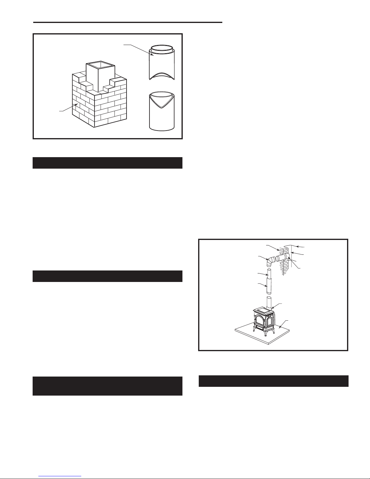
Prefabricated Double-Wall
Insulated Chimney
Tile Lined
Masonry
Chimney
ST241
Fig. 2 If in sound condition and approved for use, either a
masonry or a prefabricated chimney may be used.
Prefabricated Chimneys
These should be an internal diameter of 150 mm (6”)
and be of the twin wall insulated construction that has
been approved for solid fuel use (e.g. Rite Vent ICS of
ICID Lite Chimney Systems). Diameters over 200 mm
(8”) are not recommended due to the large cross-section causing excessive cooling of the flue gases.
A horizontal connector run should be inclined 20 mm
per meter (1/4” per foot) from the stove toward the
chimney. The recommended maximum length of a
horizontal run is 914 mm (36”) and the total length of
chimney connector should be no longer than 2.4 m (8’).
DO NOT CONNECT THIS UNIT TO A CHIMNEY FLUE
SERVING ANOTHER APPLIANCE.
Chimney Size
The Model 2478CE heater should be vented into a masonry chimney with a square flue with nominal flue size
of 203 x 203 mm (8” x 8”), or a round flue with nominal
flue size of 152 mm (6”).
Chimney liners larger than 203 x 305 mm (8” x 12”) may
promote rapid cooling of smoke and reduction in draft,
especially if they are located outside the home. These
large chimneys may need to be insulated or have their
flues relined for proper stove performance.
Accessories to help make the connection between
stainless steel chimney liners and the stove are available through your local dealer.
Guidelines for Installing
the Chimney Connector
The chimney connector is the single-wall pipe, or listed
and approved double-wall pipe that connects the stove
to the chimney. The chimney itself is a masonry or
prefabricated structure that encloses the flue. Chimney
connectors are used only to make the connection from
the stove to the chimney.
Connecting Flue Pipes
Connector pipes should meet the requirements of the
building regulations. This can be achieved by the use
connecting fluepipes included in the following categories:
a) Vitreous enamelled steel pipe complying with BS
6999: 1989 (1996);
b) Pipes made from stainless steel as descirbed in BS
EN 1008-1:1995 grades 1.4401, 1.4404, 1.4432 or
1.4436 with flue wall thickness of at least 1 mm;
c) Mild steel fluepipes complying with BS 1449: Part 1:
1991, with a flue wall thickness of at least 3 mm;
d) Cast iron fluepipes complying with BS 41: 1973
(1998).
Flue Pipes with a spigot and socket joint should be
fitted with the socket facing upwards, to contain condensates and moisture within the flue. Joints should be
made gas tight using proprietary jointing accessories,
or, where appropriate, by packing joint with noncombustible rope and fire cement.
Do not pass the chimney connector through a combustible wall, floor, or ceiling, through an attic or roof space,
or through a closet or similar concealed space. If passage through a combustible wall is unavoidable, follow
the recommendations in the following section on Wall
Pass-Throughs. Keep the passage as short and direct
as possible, with no more than two 90° turns.
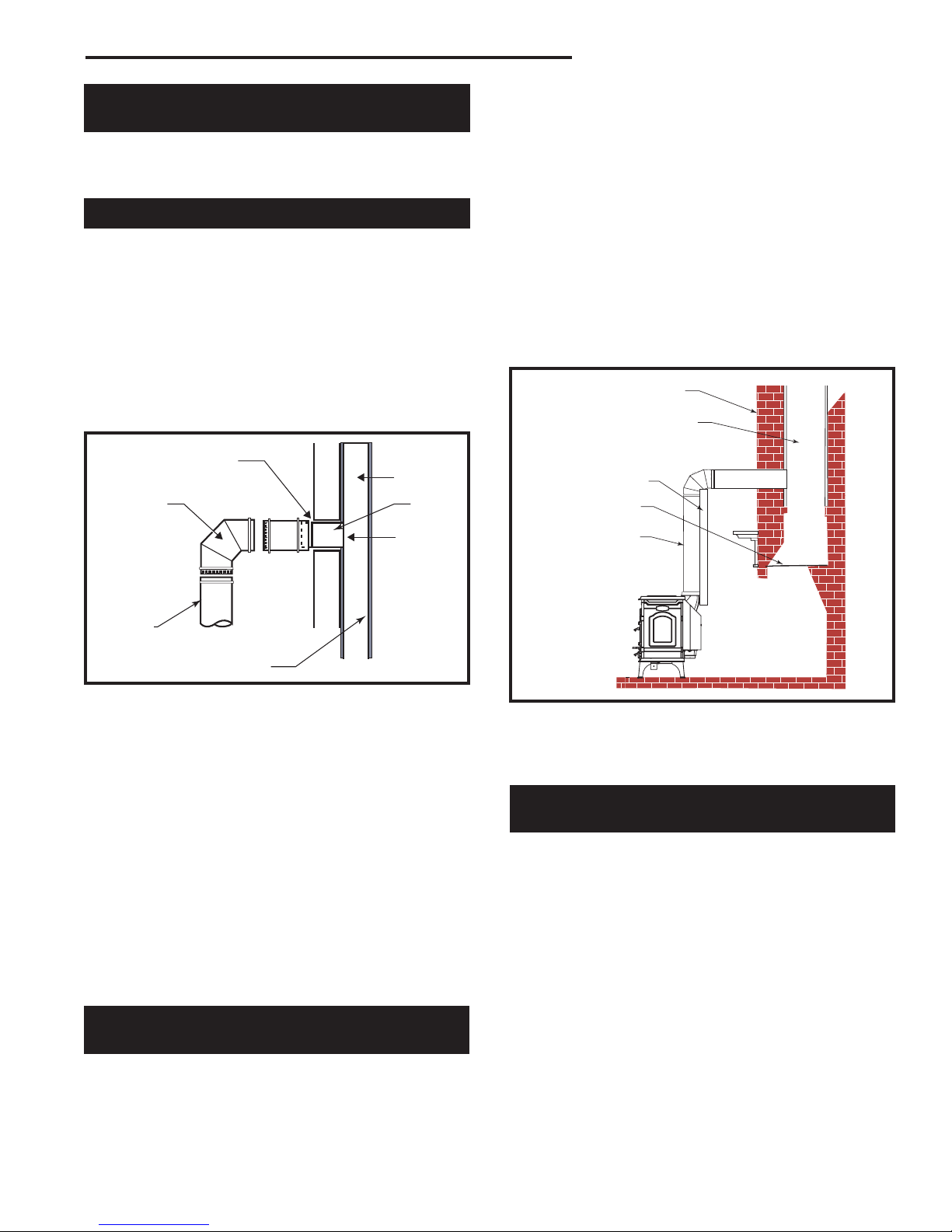
Chimney
Elbow
Slip Pipe
Standard Connector
Flue Collar
Fig. 3 Sections of a steel chimney connector of at least 24
gauge thickness are fastened together with screws to
connect the stove to the chimney.
Flue Liner
Flue
Thimble
Floor Protector
ST418
Two Types of Connector
You may use either a single-wall steel connector of the
size and gauge described below, or a listed and approved double-wall connector.
30003850
5

Dutchwest Non-Catalytic Convection Heater
Single-Wall Connector
The single-wall chimney connector should be made of
24 gauge or heavier steel, and must have a minimum
internal diameter of 152 mm (6”) for model 2478CE.
Install single-wall chimney connector not less than 18”
(450 mm) from the ceiling.
In cathedral ceiling installations, extend the prefabricated chimney downward to within 2.4 m (8’) of the stove.
The entire chimney connector should be exposed and
accessible for inspection and cleaning.
Do not use galvanized chimney connector; it cannot
withstand the high temperatures that can be reached
by smoke and exhaust gases and it may release toxic
fumes under high heat.
Double-Wall Connector
Information on assembling and installing double-wall
connectors is provided by the manufacturer of the
double-wall pipe. Follow the manufacturer’s installation
instructions exactly. Most manufacturers of prefabricated double-wall insulated chimneys also offer doublewall connector pipes. Using a chimney and connector
pipe from the same manufacturer helps simplify the
assembly and installation.
NOTE: For installations using double-wall connectors, minimum clearances must conform to listed
clearances in the Stove and Chimney Connector
Clearance Charts on Page 12 and 13 of this manual.
Assembling Single-Wall
Chimney Connector
SAFETY NOTE: Always wear gloves and safety
goggles when drilling, cutting or joining sections of
chimney connector.
For double-wall
connectors, follow
the manufacturer’s
instructions exactly. For single-wall
connectors, follow
the instructions
below.
1. Insert the
crimped end of the
first section into
the stove’s flue
collar, and keep
each crimped end
pointing toward
the stove (Fig. 4).
Using the holes in
the flue collar as
guides, drill 1/8” (3
Toward
Stove
Flue Gas
Direction
ST242
Fig. 4 Crimped sections always point
toward the stove so that any liquid
condensation will not leak out.
mm) holes in the bottom of the first section of chimney
connector and secure it to the flue collar with three #10
x 1/2” sheet metal screws.
2. Secure each joint between sections of chimney connector, including telescoping joints, with at least three
sheet metal screws.
3. Secure the chimney connector to the chimney. Instructions for various installations follow below.
4. Confirm that the installed stove and chimney con-
nector are correct distances from nearby combustible
material.
NOTE: Special slip pipes and thimble sleeves that form
telescoping joints between sections of chimney connector are available to simplify installations. They can
eliminate the need to cut individual connector sections.
Consult your local dealer about these special pieces.
Securing the Connector to a
Prefabricated Chimney
Follow the installation instructions of the chimney
manufacturer exactly as you install the chimney. The
manufacturer of the chimney will supply the accessories to support the chimney, either from the roof of
the house, at the ceiling of the room where the stove is
installed, or from an exterior wall.
Special adaptors are available from your local dealer
to make the connection between the prefabricated
chimney and the chimney connector. (Fig. 5) The top
of such adaptors attach directly to the chimney or to the
chimney’s ceiling support package, while the bottom of
the adaptor is screwed to the chimney connector.
These adaptors are designed so the top end will fit
outside the inner wall of the chimney, and the bottom
end will fit inside the first section of chimney connector.
Any soot or creosote falling from the inner walls of the
chimney will stay inside the chimney connector.
Prefab (Insulated)
Chimney
Ceiling Support
Package
Prefab Chimney
Adapter
Chimney Connector
(Stovepipe)
ST419
Fig. 5 Joining the chimney connector to a prefabricated
chimney.
6
30003850
Dutchwest Non-Catalytic Convection Heater
Securing the Connector
to a Masonry Chimney
The Dutchwest Convection heater may be connected
to either a freestanding masonry chimney or a masonry
fireplace chimney.
Freestanding Installations
If the chimney connector must pass through a combustible wall to reach the chimney, follow the recommendations in the wall pass-through section that follows.
The opening through the chimney wall to the flue
(the “breech”) must be lined with either a ceramic or
metal cylinder, called the “thimble”, which is securely
cemented in place. (Fig. 6) Most chimney breeches
incorporate thimbles, but check to be sure the fit is snug
and the joint between thimble and chimney wall firmly
cemented.
Thimble
Sleeve
Flue
Elbow
Thimble
Keep
Sleeve
End Flush
with Flue
Tile
connector enters the chimney. Follow all the guidelines
for installing a chimney connector into a freestanding
masonry chimney, and pay special attention to these
additional points:
• Check the stove and chimney connector clearances
to combustible mantel or trim materials. Use the
necessary combination of mantel, trim, and connector heat shields to provide the required clearances.
(Fig. 7)
• Double-check connector clearance from the ceiling.
• The fireplace damper must be closed and sealed
to prevent room air from being drawn up the flue,
reducing the draft. However, it must be possible to
re-open the damper to inspect or clean the chimney.
Masonry Wall
Ceramic Flue Liner
Chimney Connector Shield
Block-Off Plate
Chimney Connector
Chimney
Connector
Flue Liner
Fig. 6 The thimble, made of either ceramic or metal, must be
cemented in place securely.
ST243
A special piece called the “thimble sleeve,” slightly
smaller in diameter than the standard connector and
most thimbles, will ease the removal of the chimney
connector system for inspection and cleaning. Thimble
sleeves should be available from your local dealer.
To install a thimble sleeve, slide it into the breech until
it is flush with the inner flue wall. Don’t extend it into
the actual flue passage, as that could interfere with the
draft.
The thimble sleeve should protrude 25-51 mm (1-2”)
into the room. Use furnace cement and thin gasketing
to seal the sleeve in place in the thimble. Secure the
chimney connector to the outer end of the sleeve with
sheet metal screws.
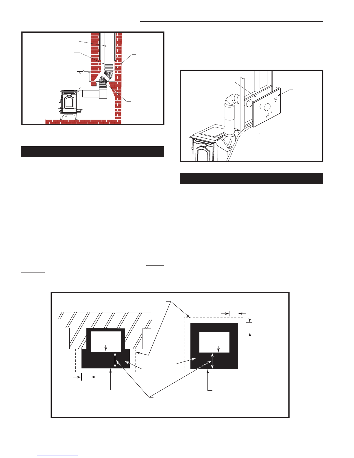
Fireplace Installations -
Above the Fireplace
In this installation, the chimney connector rises from
the stove, turns ninety degrees, and goes back into the
fireplace chimney. The liner of the fireplace chimney
should extend at least to the point at which the chimney
ST796as
Fig. 7 The connector enters flue above the fireplace. If the
clearance between the chimney connector and either the
mantel and/or the ceiling is inadequate, special protective
shields will be required.
Fireplace Installations -
Through the Fireplace
The Convection heater may be installed either without
legs* as a fireplace insert, or with standard legs attached - depending on the safety regulations that apply
to your situation, the height of the fireplace opening and
your own preference. For either situation, the chimney
connector/positive connection kit extends back from the
stove, enters the fireplace cavity, and turns upward. It
then passes through the fireplace damper opening and
smoke chamber and connects to the chimney flue.
In such installations, a “positive connection” must be
made to the chimney flue with a special kit available
from your local dealer. Also, special clearance and floor
protection provisions must be observed. These provisions are discussed in the Clearance and Floor Protection sections respectively.
30003850
7
Dutchwest Non-Catalytic Convection Heater
Flue Liner
Extend Chimney Connector to the First Tile of
the Flue Liner
Observe
Miniumum Clearances
ST797
Damper
Plate is
Removed
or Locked
in Open
Position
Close Off
the Damper
Opening with
Sheet Metal
and Sealant
Fig. 8 The connector passes through the fireplace to enter
flue. Special Fireplace Adapter Kits to simplify fireplace instal
lations are available from your local dealer.
Wall Pass-Throughs
Whenever possible, design your installation so the connector does not pass through a combustible wall. If you
must use a wall pass-through in your installation, check
with your building inspector before you begin and construct it in accordance with local building codes. Also
check with the chimney connector manufacturer for any
specific requirements.
Accessories are available for use as wall passthroughs. If using one of these, make sure it has been
tested and listed for use as a wall pass-through. Figure
9 shows one method of passing a connector through
a wall. All combustible material in the wall is cut away
to provide the required 460 mm (18”) clearance for the
connector. The resulting space must remain empty.
A flush-mounted sheet metal cover may be used
side only. If covers must be used on both sides, each
cover must be mounted on non-combustible spacers at
least 25 mm (1”) clear of the wall. Your Dutchwest deal-
on one
er or your local building inspector can provide details of
other approved methods of passing a chimney connector through a combustible wall.
DO NOT CONNECT THE HEATER TO ANY AIR DIS
-
TRIBUTION DUCT OR SYSTEM.
460 mm (18”) Empty
Space All Around the
Chimney Connector
Sheet Metal
Cover
(One side
only)
-
ST421
Fig. 9 Hollow wall pass-through.
Hearths
This appliance must be installed on to hearth that
meets the requirements of Part J of the Building Regulations 2000 (Combustion Appliances and Fuel Storage
Systems). This can be achieved by ensuring that the
hearth is constructed and sized in accordance with the
guidelines included in section 2 of approved document
‘J’. The size and clearances of the hearth are as follows:
The constructed hearth should be constructed in accordance with the recommendations in document J,
and should be of minimum width 840 mm and minimum
depth 840 mm (if a free standing hearth b) above) or
a minimum projection of 150 mm from the jamb (if a
recessed hearth a) above).
Appliance
Doors
At least
150 mm
Perimeter should be
clearly marked e.g.
edge of superimposed
hearth
a) Fireplace recess b) Free standing
Fig. 10 Noncombustible hearth surface dimensions.
8
Costructional Hearth
Dimensions as below
Hearth Surface
Free of Combustible Material
At least
300 mm
At least 150 mm
or to a suitable
heat resistant wall
Appliance
Doors
Perimeter should be
clearly marked e.g.
edge of superimposed
hearth
ST912
30003850
Dutchwest Non-Catalytic Convection Heater
A
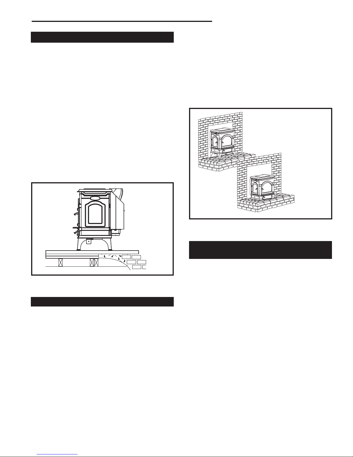
Fireplace Installations
The Dutchwest Model 2478CE has a reversible flue collar to allow for either top exit or rear exit installations.
You may install your Dutchwest Model 2478CE in an
existing fireplace as a fireplace insert with no legs, or
with the standard legs attached.
To install the heater without legs as a fireplace insert,
the floor must be completely noncombustible, such as
an unpainted concrete floor over earth.
Many fireplaces do not satisfy the “completely non
combustible” requirement because the brick or concrete hearth in front of the fireplace opening usually is
supported by heavy wooden framing as in Figure 11.
Because heat passes readily through brick or concrete,
it can easily pass through to the wood. As a result, such
fireplace hearths are considered a combustible floor.
You may not install a heater on a combustible hearth
without legs. Standard leg installations must include the
bottom heat shield. The floor protector must also meet
standard requirements for freestanding installations.
-
Hearth rugs do not satisfy the requirements for floor
protection.
Fireplace insert installations also have specific clear
ance requirements to the side walls, side decorative
trim, and fireplace mantel. This information is found in
“Fireplace Installation Clearances” in this section.
-
REMINDER- FIREPLACE INSERT INSTALLATIONS
WITHOUT LEGS ARE PERMISSIBLE ONLY IF THE
HEARTH IS COMPLETELY NONCOMBUSTIBLE,
SUCH AS UNPAINTED CONCRETE OVER EARTH.
ST799
Fig. 11 Combustible supporting timbers (A) may lie beneath
fireplace hearths; such situations require additional floor
protection.
Floor Protection for Fireplace Installations
Fireplace installations with the standard legs and the
bottom heat shield must have a floor protector of the
same construction as that specified for freestanding
installations. The floor protector must extend at least
406 mm (16”) from the front of the stove and from the
left (loading door) side, and at least 203 mm (8”) from
the right side and rear. It must also provide protection
beneath any horizontal runs of the chimney connector,
including 51 mm (2”) to either side.
Many raised hearths will extend less than the required
distance from the front of the heater when it is installed.
In such cases, sufficient floor protection, as described
above, must be added to extend the hearth 406 mm
(16”).
ST809
Fig. 12 Extra floor protection may be required for the fireplace hearth, even if your stove is installed with the legs and
the bottom heat shield.
Keep the Stove a Safe Distance
From Surrounding Materials
Both a stove and its chimney connector radiate heat in
all directions when operating. A safe installation requires that adequate clearance be maintained between
the stove and nearby combustible materials to ensure
that such materials do not overheat.
Clearance is the distance between either your stove or
chimney connector, and nearby walls, floors, the ceiling,
and any other fixed combustible surface. Keep furnishings and other combustible materials away from the
stove as well. In general, a distance of 1220 mm (48”)
must be maintained between the stove and moveable
combustible items such as drying clothes, furniture,
newspapers, firewood, etc. Keeping those clearance
areas empty assures that nearby surfaces and objects
will not overheat.
30003850
9
 Loading...