

Vermont Castings MLDV500NSCSB, MLDV500PSCSB Installation & Operating Instructions Manual

MLDV Direct Vent Gas Fireplace
Installation & Operating Instructions
Model: MLDV500NSCSB, MLDV500PSCSB
WARNING:
FIRE OR EXPLOSION HAZARD
Failure to follow safety warnings exactly
could result in serious injury, death or
property damage.
• Do not store or use gasoline or other
fl ammable vapors and liquids in the
vicinity of this or any other appliance.
• WHAT TO DO IF YOU SMELL GAS
– Do not try to light any appliance.
– Do not touch any electrical switch; do
not use any phone in your building.
– Leave the building immediately.
– Immediately call your gas supplier from
a neighbor's phone. Follow the gas
supplier's instructions.
– If you cannot reach your gas supplier,
call the fi re department.
• Installation and service must be performed
by a qualifi ed installer, service agency or
the gas supplier.
WARNING: Improper installation, adjustment,
alteration, service or maintenance can cause
injury or property damage. Refer to this manual.
For assistance or additional information consult
a qualified installer, service agency or the
gas supplier.
This appliance may be installed in an aftermarket,*
permanently located, manufactured home (USA
only) or mobile home, where not prohibited by
local codes. This appliance is for use only with
the type of gas indicated on the rating plate. This
appliance is not convertible for use with other
gases, unless a certifi ed kit is used.
* Aftermarket: Completion of sale, not for purpose of resale, from
the manufacturer.
A barrier designed to reduce the risk of burns from the hot
viewing glass is provided with this appliance and shall
be installed for the protection of children and
INSTALLER: Leave this manual with the appliance.
CONSUMER: Retain this manual for future
DANGER
other at risk individuals.
CERTIFIED
SAFETY BARRIER
HOT GLASS WILL
CAUSE BURNS.
DO NOT TOUCH GLASS
UNTIL COOLED.
NEVER ALLOW CHILDREN
TO TOUCH GLASS.
20306543
reference.
20306748 12/14 Rev. 1

MLDV Series Gas Fireplace
CONTENTS
Thank you and congratulations on your purchase of a
Vermont Castings Group Fireplace.
PLEASE READ THE INSTALLATION AND OPERATION INSTRUCTIONS BEFORE USING THE APPLIANCE!
IMPORTANT: Read all instructions and warnings carefully before starting installation.
Failure to follow these instructions may result in a possible fi re hazard and will void the warranty.
Important Safety Information ...............................................3
Code Approval ....................................................................... 4
Product Features ................................................................... 5
Product Specifi cations ...................................................... 5
High Elevations ................................................................ 5
Gas Pressures.................................................................. 5
Gas Specifi cations & Orifi ce Size ..................................... 5
Fireplace & Framing Dimensions ........................................ 6
Pre-Installation Information .................................................. 7
Before You Start ...............................................................7
Items Required for Installation.......................................... 7
Firebox Framing ............................................................... 7
Fireplace Location ............................................................ 7
Clearances ............................................................................. 8
Clearances to Combustibles ............................................8
Secure Fireplace to Floor or Framing.................................. 9
Finishing Material .............................................................9
Venting Installation .............................................................. 10
Installation Precautions ..................................................10
Optional Top Vent Application ......................................... 10
Installation Planning ....................................................... 12
For Horizontal Termination ............................................. 12
For Vertical Termination .................................................. 12
Installing a Vent System in an Outside Chase ...............12
Termination Location ...................................................... 13
Termination Clearances.................................................. 14
How to Use the Vent Graph............................................ 14
Rear Wall Vent Installation ............................................. 15
Horizontal w/Vertical Rise Termination Confi gurations. .. 16
Vertical Side Wall Applications ....................................... 18
Below Grade Installations............................................... 19
Vertical Through-the-Roof Applications .......................... 20
Installation for Vertical Termination ................................. 21
Flat Ceiling Installation ...................................................21
Flex Vent Installation ...................................................... 23
4 x 7 Flex Pipe................................................................ 25
Fireplace Installation ........................................................... 26
Check Gas Type ............................................................. 26
Installing Gas Piping to Fireplace Location .................... 26
Installing Items Needed .................................................. 26
Check Gas Pressure — Millivolt .................................... 27
Electrical Installation — Millivolt........................................ 28
Electrical Wiring .............................................................. 28
Remote Wall Mounted Switch ........................................ 28
Optional Fan/Blower (BLOTBLDV)................................. 28
Operating Instructions — Millivolt ..................................... 31
For Your Safety............................................................... 31
Lighting Pilot for the First Time ....................................... 31
Lighting Pilot ................................................................... 32
Lighting Burner ............................................................... 33
Check Gas Pressure ...................................................... 34
Electrical Installation — Signature Command ................. 34
Electrical Wiring .............................................................. 34
Junction Box Wiring........................................................ 35
Command Center Wall Installation ................................. 35
Wall Switch Installation ................................................... 35
Signature Command Wiring Diagram............................. 36
Optional Fan/Blower System — Signature Command ..... 37
BLOTSDVSC.................................................................. 37
BLOTSDV....................................................................... 38
Operating Instructions — Signature Command ............... 39
For Your Safety............................................................... 39
Operating Instructions ....................................................40
To Turn Off Gas To Appliance ......................................... 40
Signature Command System Operation.............................41
Features ..........................................................................41
Battery Installation ...........................................................41
System Confi guration/Setup............................................41
Cold Climate Option ........................................................41
Key Combinations for System Settings ...........................42
Functions/Operation ........................................................43
Command Center Operations .........................................43
Self Diagnostics Chart .....................................................43
Final Installation .................................................................. 44
Glass Frame Removal.................................................... 44
Brick Installation ............................................................. 44
Eyebrow/Canopy Installation .......................................... 44
Rockwool Placement ...................................................... 45
Log Placement ...............................................................45
Safety Barrier Installation Instructions ............................ 47
Cleaning and Maintenance ................................................. 48
Burner, Pilot and Control Compartment ......................... 48
Pilot Flame .....................................................................48
Burner............................................................................. 48
Burner Flame.................................................................. 48
Venting System .............................................................. 49
Glass Door .....................................................................49
Logs................................................................................ 49
Rock Wool ..................................................................... 49
Troubleshooting ..................................................................50
Standing Pilot Ignition Millivolt System ........................... 50
Signature Command System ......................................... 52
Replacement Parts .............................................................. 53
Firebox Components and Accessories ........................... 53
Logs................................................................................ 54
Standing Pilot—Millivolt Control .................................... 55
Signature Command System ......................................... 56
Venting Components ........................................................... 57
Massachusetts Residents Only.......................................... 62
Warranty ............................................................................... 63
Effi ciencies........................................................................... 64
2
20306748

IMPORTANT SAFETY INFORMATION
MLDV Series Gas Fireplace
INSTALLER
Please leave these instructions with the appliance.
OWNER
Please retain these instructions for future reference
WARNING
• Read this owner’s manual carefully and completely before trying to assemble, operate, or service this
fi replace.
• Any change to this fi replace or its controls can be dangerous.
• Improper installation or use of this fi replace can cause serious injury or death from fi re, burns, explosions,
electrical shock and carbon monoxide poisoning.
This fi replace is a vented product. This fi replace must be
properly installed by a qualifi ed service person. The glass
door must be properly seated and sealed. If this unit is not
properly installed by a qualifi ed service person with glass
door properly seated and sealed, combustion leakage
can occur.
CARBON MONOXIDE POISONING: Early signs of carbon
monoxide poisoning are similar to the fl u with headaches,
dizziness and/or nausea. If you have these signs, the fi re-
place may not have been installed properly. Get fresh air
at once! Have the fi replace inspected and serviced by a
qualifi ed service person. Some people are more affected
by carbon monoxide than others. These include pregnant
women, people with heart or lung disease or anemia, those
under the infl uence of alcohol, and those at high altitudes.
Propane/LP gas and natural gas are both odorless. An
odor-making agent is added to each of these gases. The
odor helps you detect a gas leak. However, the odor added
to these gases can fade. Gas may be present even though
no odor exists.
Make certain you read and understand all warnings. Keep
this manual for reference. It is your guide to safe and proper
operation of this fi replace.
1. This appliance is only for use with the type of gas
indicated on the rating plate. This appliance is not
convertible for use with other gases unless a certifi ed
kit is used.
2. For propane/LP fi replace, do not place propane/LP
supply tank(s) inside any structure. Locate propane/
LP supply tank(s) outdoors. To prevent performance
problems, do not use propane/LP fuel tank of less than
100 lbs. capacity.
3. If you smell gas
• shut off gas supply.
• do not try to light any appliance.
• do not touch any electrical switch; do not use any
phone in your building .
• immediately call your gas supplier from a neigh-
bor’s phone. Follow the gas supplier’s instructions.
4. Never install the fi replace
• in a recreational vehicle
• where curtains, furniture, clothing, or other fl am-
mable objects are less than 42" from the front, top,
or sides of the fi replace
• in high traffi c areas
• in windy or drafty areas
5. This fi replace reaches high temperatures. Keep chil-
dren and adults away from hot surfaces to avoid burns
or clothing ignition. Fireplace will remain hot for a time
after shutdown. Allow surfaces to cool before touching.
6. Young children should be carefully supervised when
they are in the same room as the appliance. Toddlers,
young children and others may be susceptible to
accidental contact burns. A physical barrier is recommended if there are at risk individuals in the house.
To restrict access to a fi replace or stove, install an
adjustable safety gate to keep toddlers, young children
and other at risk individuals out of the room and away
from hot surfaces.
7. Do not modify fi replace under any circumstances. Any
parts removed for servicing must be replaced prior to
operating fi replace.
8. Turn fi replace off and let cool before servicing, install-
ing, or repairing. Only a qualifi ed service person should
install, service, or repair the fi replace. Have burner
system inspected annually by a qualified service
person.
9. You must keep control compartments, burners, and
circulating air passages clean. More frequent cleaning
may be needed due to excessive lint and dust. Turn off
the gas valve and pilot light before cleaning fi replace.
10. Have venting system inspected annually by a qualifi ed service person. If needed, have venting system
cleaned or repaired. See Cleaning and Maintenance.
11. Keep the area around your fi replace clear of combus-
tible materials, gasoline, and other fl ammable vapor
and liquids. Do not run fi replace where these are used
or stored. Do not place items such as clothing or decorations on or around fi replace.
12. Do not use this fi replace to cook food or burn paper or
other objects.
.
20306748
3
MLDV Series Gas Fireplace
CODE APPROVAL
13. Never place anything on top of fi replace.
14. Do not use any solid fuels (wood, coal, paper, cardboard, etc.) in this fi replace. Use only the gas type
indicated on rating plate.
15. This appliance, when installed, must be electrically
grounded in accordance with local codes or in the
absence of local codes, with the National Electrical
Code, ANSI/NFPA 70, or the Canadian Electrical Code,
CSA C22.1.
16. Do not obstruct the fl ow of combustion and ventilation
air in any way. Provide adequate clearances around
air openings into the combustion chamber along with
adequate accessibility clearance for servicing and
proper operation.
17. When the appliance is installed directly on carpeting,
tile or other combustible material other than wood
fl ooring, you must set appliance on a metal or wood
panel or hearth pad extending the full width and depth
of the appliance.
18. Do not use fi replace if any part has been exposed to
or has been under water. Immediately call a qualifi ed
service technician to inspect the appliance and replace
any part of the control system and any gas control
which as been submerged in water.
19. Do not operate fi replace if any log is broken.
20. Do not use a blower insert, heat exchanger insert, or
any other accessory not approved for use with this
fi replace.
21. Do not operate the fi replace with glass door removed,
cracked, or broken.
IMPORTANT:
PLEASE READ THE FOLLOWING
CAREFULLY
It is normal for fi replaces fabricated of steel to give off
some expansion and/or contraction noises during the
start up or cool down cycle. Similar noises are found with
your furnace heat exchanger or car engine.
IMPORTANT:
PLEASE READ THE FOLLOWING
CAREFULLY
It is not unusual for gas fi replaces to give off some odor
the fi rst time it is burned. This is due to the manufacturing
process.
Please ensure that your room is well ventilated
during burn off — open all windows.
It is recommended that you burn your fi replace for at
least ten (10) hours the fi rst time you use it. Place the
fan switch in the “OFF” position during this time.
WARNING
Never connect unit to private (non-utility)
gas wells. This gas is commonly known as
wellhead gas.
CODE APPROVAL
Direct Vent type appliances draw all combustion air from
outside of the dwelling through the vent pipe.
These appliances have been tested by CSA and found to
comply with the established standards for DIRECT VENT
GAS FIREPLACE HEATERS in the USA and Canada as
follows:
LISTED VENTED GAS FIREPLACE HEATER
TESTED TO:
ANSI Z21.88-2014 / CSA 2.33-2014 STANDARDS
A manufactured home (USA only) or mobile home OEM
installation must conform with the Manufactured Home
Construction and Safety Standard, Title 24 CFR, Part
3280, or when such a standard is not applicable, the
Standard for Manufactured Home Installations, ANSI/
NCSBCS A225.1, or Standard for Gas Equipped Recreational Vehicles and Mobile Housing, CSA Z240.4.
4
20306748
PRODUCT FEATURES
MLDV Series Gas Fireplace
PRODUCT SPECIFICATIONS
•
This appliance has been certifi ed for use with either
natural or propane gas. See appropriate data plates.
• This appliance is not for use with solid fuels.
• The appliance is approved for bedroom or bedsitting
room installations.
• The appliance must be installed in accordance with local
codes if any. If none exist use the current installation
code. ANSI Z223.1/NFPA 54 in the USA, CSA B149 in
Canada.
• This appliance is mobile home appr-oved.
• The appliance must be properly connected to a venting
system.
• The appliance is not approved for closet or recessed
installations.
HIGH ELEVATIONS
Input ratings are shown in BTU per hour and are certifi ed without deration for elevations up to 4,500 feet
(1,370 m) above sea level.
For elevations above 4,500 feet (1,370 m) in USA,
installation must be in accordance with the current ANSI
Z223.1/NFPA 54 and/or local codes having jurisdiction.
In Canada, please consult provincial and/or local
authorities having jurisdiction for installation at elevations above 4,500 feet (1,370 m).
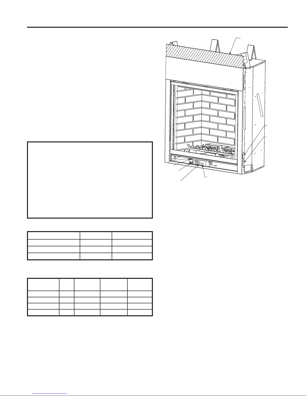
Insulation Board
Ignitor
On/Off/RS
Switch
Off/Pilot/On Knob
Figure 1 MLDV Series Fireplace (Millivolt Control shown)
Hi/Lo Knob
5/8" Nailing
Flange
1/2" Nailing
Flange
GAS PRESSURES
Natural Propane (LP)
Inlet Minimum 4.5” w.c. 11.0” w.c.
Inlet Maximum 10.5” w.c. 13.0” w.c.
Manifold Pressure 3.5” w.c. 10.0” w.c.
GAS SPECIFICATIONS & ORIFICE SIZE
Max.Input Min. Input Orifi ce
Model Fuel BTU/h BTU/h Size
MLDV500NV Nat. 34,000 22,000 #33
MLDV500PV LP 34,000 27,000 1.8 mm
MLDV500NSC Nat. 34,000 22,000 #33
MLDV500PSC LP 34,000 27,000 1.8 mm
20306748
5
MLDV Series Gas Fireplace
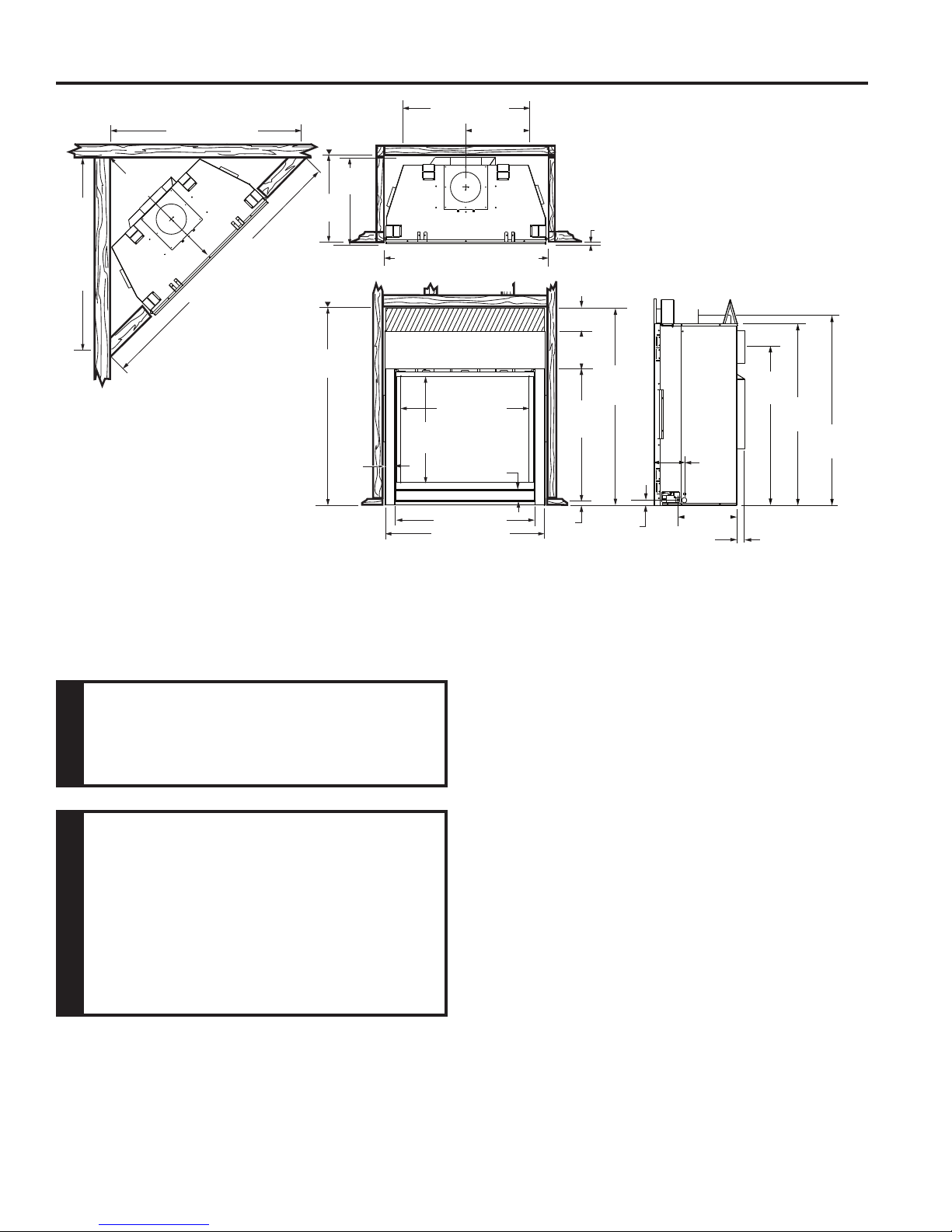
FIREPLACE AND FRAMING DIMENSIONS
5256M” (1327 mm)
3656M”
(921 mm)
5256M” (1327 mm)
7256O” (1791 mm)
(565 mm)
Min. Rough
Opening
Height
(1292 mm)
Figure 2 Fireplace and Framing Dimensions
Min. Rough
Opening
Depth
2256M”
(565 mm)
2256M”
50(6”
256O"
(64 mm)
30(6” (784 mm)
Min. Rough Opening Width
(4256O” 91080 mm)
33” (838 mm)
276QE”
(694 mm)
36” (914 mm)
41” (1041 mm)
206”
(524 mm)
1079.5 mm)
1080 mm)
356”
(79 mm)
6”
(152 mm)
9556QE”
(246 mm)
34”
(864 mm)
1”
(25 mm)
1/2” or 5/8”
506M”
(1289 mm)
156O”
(38 mm)
76”
(187 mm)
1456O”
(368 mm)
2”
(51 mm)
386M”
(984 mm)
446”
(1133 mm)
466”
(1184 mm)
Do not fill spaces around firebox with
insulation or other materials. This could
cause a fi re.
WARNING
COLD CLIMATE INSULATION
If you live in a cold climate, seal all cracks
around your appliance, and wherever cold air
could enter the room, with noncombustible
material. It is especially important to
NOTE
insulate the outside chase cavity between
the studs and under the fl oor on which the
appliance rests, if the fl oor is above ground
level.
NOTE: Refer to cold climate pilot information on Page 44
for more information on standing pilot vs. intermittent pilot
options.
6
20306748
PRE- INSTALLATION INFORMATION
MLDV Series Gas Fireplace
BEFORE YOU START
Read this homeowner manual thoroughly and follow all
instructions carefully. Inspect all contents for shipping
damage and immediately inform your dealer if any damage
is found. Do not install any unit with damaged, incomplete,
or substitute parts. Check your packing list to verify that
all listed parts have been received. You should have the
following:
• Fireplace (Firebox and Burner System)
• Log Set
• Rock Wool
ITEMS REQUIRED FOR INSTALLATION
Tools and Building Materials
• Phillips Screwdriver
• Hammer
• Saw and/or saber saw
• Measuring Tape
• Electric Drill and Bits
• Pipe Wrench
• Framing Materials
• Wall Finishing Materials
• Level
• Pliers
• Square
• Tee Joint
• Caulking Material (noncombustible)
• Fireplace Surround Material (noncombustible)
• Piping Complying with Local Codes
• Pipe Sealant Approved for use with Propane/LPG
(Resistant to sulfur compounds)
FIREBOX FRAMING
Firebox framing can be built before or after the appliance
is set in place. Construct fi rebox framing following Figure 2
for fi rebox and framing dimensions. The framing headers
may rest on the top of the fi rebox standoffs. Do not bring
headers below top of standoffs. NOTE: When planning
your framing and installation, keep in mind that your gas
line will come in on the right side of the box (as you are
facing it) and your electricity will come in on the left side.
The fi rebox may be installed directly on a combustible fl oor
or raised on a platform of an appropriate height. When
the fi rebox is installed directly on carpeting, tile, or other
combustible material, other than wood fl ooring, the fi rebox
shall be installed on a metal or wood panel extending the
full width and depth of the enclosure.
20306748
FIREPLACE LOCATION
Plan for the installation of your appliance. This includes
determining where the unit is to be installed, the vent
confi guration to be used, framing and fi nishing details,
and whether any optional accessories (i.e. blower, wall
switch, or remote control) are desired. Consult your local
building code agency to ensure compliance with local
codes, including permits and inspections.
The following factors should be taken into consideration:
• Clearance to side-wall, ceiling, woodwork, and windows.
Minimum clearances to combustibles must be main-
tained.
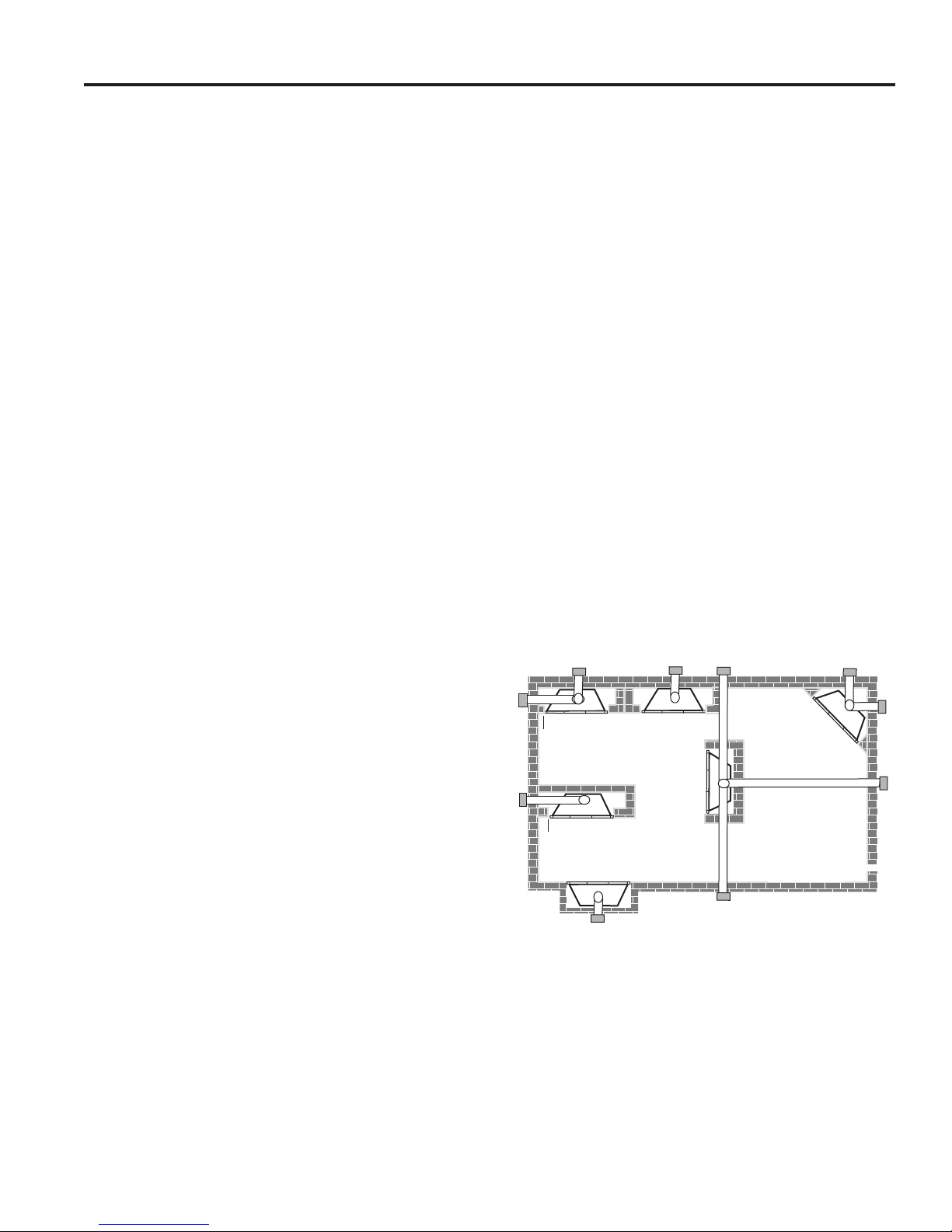
• This fi replace may be installed along a wall, across a
corner, or use an exterior chase. Refer to Figure 3 for
suggested locations.
• Location should be out of high traffi c areas and away
from furniture and draperies due to heat from appliance.
• Never obstruct the front opening of the fi replace.
• Do not install in the vicinity where gasoline or other
fl ammable liquids may be stored.
• Vent pipe routing. See Venting section found in this
manual for allowable venting confi gurations.
• These units can be installed in a bedroom. See National
Fuel Gas Code ANSI Z233.1/NFPA 54 — (current
edition), the Uniform Mechanical Code — (current edition), and Local Building Codes for specifi c installation
requirements.
• These units can be installed in a bathroom.
E
Y
D
Y
F
A Flat on Wall
B Cross Corner
C Island**
D Room Divider*
** Island (C) and room divider (D) installation is possible as long as
the horizontal portion of vent system (X) does not exceed 20'. See
Install Horizontal Termination Confi guration on Pages 18 and 19.
* When you install your fi replace in (D) room divider or (E) fl at on
wall corner positions (Y), a minimum of 6" clearance must be
maintained from perpendicular wall and front of fi replace.
Figure 3 Locate Gas Fireplace
A
C
E Flat on Wall Corner*
F Chase Installation
Y 6" Minimum
B
X
7
MLDV Series Gas Fireplace
CLEARANCES TO COMBUSTIBLES
Follow these instructions carefully to
ensure safe installation. Failure to follow
in struc tions exactly can create a fi re hazard.
The appliance cannot be installed on a
carpet, tile or other combustible material
other than wood fl ooring. If installed on
carpet or vinyl flooring, the appliance
WARNING
shall be installed on a metal, wood or
noncombustible material panel ex tend ing
full width and depth of the appliance.
Fireplace
Opening
Top View
256O"
CLEARANCES
Wall
Combustible
Material Area
1"
156O"
356O"
456O"
3"
5"
6"
45°
71” Minimum
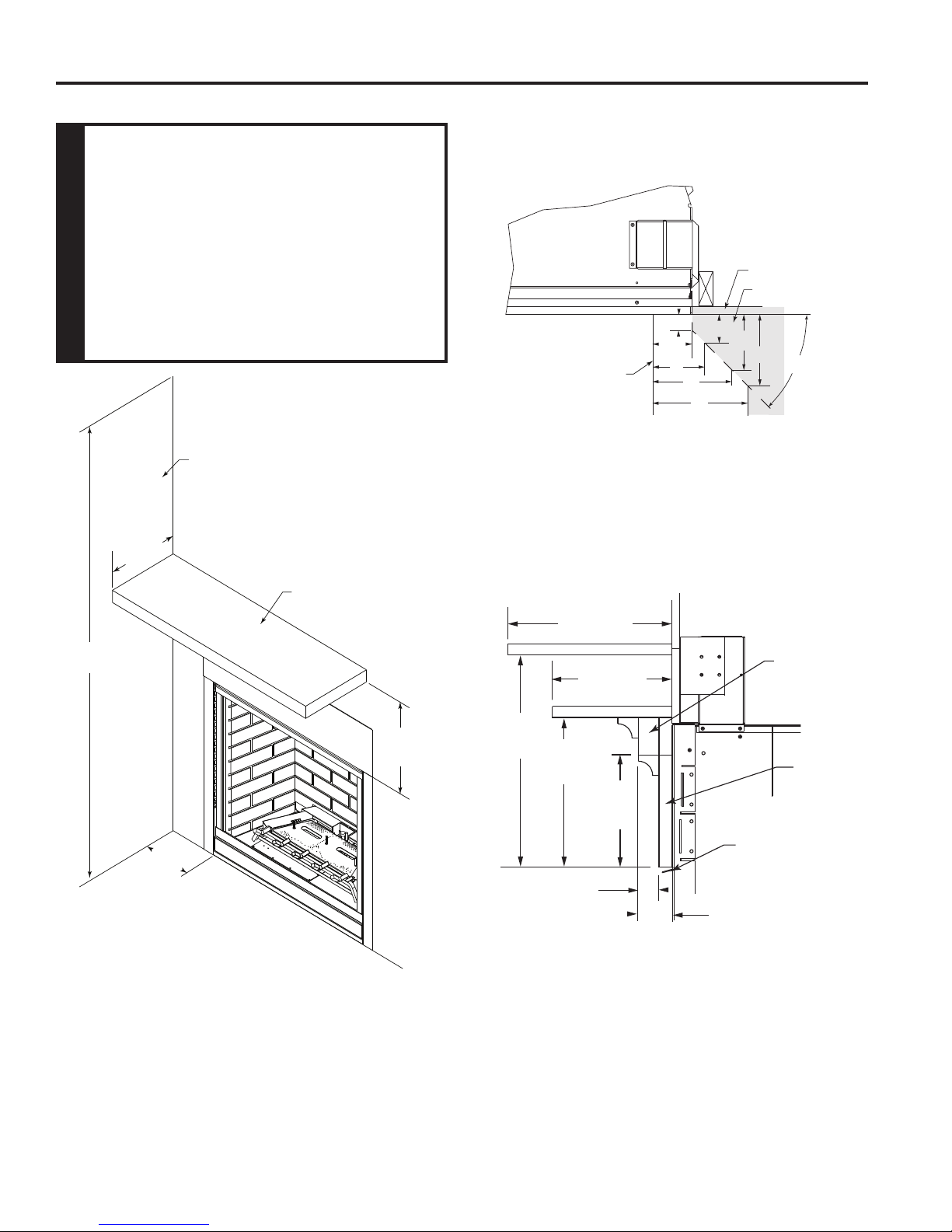
Ceiling
12” Max.
Depth
6” Min.
to Opening
Side Wall
Combustible
Mantel
14” Min.
From Opening
Figure 5 Mantel clearances.
12” Max.
8” Max.
14”
Min.
10”
Min.
156O”
Max.
Combustible
Breastplate
3/4"
Marble
756O”
Min.
Eyebrow
Canopy
256M” Max.
Figure 4 Side Wall and Ceiling Clearances
NOTE: When eyebrow canopy is used, minimum clearance to combustibles is 21⁄4" maximum out from fi replace front at
71⁄2" minimum from opening. Figure 5a. When eyebrow is not used, clearances to combustibles is 8" maximum out from
fi replace front at 10" minimum from opening or 12" maximum out from fi replace front at 14" minimum from opening. Figure 5
8
Figure 5a Mantel Clearance with Eyebrow Canopy
20306748
SECURE FIREPLACE TO FLOOR OR FRAMING
The fi replace must be secured to the fl oor and/or to framing
studs as shown in Figure 6. Use two (2) wood screws or
masonry/ concrete screws to secure fi replace to the fl oor.
Use four (4) screws to attach fi replace to framing. The side
nailing fl anges are 1/2" or 5/8" to accommodate different
wall thickness.
Framing
Screws
MLDV Series Gas Fireplace
DO NOT REMOVE INSULATION
BOARD
NOTE
Insulation Board
DO NOT REMOVE
Nailing Flange
Figure 6 Secure Fireplace to Floor and Framing Studs
FINISHING MATERIAL
NOTE: Any remote wiring (i.e. remote control, wall switch,
and optional fan) must be done prior to fi nal fi nishing to
avoid costly reconstruction.
Only noncombustible materials (i.e. brick, tile, slate, steel,
or other materials with a UL fi re rating of Zero) may be
used to cover the black painted face of the appliance. It is
permissible to bring combustible wall board to the top and
FP1989
side edges of the black painted face. A 300°F minimum
adhesive may be used to attach facing materials to the
black surface. If joints between the fi nished wall and the
fi replace surround are sealed, a 300°F minimum sealant
material (General Electric RTV103 or equivalent) must be
used.
20306748
9
MLDV Series Gas Fireplace
VENTING INSTALLATION
Read all instructions completely and
thoroughly before attempting installation.
Failure to do so could result in serious injury,
property damage or loss of life. Operation
of improperly installed and maintained
WARNING
venting system could result in serious injury,
property damage or loss of life.
Failure to follow these instructions
will void the warranty.
NOTICE
INSTALLATION PRECAUTIONS
Consult local building codes before beginning the
installation. The installer must make sure to select the
proper vent system for installation. Before installing vent
kit, the installer must read this fi replace manual and vent
kit instructions.
Only a qualifi ed installer/service person should install vent-
ing system. The installer must follow these safety rules:
• Wear gloves and safety glasses for protection.
• Use extreme caution when using ladders or when on
rooftops.
• Be aware of electrical wiring locations in walls and
ceilings.
The following actions will void the warranty on your venting
system:
• Installation of any damaged venting component.
• Unauthorized modifi cation of the venting system.
• Installation of any component part not manufactured
or approved by Vermont Castings Group.
• Installation other than permitted by these instructions.
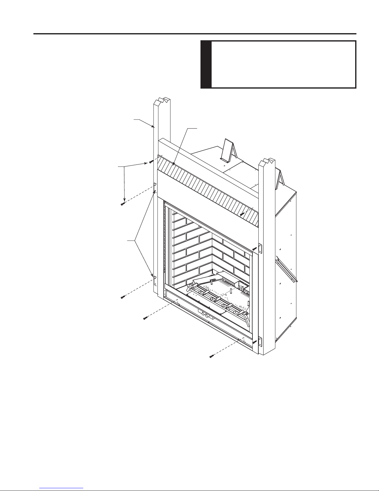
Screws
Flue Pipe
Cover
Flue Pipe
Adapter
Figure 7 Remove 16 screws from Flue Pipe Adapter and Flue Pipe
Cover
3. Remove the eight (8) screws securing the fl ue pipe cover
to the top of the intake box and remove the cover and
gasket. Figure 7
4. Remove six (6) screws securing the fl ue pipe to the
back of the intake box and remove the pipe and gasket.
Figure 8
5. Replace the fl ue pipe to top of fi rebox. Ensure the gasket
is in place and undamaged. Secure with six (6) screws.
Figure 9
6. Place the fl ue pipe cover and gasket removed in Step
3 over the fl ue opening in bottom of the intake box.
7. Refi t the fl ue pipe adapter and gasket to the top of fi re-
place. Secure the adapter with six (6) screws removed
in Step 1.
FP1991
OPTIONAL TOP VENT APPLICATION
The appliance is shipped as a rear vent unit. If the installation layout requires the unit to be a top vent confi guration,
the appliance can be converted by following the steps
below.
When removing and refi tting the plates and adapter, be
sure the associated gaskets are undamaged and refi tted
as required.
1. Remove the eight (8) screws securing the fl ue pipe
adapter to the fi replace body. Figure 7
2. Set the fl ue pipe adapter aside, complete with the
gasket. Do not damage the gaskets as the adapter and
gasket must be refi tted.
10
After conversion to top vent confi guration,
the 5" (127 mm) flue pipe should be
concentric with the 8" (203 mm) outer collar
within 1/4".
WARNING
This fireplace must be vented to the
outside. The venting system must NEVER
be attached to a chimney serving a separate
solid fuel burning appliance. Each gas
appliance must use a separate vent system.
WARNING
Do not use common vent systems.
20306748
VENTING INSTALLATION
Flue Cover
Flue Pipe
MLDV Series Gas Fireplace
Screws
*3”
**1”
**1”
Figure 8 Remove Flue Pipe
Flue Pipe
Screws
Figure 9 Attach Flue Pipe to Top Vent Confi guration
FP1992
*3”
**1”
**1”
FP1993
* A minimum of 3" clearance to the top is required along horizontal
length until fl ue pipe penetrates outside wall.
** A minimum 1" clearance to combustibles permitted all around
fl ue at outside wall
20306748
Figure 10 Combustible Clearances for Vent Pipe
11
MLDV Series Gas Fireplace
VENTING INSTALLATION
WARNING
Horizontal sections of this vent system require a
minimum of 3" clearances to combustibles at the top
of the fl ue and 1" clearance at the sides and bottom
until the fl ue penetrates the outside wall. A minimum
1" clearance all around the fl ue is acceptable at
this point of penetration. If vertical rise is 7
feet or higher when top venting, the clearance to
combustibles is 1" on all sides of the horizontal run.
Vertical sections of this vent system require a
minimum of 1" clearance to combustibles on all
sides of the pipe.
1
⁄2"
WARNING
Read all instructions completely and thoroughly
before attempting installation. Failure to do so
could result in serious injury, property damage or
loss of life. Operation of improperly installed and
maintained venting system could result in serious
injury, property damage or loss of life.
INSTALLATION PLANNING
There are two basic types of direct-vent installation:
• Horizontal Termination
• Vertical Termination
It is important to select the proper length of vent pipe for
the type of termination you choose. It is also important to
note the wall thickness.
FOR HORIZONTAL TERMINATION
Select the amount of vertical rise desired. All horizontal run
of venting must have 1/4" rise for every 12" of run towards
the termination below 71/2 feet of vertical rise. With 71/2 feet
or more vertical rise off top of fi replace, the horizontal run
may run level. NEVER run vent piping downward.
You may use up to three 90° elbows in this vent confi gu-
ration. Refer to Horizontal Termination Confi gurations on
Pages 17 and 18.
FOR VERTICAL TERMINATION
Measure the distance from the fi replace fl oor to the ceil-
ing. Add the ceiling thickness, the vertical rise in an attic
or second story, and allow for suffi cient vent height above
the roof line.
NOTE: You may use two 45° elbows in place of a 90° elbow.
You must follow rise to run ratios when using 45° elbows.
The appliance is approved for use with three 90° elbows
maximum or a combination of 90° and 45° elbows up to a
maximum of 270°.
For two-story applications, fi restops are required at each
fl oor level. If an offset is needed in the attic, additional pipe
and elbows will be required.
WARNING
Never run the vent pipe down. This may cause
excessive temperatures which could cause a fi re.
WARNING
Treatment of fi restops and construction of the chase
may vary from building type to building type. These
instructions are not substitutes for the requirements
of local building codes. You must follow all local
building codes.
NOTICE
When installing in a chase, you should insulate
the chase as you would the outside walls of
your home. This is especially important in cold
climates. Insulation should be considered a
combustible material. Maintain proper clearances
to all combustible materials.
You may use a chase with a vent termination with exposed
pipe on the exterior of the house. Refer to Installing Vent
System in a Chase below. If pipe is enclosed in chase, it
is not exposed.
It is very important that the venting system maintain its
balance between the combustion air intake and the fl ue
gas exhaust. Certain limitations apply to vent confi gurations
and must be strictly followed.
INSTALLING A VENT SYSTEM IN AN
OUTSIDE CHASE
A chase is a vertical boxlike structure built to enclose
venting that runs along the outside of a building. A chase
is required for such venting.
WARNING
Always maintain minimum clearances around vent
systems. The minimum clearance to combustibles
for horizontal vent pipe are 3" at the top and 1" at the
sides and bottom of the vent system until the pipe
penetrates the nearest vertical wall (1" required). A
1" minimum clearance all around the pipe must be
maintained at outside wall and on vertical runs. Do
not pack the open air spaces with insulation or other
materials. This could cause high temperatures and
may present a fi re hazard.
*Unless the vertical run is 71⁄2 feet or higher (top vent
units only), the clearances for the horizontal run is
1" at the top.
12
20306748
VENTING INSTALLATION
V
X
X
X
D
E
B
B
B
C
B
M
B
A
J
K
F
L
VENT TERMINATION AIR SUPPLY INLET
AREA WHERE TERMINAL IS NOT PERMITTED
H
I
Fixed
Closed
Operable
Operable
Fixed
Closed
B
INSIDE
CORNER DETAIL
A
G
CFM145a
V
V
V
V
V
V
V
V
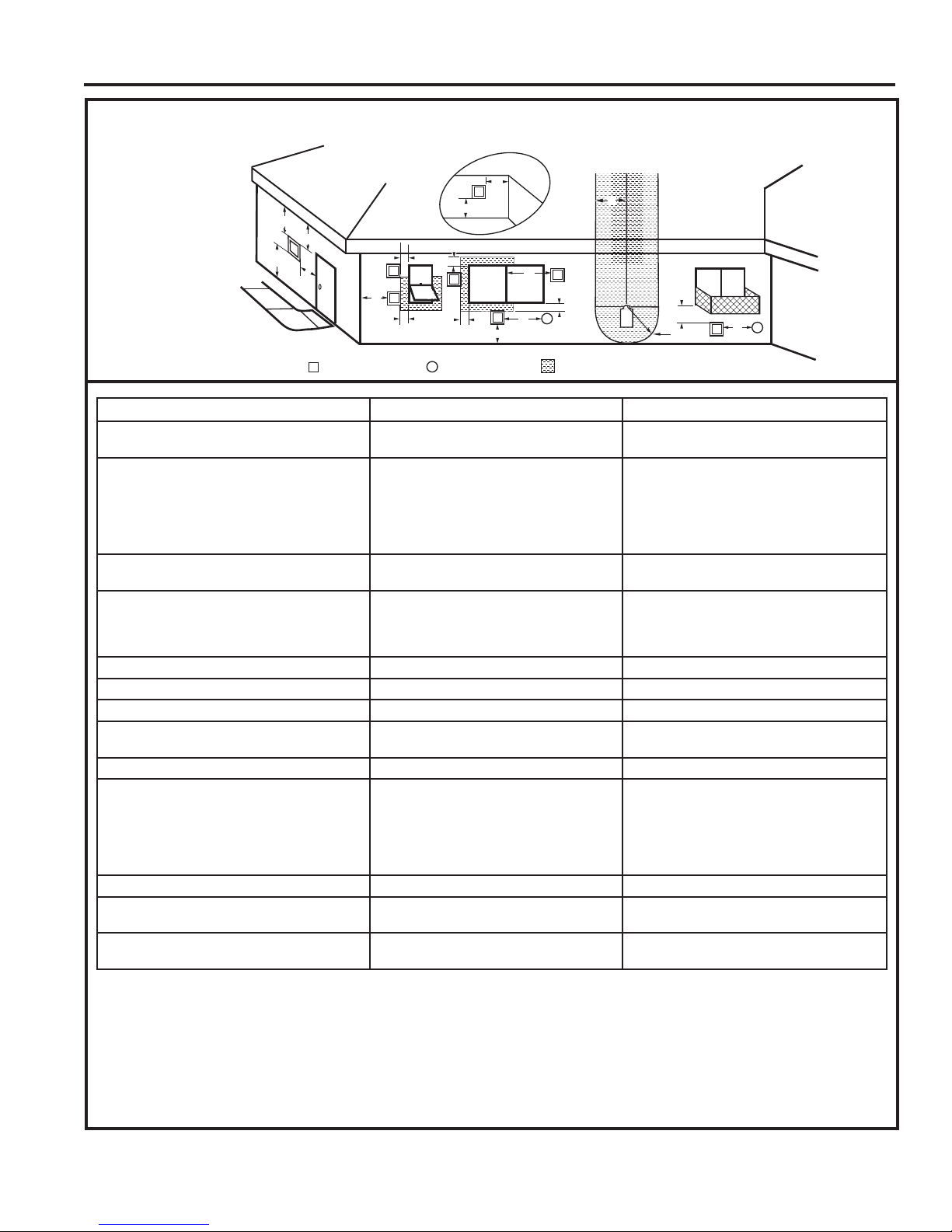
TERMINATION LOCATION
Figure 11 –
Termination Locations
MLDV Series Gas Fireplace
A = Clearance above grade, veranda, porch,
CANADIAN INSTALLATIONS
1
12" (30cm) 12" (30cm)
US INSTALLATIONS
2
deck or balcony
B = Clearance to window or door that may be
opened
C = Clearance to permanently closed window 12" (305mm) recommended to prevent
D = Vertical clearance to ventilated soffi t
6" (15cm) for appliances <10,000 BTU/h
(3kW)
12" (30cm) for appliances >10,000 BTU/h
(3kW) and <100,000 BTU/h (30kW)
36" (91cm) for appliances >100,000 BTU/h
(30kW)
6" (15cm) for appliances <10,000 BTU/h
(3kW)
9" (23cm) for appliances >10,000 BTU/h
(3kW) and <50,000 BTU/h (15kW)
12" (30cm) for appliances >50,000 BTU/h
(15kW)
12" (305mm) recommended to prevent
window condensation
window condensation
18" (458mm) 18" (458mm)
located above the terminal within a horizontal distance of 2' (610 mm) from the
center line of the terminal
E = Clearance to unventilated soffi t 12" (305mm) 12" (305mm)
F = Clearance to outside corner see next page see next page
G = Clearance to inside corner see next page see next page
H = Clearance to each inside of center line
extended above meter/regulator assembly
3' (91cm) within a height of 15' (5m) above
the meter/regulator assembly
3' (91cm) within a height of 15' (5m) above
the meter/regulator assembly
I = Clearance to service regulator vent outlet 3' (91cm) 3' (91cm)
J = Clearance to non-mechanical air supply
inlet to building or the combustion air inlet
to any other appliance
6" (15cm) for appliances <10,000 BTU/h
(3kW)
12" (30cm) for appliances >10,000 BTU/h
(3kW) and <100,000 BTU/h (30kW)
36" (91cm) for appliances >100,000 BTU/h
(30kW)
6" (15cm) for appliances <10,000 BTU/h
(3kW)
9" (23cm) for appliances >10,000 BTU/h
(3kW) and <50,000 BTU/h (15kW)
12" (30cm) for appliances >50,000 BTU/h
(15kW)
K = Clearance to mechanical air supply inlet 6' (1.83m) 3' (91cm) above if within 10' (3m) horizontally
L = Clearance above paved sidewalk or
7' (2.13m)
†
7' (2.13m)
†
paved driveway located on public property
M = Clearance under veranda, porch, deck or
12" (30cm)
‡
12" (30cm)
‡
balcony
1 In accordance with the current CSA-B149 Installation Codes
2 In accordance with the current ANSI Z223.1/NFPA 54 National Fuel
Gas Codes
† A vent shall not terminate directly above a sidewalk or paved
driveway which is located between two single family dwellings and
serves both dwellings
‡ Only permitted if veranda, porch, deck or balcony is fully open on a
minimum 2 sides beneath the fl oor.
20306748
NOTE: 1. Local codes or regulations may require different
2. The special venting system used on Direct Vent
3. Vermont Castings Group assumes no responsibility for
clearances.
Fireplaces are certifi ed as part of the appliance, with
clearances tested and approved by the listing agency.
the improper performance of the appliance when the venting
system does not meet these requirements.
13
MLDV Series Gas Fireplace
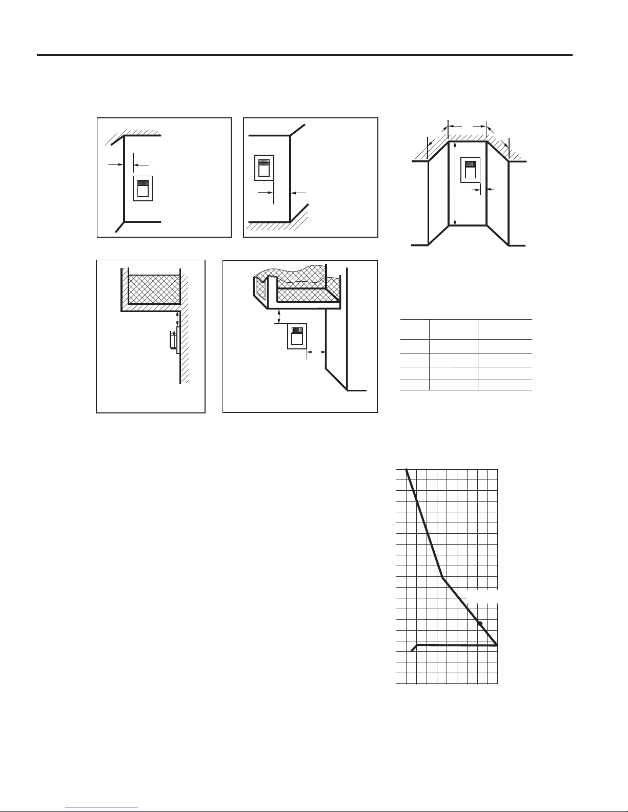
TERMINATION CLEARANCES
Termination clearances for buildings with combustible and non-combustible exteriors.
VENTING INSTALLATION
Inside Corner
G
V
Balcony -
with no side wall
M =
Combustible &
Noncombustible
12" (305 mm)
G =
Combustible
6" (152 mm)
Noncombustible
2" (51 mm)
M
V
Outside Corner
F =
Combustible
6" (152 mm)
F
Noncombustible
2" (51 mm)
V
Balcony -
with perpendicular side wall
M
V
P
Combustible &
Noncombustible
M = 12" (305 mm)
P = 6” (152 mm)
Alcove Applications*
D
C
O
C
V
E
E = Min. 2” (51 mm) for
non-vinyl sidewalls
Min. 12” (305 mm) for
vinyl sidewalls
O = 8’ (2.4 m) Min.
No. of
Caps DMIN. CMAX.
1 3' (914 mm) 2 x D
2 6' (1.8 m) 1 x DACTUAL
3 9' (2.7 m) 2/3 x DACTUAL
4 12' (3.7 m) 1/2 x DACTUAL
DMin. = Number of Termination caps x 3
CMax. = (2 / Number termination caps) x DActual
ACTUAL
*NOTE: Termination in an alcove space (spaces open only on one side
and with an overhang) is permitted with the dimensions specifi ed for
vinyl or non-vinyl siding and soffi ts. 1. There must be a 3' (914 mm) min-
imum between termination caps. 2. All mechanical air intakes within 10'
Figure 12 Allowable Venting
HOW TO USE THE VENT GRAPH
The Vent Graph should be read in conjunction with the
following vent installation instructions to determine the
relationship between the vertical and horizontal dimensions
of the vent system.
1. Determine the height of the center of the horizontal vent
pipe exiting through the outer wall. Using this dimension
on the Sidewall Vent Graph below, locate the point
intersecting with the slanted graph line.
2. From the point of this intersection, draw a vertical line
to the bottom of the graph.
3. Select the indicated dimension, and position the fi re-
place in accordance with same.
Example: If the vertical dimension from the fl oor of the
fi replace is 11' (3.4 m) the horizontal run to the face of
the outer wall must not exceed 16' (4.9 m).
Sidewall Vent Graph showing the relationship between
vertical and horizontal dimensions for a Direct Vent fl ue
system.
(1 m) of a termination cap must be a minimum of 3' (914 mm) below the
termination cap. 3. All gravity air intakes within 3' (914 mm) of a termination cap must be a minimum of 1' (305 mm) below the termination cap.
Dimensions in Feet
40
38
36
34
32
30
28
26
24
22
20
18
16
14
12
10
8
6
4
2
2 4 6 8 10 12 14 16 18 20
eg: A
Vertical Dimension From the Floor of Unit to the
Center of the Horizontal Vent Pipe
Horizontal dimension from the fi nished outside wall to the
center of the pipe on the fi replace
Figure 13 Rear Wall Venting Graph (No Horizontal Elbows)
14
20306748
VENTING INSTALLATION
MLDV Series Gas Fireplace
REAR WALL VENT INSTALLATION (5" x 8"
VENTING ONLY)
When installed as a rear vent unit, this appliance may be
vented directly to a termination located on the rear wall
behind the appliance. Only an Vermont Castings Group
brand termination is allowed for this application.
• The maximum horizontal distance between the rear
of the appliance and the termination is 20" (508 mm).
Figure 14
Maximum
20"
Top View Flat Installation
Figure 14 - Rear Vent Application, Maximum Horizontal
Distance
•
Only one 45 degree elbow is allowed in these installations.
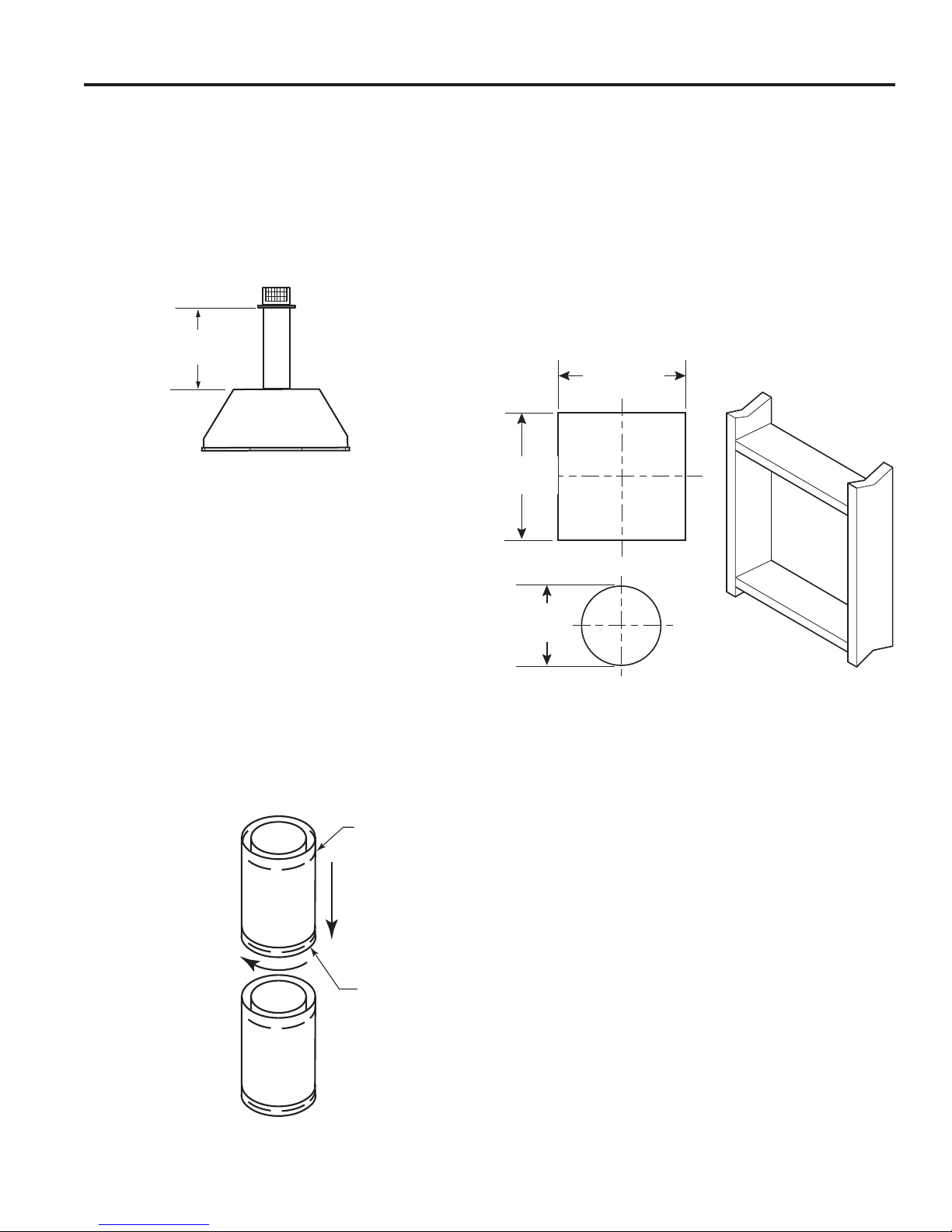
1. Rigid vent pipes and fi ttings have special twist-lock
connections. Assemble the desired combination of pipe
and elbows to the appliance adapter.
Twist-Lock Procedure: The female ends of the pipes
and fi ttings have three (3) locking lugs (indentations).
These lugs will slide straight into matching slots on
the male end of adjacent pipes and fi ttings. Push the
pipe sections together and twist one section clockwise
approximately one-quarter turn until the sections are
fully locked. Figure 15
NOTE: Sealant is not required to assemble fi replace
venting. Do not use silicone sealant at the inner fl ue
exhaust connections.
Female Locking
Lugs
NOTE: Horizontal
runs of vent must
be supported every
three feet (914 mm).
Use wall straps for
this purpose.
Male Slots
Figure 15 Rigid Vent Pipe Connections
20306748
2. Refer to venting and termination instructions for further
instructions.
3. Locate and cut the vent opening in the wall. For combustible walls fi rst frame in opening.
Combustible Interior Walls: Cut a 12
1
/2" x 101/2" hole
through the interior wall.
Combustible Exterior Walls: Cut a 101/2" x 101/2"
square hole through the exterior wall frame. Figure 16
Noncombustible Walls: Hole opening should be 81/2"
(216 mm) in diameter.
4. The center of the hole should align with the center line
of the horizontal rigid vent pipe end. Allow 1/4" minimum
rise per foot. Figure 16
101/2"
(267 mm)
101/2"
(267 mm)
Combustible Wall
81/2"
(216 mm)
Noncombustible
Wall
Figure 16 Exterior Wall Framing Dimensions
FP1954
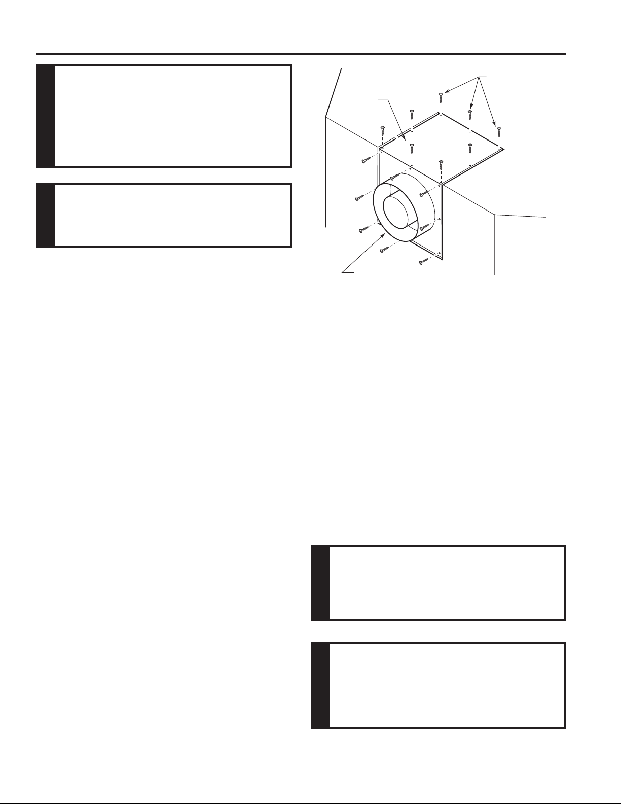
5. Apply a bead of non-hardening mastic around the
outside edge of vent cap. Position the vent cap in the
center of hole on the exterior wall with the word "UP"
on the vent cap facing up. Insure proper clearance of
1" to combustibles is maintained. Attach the vent cap
with four (4) wood screws supplied. Figure 17
NOTE: Replace the wood screws with appropriate
fasteners for stucco, brick, concrete or other types
of siding.
For vinyl siding, stucco or wood exterior, use vinyl
siding standoffs between vent cap and exterior wall for
Duravent or Selkirk Terminations only. The vinyl siding
standoff prevents excessive heat from melting the
vinyl siding material. NOTE: Vermont Castings Group
Termination does not require standoff. Bolt the vent
cap to the standoff or wall. Apply non-hardening mastic
around outside edge of the standoff instead of the vent
cap assembly. Use wood screws provided to attach the
standoff. Figure 18
15

MLDV Series Gas Fireplace
HOT
Vent Cap
Vent Cap
(Horizontal
Termination)
VENTING INSTALLATION
Interior Wall
Surface
Firestop
Apply Mastic to all
Four Sides
Figure 17 Install Horizontal Termination
Apply
Mastic to
all Four
Sides
FP1956
Figure 18 Install Duravent/Selkirk Vinyl Siding Standoff and
Termination
Nut
Wood Screw
Wood Screw
Cut Vinyl Siding Away
to Fit Standoff
Standoff #1250 or
5DT-VS
(Not required for Vermont Castings Group
termination)
Termination
HOT
Bolt
6. Slide the stop over the vent pipe before connecting the
horizontal run to the vent cap. Figure 19
7. Carefully move the fireplace with vent assembly
attached toward the wall and insert the vent pipe into
the horizontal termination. The pipe overlap should
be a minimum of 11/4". Apply silicone to the outer pipe
connection. Fasten all vent connections with screws
provided.
8. Slide the wall thimble against the interior wall surface
and attach with screws. Figure 19
All rear vent through-the-wall applications
must use Vermont Castings Group-designed 5 x 8 square termination. No other
manufacturer's termination is permitted in
NOTICE
this application.
FP1957
Screw
Figure 19 Install Firestop on Horizontal Vent Pipe
Horizontal
Vent Pipe
Do not recess vent termination into any
wall. This will cause a fi re hazard.
WARNING
For more information, follow instructions
provided with terminations.
NOTICE
HORIZONTAL WITH VERTICAL RISE
(THROUGH-THE-WALL)
TERMINATION CONFIGURATIONS
Since it is very important that the venting system
maintain its balance between the combustion air
intake and the fl ue gas exhaust, certain limitations
as to vent confi gurations apply and must be strictly
adhered to.
The Vent Graph, showing the relationship between vertical
and horizontal side wall venting, will help to determine the
various dimensions allowable. Figure 13
Minimum clearance between vent pipes and combustible
materials is 3" on top and 1" from bottom and sides unless
otherwise noted (Exception: Outside wall with fi restop: 1"
all around pipes are allowed). If the vertical run is 71/2 feet
or more, off the top of the fi replace, the clearance is 1" on
all sides of the horizontal run.
When vent termination exits through foundations less than
20" below siding outcrop, the vent pipe must be fl ush with
the siding.
It i s best t o locate t he fi replace in such a way that minimizes
the number of offsets and horizontal vent length.
16
20306748
VENTING INSTALLATION
MLDV Series Gas Fireplace
The horizontal vent run refers to the total length of vent
pipe from the fl ue collar of the fi replace (or the top of the
Transition Elbow) to the face of the fi nished outside wall
or the mounting fl ange of the termination.
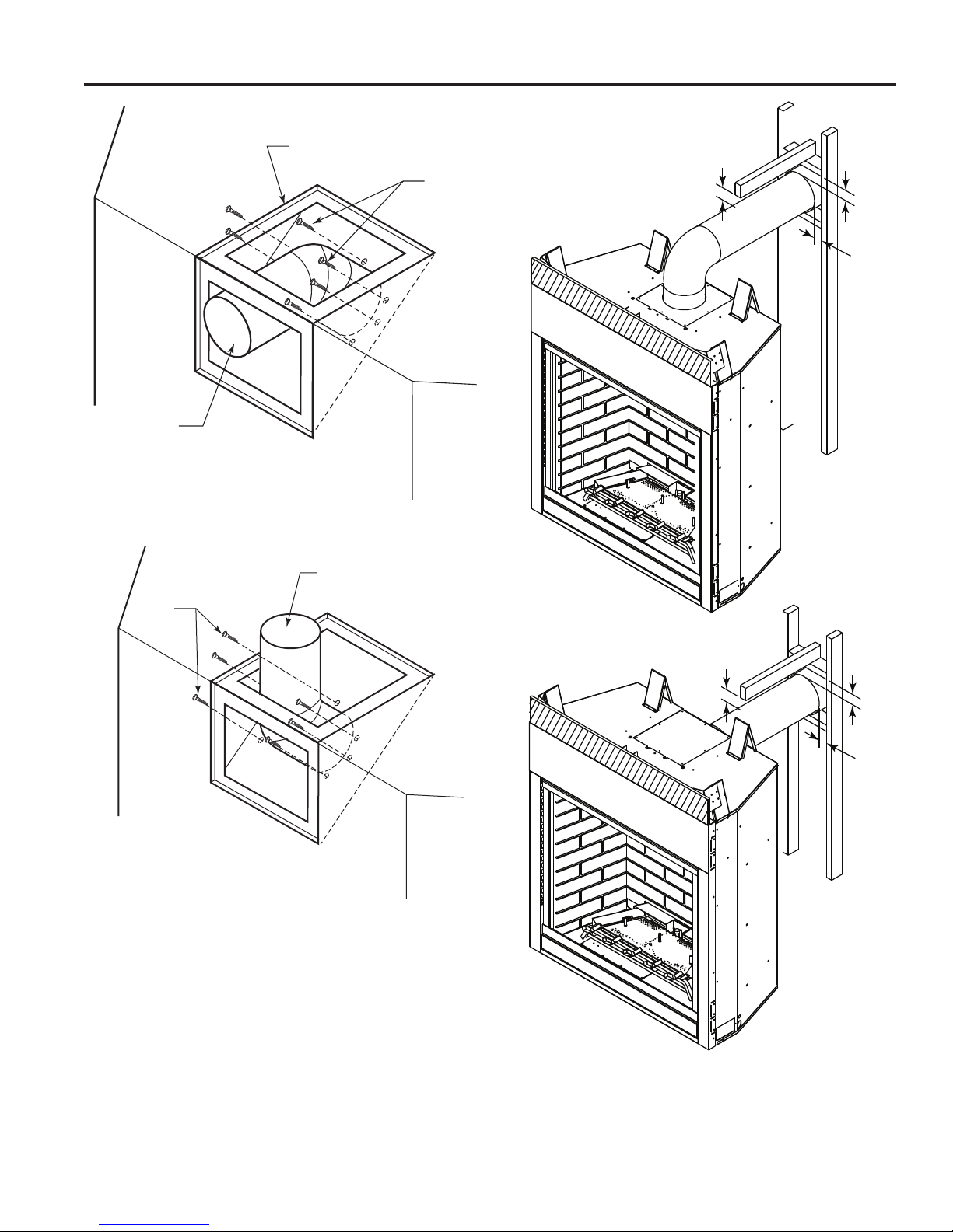
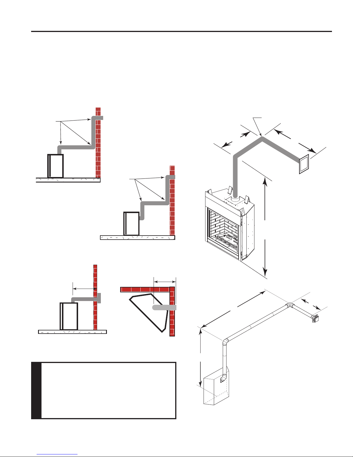
• The maximum number of 90° elbows per side wall
installation is three (3). Figure 20
• If a 90° elbow is fi tted directly on the top of the fi replace,
the maximum horizontal vent run before the termination
or a vertical rise is 36” (914 mm). Figure 21
3 x 90°
Elbows
3 x 90°
Elbows
• If a 90° elbow is used in the horizontal vent run (level
height maintained) the horizontal vent length is reduced
by 36". Figure 23. This does not apply if the 90° elbows
are used to increase or redirect a vertical rise. Figure
22
Example: According to the vent graph (Page 17) the
maximum horizontal vent length in a system with a 7.5'
vertical rise is 20’ (6 m) and if a 90° elbow is required in the
horizontal vent it must be reduced to 17' (5.2 m).
In Figures 22 and 23 dimension A plus B must not be
greater than 17' (5.2 m).
90°
A
B
Figure 20 Maximum Three (3) 90° Elbows
Per Installation
36"
(914 mm)
Max.
FP1177
Figure 21 Maximum Horizontal Run with No Rise
When installing the appliance as a rear
vent unit, the 90° or 45° transition elbow
attached directly to the rear of the unit is
NOT INCLUDED in the following criteria
and calculations and, unless specifi cally
mentioned, should be ignored when
WARNING
calculating venting layouts.
FP1176
36"
(914 mm)
Max.
7'6"
FP1958
Figure 22 Horizontal Run Reduction
A
10'
Horizontal 90° Elbow = 3' Reduction
7'6"
A + B = 17' Maximum
Figure 23 Maximum Vent Run with Elbows
B
7'
20306748
17
MLDV Series Gas Fireplace
VENTING INSTALLATION
• For each 45° elbow installed in the horizontal run, the
length of the horizontal run MUST be reduced by 18"
(457 mm). This does not apply if the 45° elbows are
installed on the vertical part of the vent system.
• The maximum number of elbow degrees in a system is
270°. Figure 24
Example: Elbow 1 = 90°
Elbow 2 = 45°
Elbow 3 = 45°
Elbow 4 = 90°
Total Angular Variation = 270°
1
2
3
4
1 + 2 + 3 + 4 = 270°
Figure 24 Maximum Elbow Usage
1
2
3
4
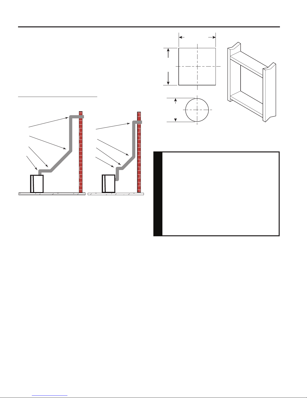
101/2"
(267 mm
101/2"
(267 mm
Figure 25 Exterior Wall Framing Dimensions for 5" x 8"
)
81/2"
(216 mm
Combustible
)
Noncombustible
)
Wall
Wall
You may use a reducer from 5" x 8" to 4" x
65⁄8" or 4" x 7" for horizontal with vertical rise
applications. ONLY use framing instructions
below when using 4" x 65⁄8" or 4" x 7" venting.
If the reducer is installed at the rear of the
unit, you must immediately follow with a 90
elbow for a vertical rise before continuing
with any horizontal run. There is a minimum
WARNING
total height of 7 feet from the fi replace fl oor
to the last section of pipe before horizontal
run. Refer to graph on Page 17.
FP1954
VERTICAL SIDE WALL APPLICATIONS
For 5 x 8 Venting
1. Locate and cut the vent opening in the wall. For
combustible walls fi rst frame in opening.
Combustible Interior Walls: Cut a 121⁄2"H x 101⁄2" W
hole through the interior wall.
Combustible Exterior Walls: Cut a 101⁄2"H x 101⁄2"W
square hole through the exterior wall frame. Figure 25
Noncombustible Walls: Hole opening should be 81⁄2"
(216 mm) in diameter.
2. The center of the hole should line up with the center line
of the horizontal rigid vent pipe end. Allow 1/4" minimum
rise per foot. Figure 25
NOTE: #1222DA reducer must be used when 4x6
venting is preferred. The 7TDVP58 reducer must be
used when 4" x 7" venting is preferred. Reducer must
be installed directly onto unit at the fi replace collar
before vertical rise.
18
5
⁄8"
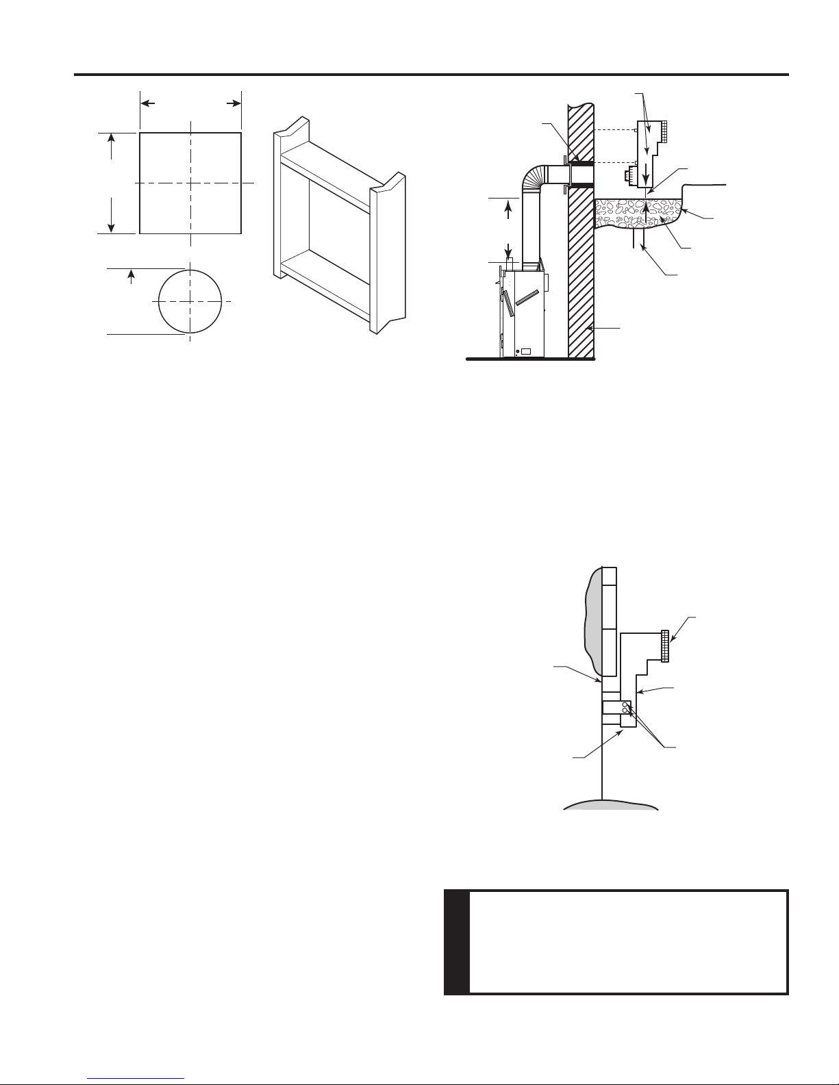
For 4 x 7 (or 4 x 65⁄8) Venting
1. Locate and cut the vent opening in the wall. For combustible walls fi rst frame in opening.
Combustible Interior Walls: Cut a 111⁄2"H x 91⁄2" W hole
through the interior wall.
Combustible Exterior Walls: Cut a 91⁄2"H x 91⁄2"W
square hole through the exterior wall frame. Figure 26
Noncombustible Walls: Hole opening should be 71⁄2"
(190 mm) in diameter.
2. The center of the hole should line up with the center line
of the horizontal rigid vent pipe end. Allow 1/4" minimum
rise per foot. Figure 26
20306748
VENTING INSTALLATION
MLDV Series Gas Fireplace
91/2"
(241 mm
91/2"
71/2"
(190 mm
)
Combustible
)
Noncombustible
(241 mm
Figure 26 Exterior Wall Framing Dimensions for 4" x 65/8" or 4" x 7"
)
Wall
FP1954
Wall
BELOW GRADE INSTALLATIONS
When it is not possible to meet the required vent terminal
clearances of 12" above grade level, a snorkel kit is recommended. It allows installation depth down to 7" (178
mm) below grade level. The 7" (178 mm) is measured
from the center of the horizontal vent pipe as it penetrates
through the wall.
Ensure that sidewall venting clearances are observed.
If venting system is installed below ground, we recommend a window well with adequate and proper drainage
to be installed around the termination area.
If installing a snorkel, a minimum 24" vertical rise is necessary. The maximum horizontal run with the 24” vertical
pipe is 36". This measurement is taken from the collar of
the fi replace (or transition elbow) to the face of the exterior
wall. Refer to the Sidewall Venting Graph for extended
horizontal run if the vertical exceeds 24".
1. Establish vent hole through the wall.
2. Remove soil to a depth of approximately 16" below base
of snorkel. Install drain pipe. Install window well (not
supplied). Refi ll hole with 12" of coarse gravel leaving
a clearance of approximately 4" below snorkel. Figure
27
3. Install vent system.
4. Ensure a watertight seal is made around the vent pipe
coming through the wall.
5. Apply high temperature sealant caulking (supplied)
around the 5" and 8" snorkel collars.
6. Slide the snorkel into the vent pipes and secure to the
wall.
7. Level the soil so as to maintain a 4" clearance below
snorkel. Figure 27
Screws
Firestop
Minimum
4" Clearance
Ground
12"
Minimum
Foundation Wall
Figure 27 -
Below Grade Installation
Window Well
Gravel
Drain
If the foundation is recessed, use recess brackets (not
supplied) for securing lower portion of the snorkel. Fasten
brackets to wall fi rst, then secure to snorkel with self drilling
#8 x 1/2 sheet metal screws. It will be necessary to extend
vent pipes out as far as the protruding wall face. Figure 28
Snorkel
Foundation
Recess
Wall Screws
Watertight Seal
Around Pipe
FP1966
Figure 28 Snorkel Installation, Recessed Foundation
Sheet Metal
Screws
• Do not back fi ll around snorkel.
• A clearance of at least 4” must be
maintained between the snorkel and the
soil.
WARNING
20306748
19
MLDV Series Gas Fireplace
VENTING INSTALLATION
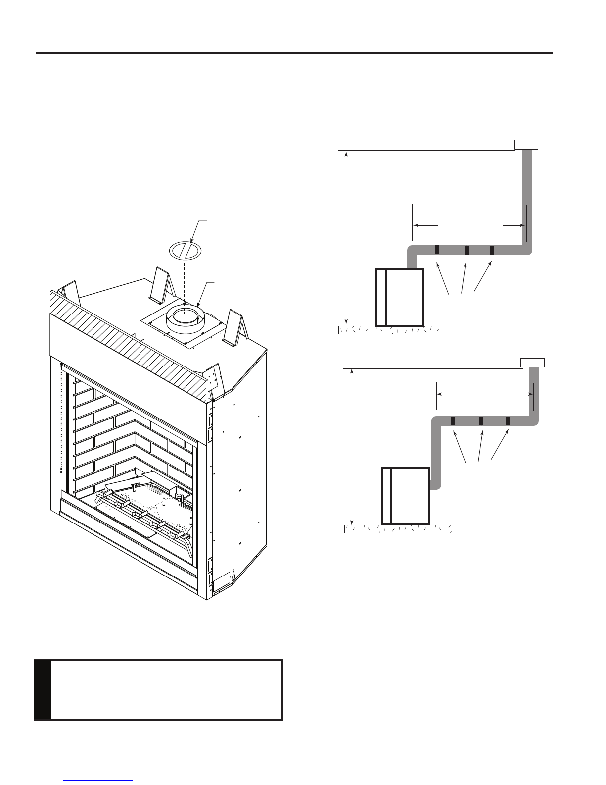
VERTICAL THROUGH-THE-ROOF APPLICATIONS
Install restrictor disc as shown in Figure 29 for vertically
vented applications.
Up to two (2) restrictor discs may be needed for 40' installation.
The two (2) restrictor discs suppled will work for most installations. If a third disc is needed order Part No. 56D3027.
You may use a reducer to 4" x 6
vented applications. If a reducer is used, only one restrictor
may be used.
5
⁄8" or 4" x 7" in vertically
Restrictor Disc
Fireplace Collar
This Gas Fireplace has been approved for,
• Vertical installations up to 40' (12 m) in height. Up to
a 10' (3 m) horizontal vent run can be installed within
the vent system using a maximum of two 90° elbows.
Figure 30
Maximum Height
40' (12 m)
Minimum Height
8' (2 m)
10' (3 m)
Maximum
Support Straps
Every 3' (914 mm)
Figure 29 Install Restrictor Disc into Fireplace Collar
A restrictor disc must be installed on any
vertical termination that is higher than 12'.
NOTICE
10' (3 m)
Maximum
Maximum Height
40' (12 m)
Minimum Height
8' (2 m)
Support Straps
Every 3' (914 mm)
FP1183
Figure 30 Support Straps for Horizontal Runs
• Up to two 45° elbows may be used within the horizontal
run. For each 45° elbow used on the horizontal plane,
the maximum horizontal length must be reduced by 18"
(450 mm).
Example: Maximum horizontal length
No elbows = 10’ (3 m)
1 x 45° elbows = 8.5’ (2.6 m)
2 x 45° elbows = 7’ (2.1 m)
• A minimum of an 8' (2.5 m) vertical rise is required.
20
20306748
 Loading...