

Vermont Castings LX32DV(N/P)SB, LX36DV(N/P)SB Installation And Operating Instructions Manual
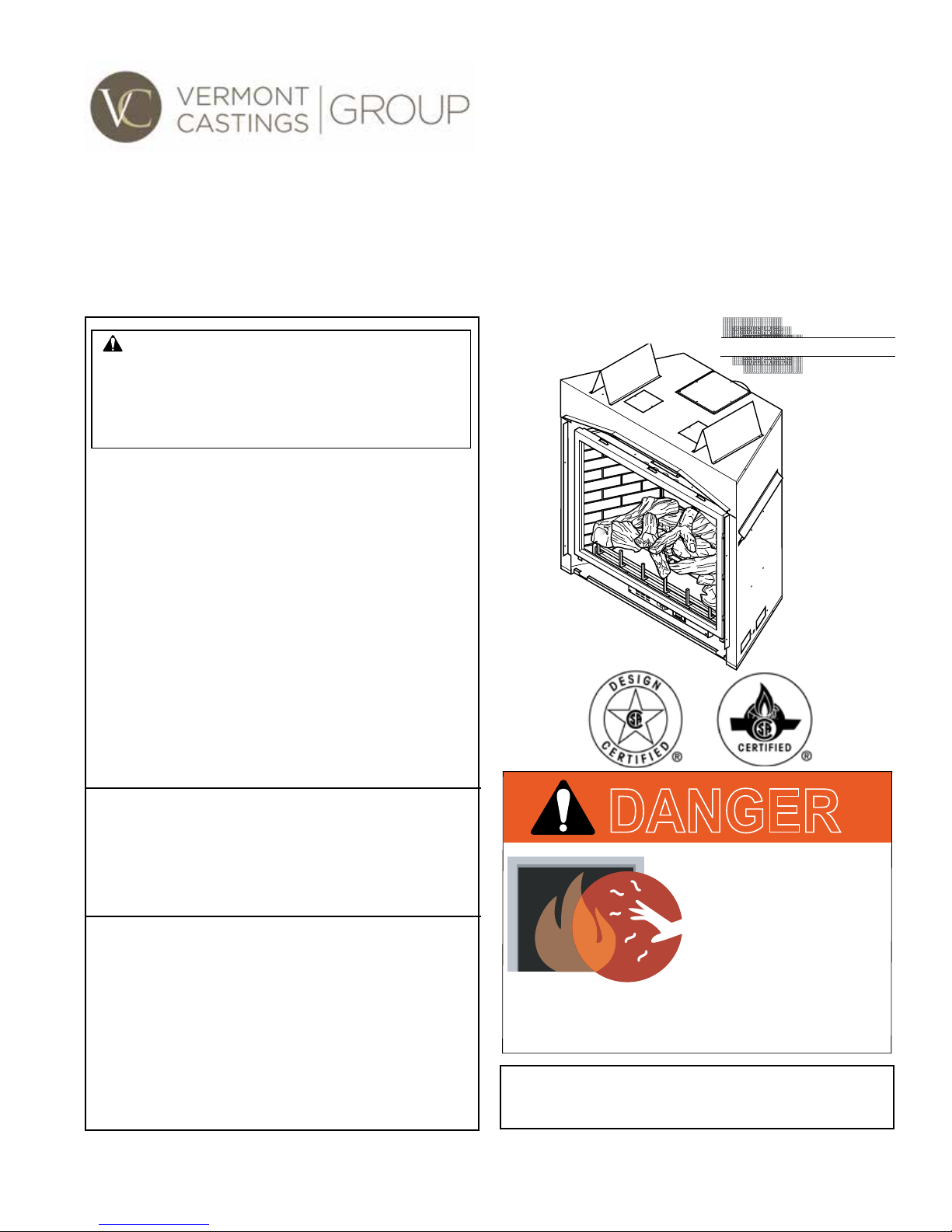
Lexington Direct Vent Gas Fireplace
S
Installation and Operating Instructions
Models: LX32DV(N/P)SB, LX36DV(N/P)SB
WARNING:
FIRE OR EXPLOSION HAZARD
Failure to follow safety warnings exactly
could result in serious injury, death or
property damage.
• Do not store or use gasoline or other
ammable vapors and liquids in the
vicinity of this or any other appliance.
• WHAT TO DO IF YOU SMELL GAS
– Do not try to light any appliance.
– Do not touch any electrical switch; do
not use any phone in your building.
– Leave the building immediately.
– Immediately call your gas supplier from
a neighbor's phone. Follow the gas
supplier's instructions.
– If you cannot reach your gas supplier,
call the re department.
• Installation and service must be performed
by a qualied installer, service agency or
the gas supplier.
WARNING: Improper installation, adjustment,
alteration, service or maintenance can cause
injury or property damage. Refer to this manual.
For assistance or additional information consult
a qualified installer, service agency or the
gas supplier.
This appliance may be installed in an aftermarket,*
permanently located, manufactured home (USA
only) or mobile home, where not prohibited by
local codes.
This appliance is for use only with the type of gas
indicated on the rating plate. This appliance is
not convertible for use with other gases, unless
a certied kit is used.
* Aftermarket: Completion of sale, not for purpose of resale, from
the manufacturer.
CERTIFIED
AFETY BARRIER
DANGER
HOT GLASS WILL
CAUSE BURNS.
DO NOT TOUCH GLASS
UNTIL COOLED.
NEVER ALLOW CHILDREN
TO TOUCH GLASS.
A barrier designed to reduce the risk of burns from
the hot viewing glass is provided with this
appliance and shall be installed.
INSTALLER: Leave this manual with the appliance.
CONSUMER: Retain this manual for
future reference.
20306749 12/14 Rev. 1

LX Series Direct Vent Gas Fireplace
Congratulations!
You have purchased a state-of-the-art gas appliance featuring the Lex-Fire® Burn System available
exclusively on Vermont Castings Group gas appliances.
®
The Lex-Fire
technology and ember placement. Each element affecting combustion and ame appearance was carefully
scrutinized and strategically balanced during the design process.
Burn System sets a new standard for ame appearance through innovative log design, burner
Important Safety Information .....................................3
Code Approval ..................................................................4
Product Features ..............................................................5
High Elevations ................................................................5
Gas Pressures..................................................................5
Gas Specications & Orice Size .....................................5
Fireplace & Framing Dimensions...............................6
Pre-Installation Information ........................................7
Before You Start ............................................................... 7
Fireplace Framing ............................................................7
Fireplace Location ............................................................8
Clearances .......................................................................9
Secure Fireplace to Floor or Framing.............................10
Finishing Material ...........................................................10
Venting Installation ....................................................11
Optional Top Vent Application .........................................11
Installation Precautions ..................................................12
Installation Clearances for Vent Pipe .............................13
Installation Planning .......................................................14
Horizontal Termination ....................................................14
Vertical Termination ........................................................14
General Information - Termination Location ...................15
How to Use the Vent Graph............................................16
Rear Wall Vent Installation .............................................17
Horizontal (Through the Wall) Termination ....................18
Below Grade Installation ................................................20
Vertical Through-the-Roof Installation ............................20
Installation for Vertical Termination .................................21
Fireplace Installation .................................................23
Check Gas Type .............................................................23
Install Gas Piping ...........................................................23
Checking Gas Pressure .................................................25
Electrical Installation.......................................................25
Electrical Wiring ..............................................................25
Remote Wall Switch .......................................................26
Glass Removal ...............................................................27
Log Placement ...............................................................27
Air Restrictor Adjustment ................................................ 31
Safety Barrier Installation ...............................................32
Facing Installation ..........................................................33
Operating Instructions ..............................................34
What To Do If You Smell Gas ......................................... 34
Lighting Pilot for the First Time .......................................34
Lighting Pilot ...................................................................35
Lighting Burner ...............................................................36
To Turn Off Gas ..............................................................36
Cleaning and Maintenance .......................................37
Venting System ..............................................................37
Cleaning Glass ...............................................................37
Pilot and Burner Flames .................................................37
Firebox Cleaning ............................................................37
Glass Replacement ........................................................38
Blower..........................................................................37
Troubleshooting .........................................................39
Replacement Parts .....................................................40
Optional Accessories .................................................42
Venting Components ..................................................43
Massachusetts Residents Only.................................46
Warranty ......................................................................47
Efciencies..................................................................48
2
20306749
IMPORTANT SAFETY INFORMATION
LX Series Direct Vent Gas Fireplace
INSTALLER
Please leave these instructions with the appliance.
OWNER
Please retain these instructions for future reference
• Read this owner’s manual carefully and completely before trying to assemble, operate,
or service this replace.
• Any change to this replace or its controls can be dangerous.
• Improper installation or use of this replace can cause serious injury or death from
re, burns, explosions, electrical shock and carbon monoxide poisoning.
WARNING
This replace is a vented product. This replace must be
properly installed by a qualied service person. The glass
door must be properly seated and sealed. If this unit is not
properly installed by a qualied service person with glass
door properly seated and sealed, combustion leakage
can occur.
CARBON MONOXIDE POISONING: Early signs of carbon
monoxide poisoning are similar to the u with headaches,
dizziness and/or nausea. If you have these signs, the re-
place may not have been installed properly. Get fresh air
at once! Have the replace inspected and serviced by a
qualied service person. Some people are more affected
by carbon monoxide than others. These include pregnant
women, people with heart or lung disease or anemia,
those under the inuence of alcohol, and those at high
altitudes.
Propane/LP gas and natural gas are both odorless. An
odor-making agent is added to each of these gases. The
odor helps you detect a gas leak. However, the odor added
to these gases can fade. Gas may be present even though
no odor exists.
Make certain you read and understand all warnings. Keep
this manual for reference. It is your guide to safe and proper
operation of this replace.
1. This appliance is only for use with the type of gas
indicated on the rating plate. This appliance is not
convertible for use with other gases unless a certied
kit is used.
2. For propane/LP replace, do not place propane/LP
supply tank(s) inside any structure. Locate propane/
LP supply tank(s) outdoors. To prevent performance
problems, do not use propane/LP fuel tank of less than
100 lbs. capacity.
3. If you smell gas
• shut off gas supply.
• do not try to light any appliance.
• do not touch any electrical switch; do not use any
phone in your building .
4. Never install the replace
• in a recreational vehicle
• where curtains, furniture, clothing, or other am-
mable objects are less than 42" from the front, top,
or sides of the replace
• in high trafc areas
• in windy or drafty areas
5. This replace reaches high temperatures. Keep children and adults away from hot surfaces to avoid burns
or clothing ignition. Fireplace will remain hot for a time
after shutdown. Allow surfaces to cool before touching.
6. Young children should be carefully supervised when
they are in the same room as the appliance. Toddlers,
young children and others may be susceptible to
accidental contact burns. A physical barrier is recommended if there are at risk individuals in the house. To
restrict access to a replace or stove, install an adjustable safety gate to keep toddlers, young children and
other at risk individuals out of the room and away from
hot surfaces.
7. Do not modify replace under any circumstances. Any
parts removed for servicing must be replaced prior to
operating replace.
8. Turn replace off and let cool before servicing, installing, or repairing. Only a qualied service person should
install, service, or repair the replace. Have burner
system inspected annually by a qualified service
person.
9. You must keep control compartments, burners, and
circulating air passages clean. More frequent cleaning
may be needed due to excessive lint and dust from
carpeting, bedding material, pet hair, etc. Turn off the
gas valve and pilot light before cleaning replace.
10. Have venting system inspected annually by a quali-
ed service person. If needed, have venting system
cleaned or repaired. See Cleaning and Maintenance,
Page 37.
• immediately call your gas supplier from a neigh-
bor’s phone. Follow the gas supplier’s instructions.
.
20306749
3

LX Series Direct Vent Gas Fireplace
IMPORTANT SAFETY INFORMATION
11. Keep the area around your replace clear of combustible materials, gasoline, and other ammable vapor
and liquids. Do not run replace where these are used
or stored. Do not place items such as clothing or deco-
rations on or around replace.
12. Do not use this replace to cook food or burn paper or
other objects.
13. Never place anything on top of replace.
14. Do not use any solid fuels (wood, coal, paper, card-
board, etc.) in this replace. Use only the gas type
indicated on rating plate.
15. This appliance, when installed, must be electrically
grounded in accordance with local codes or in the
absence of local codes, with the National Electrical
Code, ANSI/NFPA 70, or the Canadian Electrical Code,
CSA C22.1.
16. Do not obstruct the ow of combustion and ventilation
air in any way. Provide adequate clearances around
air openings into the combustion chamber along with
adequate accessibility clearance for servicing and
proper operation.
17. When the appliance is installed directly on carpeting,
tile or other combustible material other than wood
ooring, you must set appliance on a metal or wood
panel or hearth pad extending the full width and depth
of the appliance.
18. Do not use replace if any part has been exposed to
or under water. Immediately call a qualied service
person to arrange for replacement of the unit.
19. Do not operate replace if any log is broken.
20. Do not use a blower insert, heat exchanger insert, or
any other accessory not approved for use with this
replace.
21. Do not operate the replace with glass door removed,
cracked, or broken.
22. For Massachusetts Residents Only: This product
must be installed by a licensed plumber or gas tter
when installed within the Commonwealth of Massachusetts. Flexline installation must not exceed 36".
IMPORTANT:
PLEASE READ THE FOLLOWING
CAREFULLY
It is normal for replaces fabricated of steel to give off
some expansion and/or contraction noises during the
start up or cool down cycle. Similar noises are found
with your furnace heat exchanger or car engine.
IMPORTANT:
PLEASE READ THE FOLLOWING
CAREFULLY
It is not unusual for gas replace to give off some
odor the rst time it is burned. This is due to the
manufacturing process.
Please ensure that your room is well
ventilated during burn off — open all
windows.
It is recommended that you burn your replace for
at least ten (10) hours the rst time you use it. Place
the fan switch in the “OFF” position during this time.
Never connect unit to private (non-utility)
gas wells. This gas is commonly known
as wellhead gas.
WARNING
CODE APPROVAL
Direct Vent type appliances draw all combustion air from
outside of the dwelling through the vent pipe.
These appliances have been tested by CSA and found to
comply with the established standards for DIRECT VENT
GAS FIREPLACE HEATERS in the USA and Canada as
follows:
LISTED VENTED GAS FIREPLACE HEATER
TESTED TO:
ANSI Z21.88-2104 / CSA 2.33-2014 STANDARDS
4
DANGER
HOT GLASS WILL
CAUSE BURNS.
DO NOT TOUCH GLASS
UNTIL COOLED.
NEVER ALLOW CHILDREN
TO TOUCH GLASS.
A barrier designed to reduce the risk of burns from
the hot viewing glass is provided with this
appliance and shall be installed.
20306749
PRE-INSTALLATION INFORMATION
PRODUCT SPECIFICATIONS
This appliance has been certified for use with
•
either natural or propane gas. See appropriate data
plates.
• This appliance is not for use with solid fuels.
• The appliance is approved for bedroom or bedsitting
room installations.
• The appliance must be installed in accordance with
local codes if any. If none exist use the current installation code. ANSI Z223.1/NFPA 54 in the USA, CSA
B149 in Canada.
• This appliance is mobile home approved.
• The appliance must be properly connected to a vent-
ing system.
HIGH ELEVATIONS
Input ratings are shown in BTU per hour and are certi-
ed without deration for elevations up to 4,500 feet
(1,370 m) above sea level.
For elevations above 4,500 feet (1,370 m) in USA,
installations must be in accordance with the current
ANSI Z223.1/NFPA 54 and/or local codes having
jurisdiction.
In Canada, please consult provincial and/or local
authorities having jurisdiction for installations at elevations above 4,500 feet (1,370 m).
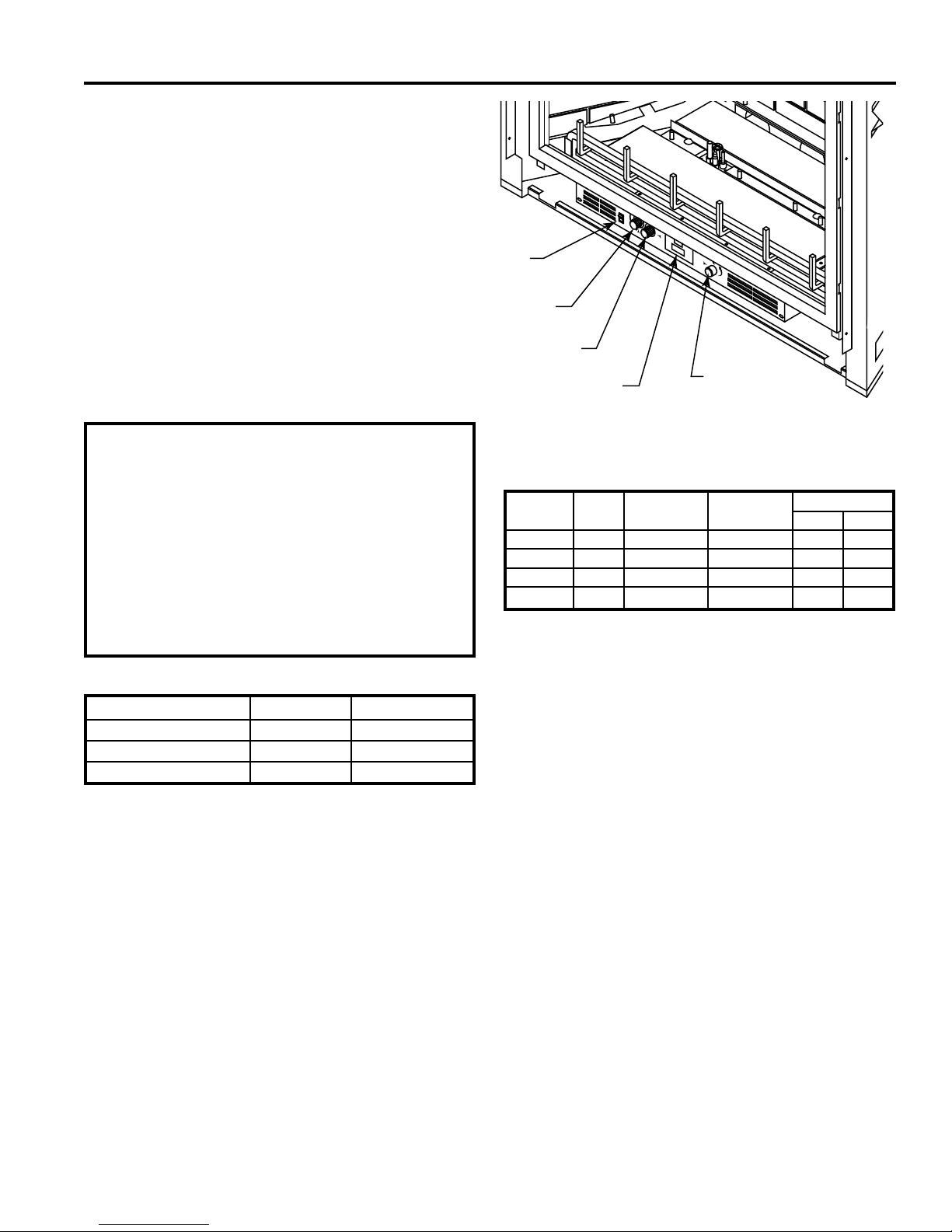
LX Series Direct Vent Gas Fireplace
On/Off/
RS Switch
Off/Pilot/On
Knob
Hi/Lo Knob
Optional Remote
Receiver
Figure 1 LXDV Fireplace Controls
OFF
Blower Control
GAS SPECIFICATIONS & ORIFICE SIZE
Max.Input Min. Input Orice Size
Model Fuel BTU/h BTU/h Front Rear
LX32NV Nat. 36,000 26,000 #46 #43
LX32PV LP 36,000 22,000 3/64" #55
LX36NV Nat. 44,000 30,000 #41 #38
LX36PV LP 44,000 32,000 #55 #53
FP2710
GAS PRESSURES
Natural Propane (LP)
Inlet Minimum 4.5” w.c. 11.0” w.c.
Inlet Maximum 10.5” w.c. 13.0” w.c.
Manifold Pressure 3.5” w.c. 10.0” w.c.
20306749
5
LX Series Direct Vent Gas Fireplace
LX36 Dims
235
33
3
4
40
1
2
43
1
2
5
12
1
24
3
45
3
4
1
2
23
1
2
1
2
12
5
2
3
4
35
5
5
1
1
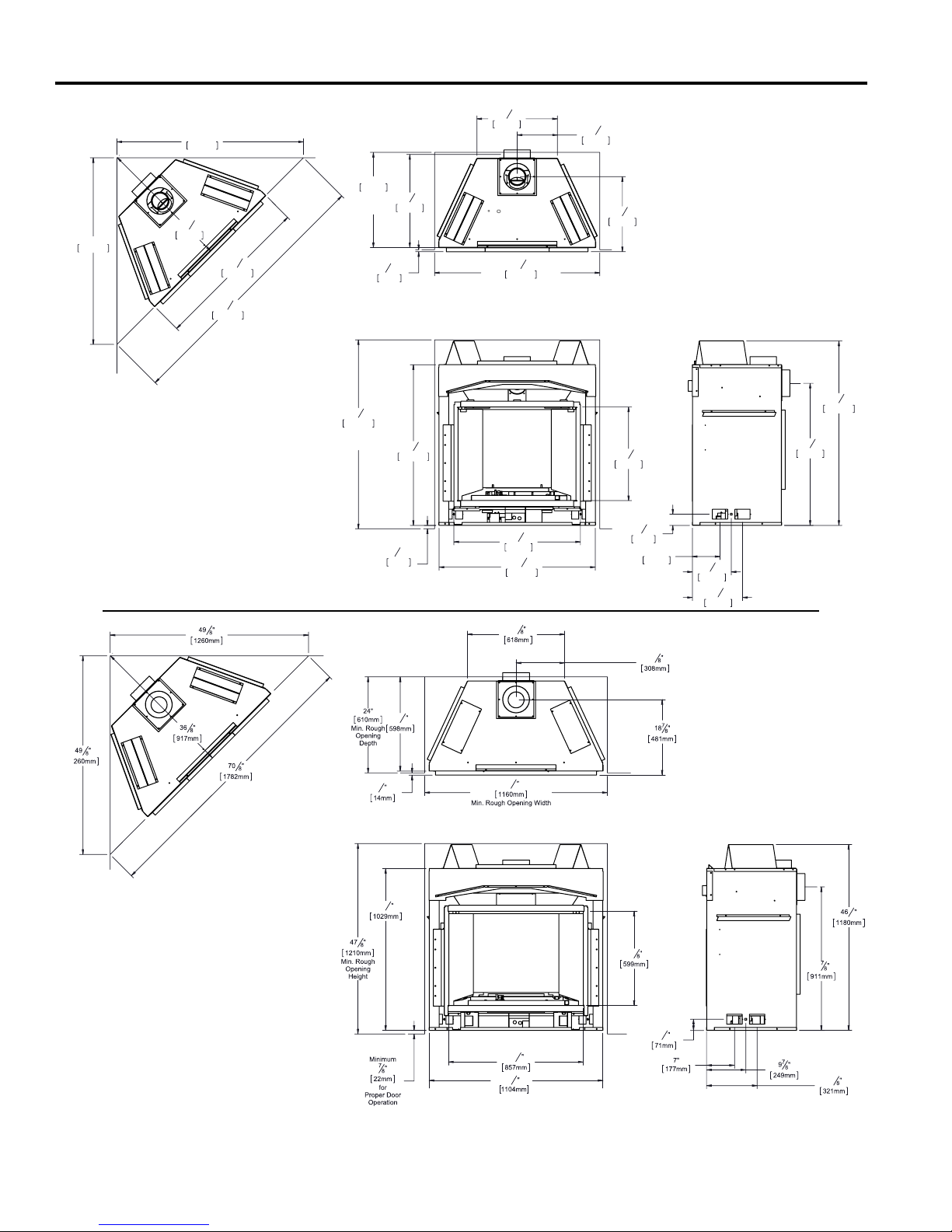
PRE-INSTALLATION INFORMATION
FIREPLACE and FRAMING DIMENSIONS
47"
1195mm
24"
610mm
Min. Rough
23
Opening
597mm
5
47
1210mm
Min. Rough
Opening
Height
8
Depth
"
1
"
2
13mm
40
Minimum
7
22mm
for Proper
Door
Operation
1029mm
"
8
1
"
33
4
47"
1195mm
845mm
66
39
1006mm
1690mm
5
"
8
1
"
2
Figure 2 LX32 Fireplace & Framing Dimensions
1
20
"
4
515mm
1
"
2
3
41
"
4
1059mm
Min. Rough opening Width
1
"
2
7
"
31
8
810mm
3
39
"
8
1000mm
10
258mm
1
"
8
7
18
"
8
480mm
1
"
46
2
1180mm
3
"
35
23
599mm
5
2
8
"
71mm
3
4
"
7"
177mm
7
"
9
8
249mm
5
"
12
8
321mm
910mm
4
Figure 3 LX36 Fireplace & Framing Dimensions
6
20306749
PRE-INSTALLATION INFORMATION
LX Series Direct Vent Gas Fireplace
BEFORE YOU START
Read this homeowner manual thoroughly and follow all
instructions carefully. Inspect all contents for shipping
damage and immediately inform your dealer if any damage
is found. Do not install any unit with damaged, incomplete,
or substitute parts. Check your packing list to verify that
all listed parts have been received. You should have the
following:
• Fireplace (Firebox and Burner System)
• Log Set
• Propane Conversion Kit
• Rock Wool
• Deector Shield (to be used with Duravent Horizontal
Termination – P/N 985)
ITEMS REQUIRED FOR INSTALLATION
Tools and Building Supplies:
• Phillips Screwdriver • Hammer
• Saw and/or saber saw • Level
• Measuring Tape • Pipe Wrench
• Electric Drill and Bits • Tee Joint
• Pliers • Square
• Framing Materials • Wall Finishing Materials
• Piping Complying with Local Codes
• Caulking Material (Noncombustible)
• Fireplace Surround Material (Noncombustible)
• Pipe Sealant Approved for use with Propane/LPG
(Resistant to Sulfur Compounds)
FIREPLACE FRAMING
Firebox framing can be built before or after the appliance
is set in place. Construct rebox framing following Figure
2 or 3. The framing headers may rest on the top of the
rebox standoffs.
The rebox may be installed directly on a combustible oor
or raised on a platform of an appropriate height. When
the rebox is installed directly on carpeting, tile, or other
combustible material, other than wood ooring, the rebox
shall be installed on a metal or wood panel extending the
full width and depth of the enclosure.
To access control door, build a platform to make the
bottom of appliance equal to or higher than top of nished
hearth extension, or elevate unit a minimum of 7/8" above
suboor.
Fireplace must be raised minimum 7/8" to
allow door to open.
NOTE
The 1" standoffs on back and sides and 6"
standoffs on top of replace are designed
to separate replace from framing. These
standoffs may contact framing but no
material may be placed between standoff
WARNING
and side of replace.
Do not fill spaces around firebox with
insulation or other materials. This could
cause a re.
20306749
WARNING
7
LX Series Direct Vent Gas Fireplace
FIREPLACE LOCATION
Plan for the installation of your appliance. This includes
determining where the unit is to be installed, the vent con-
guration to be used, framing and nishing details, and
whether any optional accessories (i.e. blower, wall switch,
or remote control) are desired. Consult your local building
code agency to ensure compliance with local codes, including permits and inspections.
The following factors should be taken into consideration:
• Clearance to side-wall, ceiling, woodwork, and windows.
Minimum clearances to combustibles must be main-
tained.
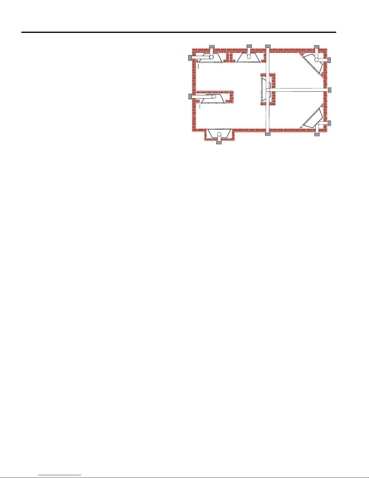
• This replace may be installed along a wall, across a
corner, or use an exterior chase. Refer to Figure 4 for
suggested locations.
• Location should be out of high trafc areas and away
from furniture and draperies due to heat from appliance.
• Never obstruct the front opening of the replace.
• Do not install in the vicinity where gasoline or other
ammable liquids may be stored.
• Vent pipe routing. See VENTING section found in this
manual for allowable venting congurations.
• These units can be installed in a bedroom. See National
Fuel Gas Code ANSI Z233.1/NFPA 54 — (current
edition), the Uniform Mechanical Code — (current edi-
tion), and Local Building Codes for specic installation
requirements.
PRE-INSTALLATION INFORMATION
E
Y
D
Y
F
A Flat on Wall
B Cross Corner
C Island**
D Room Divider*
E Flat on Wall Corner*
F Chase Installation
Y 9" Minimum
** Island (C) and room divider (D) installation is possible as long
as the horizontal portion of vent system (X) does not exceed
20'. See Installing Horizontal Termination Conguration on
Pages 20 and 21.
* When you install your replace in (D) room divider or (E)
at on wall corner positions (Y), a minimum of 6" clearance
must be maintained from perpendicular wall and front of
replace.
A
C
B
X
B
Figure 4 Locating Gas Fireplace
8
20306749
PRE-INSTALLATION INFORMATION
LX Series Direct Vent Gas Fireplace
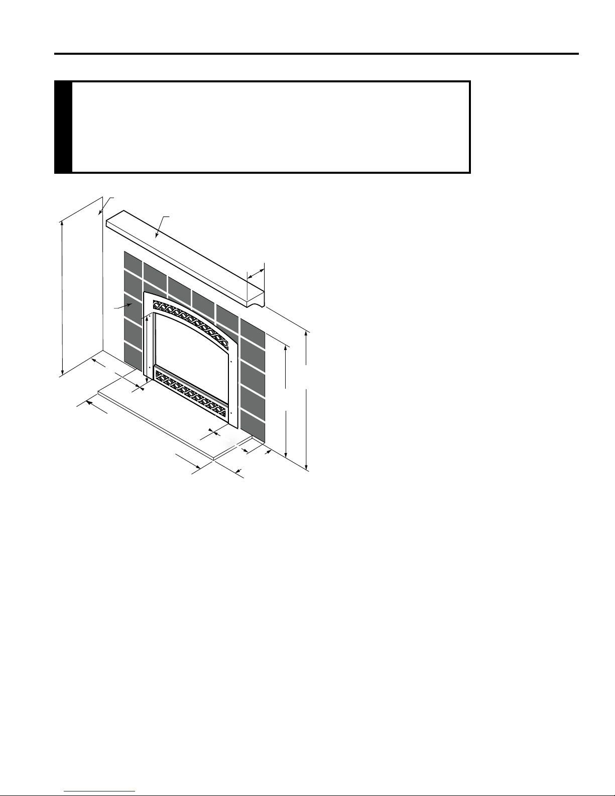
CLEARANCES TO COMBUSTIBLES
Follow these instructions carefully to ensure safe installation. Failure to
follow instructions exactly can create a re hazard.
The appliance cannot be installed on a carpet, tile or other combustible
material other than wood ooring. If installed on carpet or vinyl ooring, the
appliance shall be installed on a metal, wood or noncombustible material
WARNING
panel extending full width and depth of the appliance.
Ceiling
Noncombustible Facing
9” (229 mm)
Minimum
Figure 5 Clearances to Combustible
Materials
Side Wall
LX32 - 30” (762 mm)
LX36 - 34” (864 mm)
LX32 - 39” (991 mm)
LX36 - 43” (1092 mm)
Combustible
Mantel
(152 mm)
12” (305 mm)
Max. Depth
6”
12” (305 mm)
Minimum
MANTEL CLEARANCES
NOTE: The combustible area above the facing must
not protrude more than 3/4" from the facing. If it does,
it is considered a mantel and must meet the mantel
requirements listed in this manual.
HEARTH REQUIREMENTS
The replace must be installed on a non-combustible hearth
extending a minimum of 12" from the replace opening
(local codes may require a larger hearth). The hearth must
also extend to both sides of the face (see the table above
for the exact width of the face).
46³⁄₄”
(1187 mm)
44³⁄₄”
(1137 mm)
FP2711
20306749
9
LX Series Direct Vent Gas Fireplace
PRE-INSTALLATION INFORMATION
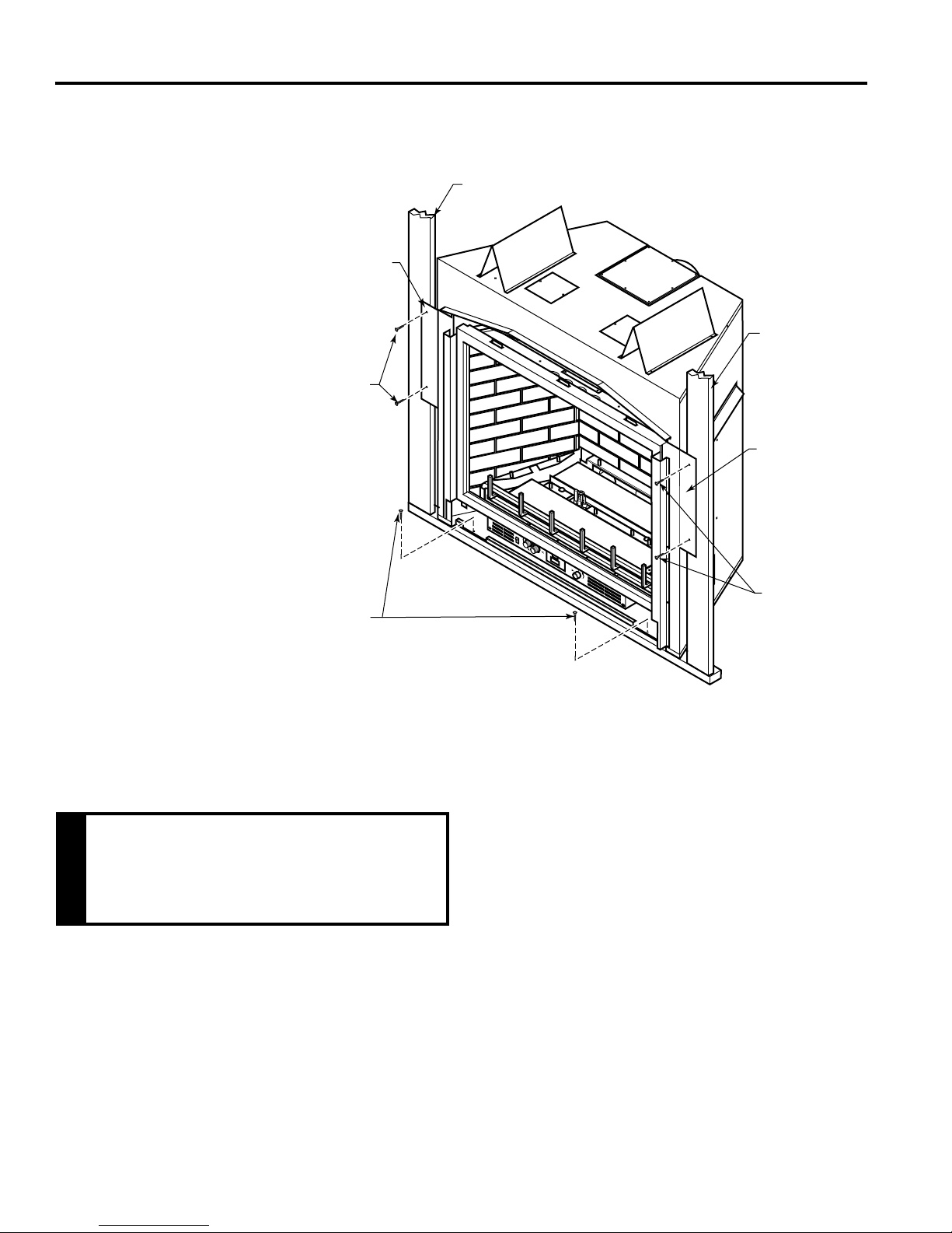
The replace must be secured to the oor and/or to framing studs as shown in Figure 6. Use two
(2) wood screws or masonry/ concrete screws to secure replace to the oor. Use four (4) screws
to attach replace to framing. The side brackets are adjustable from 1/2" to 5/8" to accommodate
different thickness of noncombustible material.
Framing
Adjustable
Bracket
Screws
Framing
Adjustable
Bracket
OFF
Screws
Figure 6 Securing Fireplace to Floor and Framing Studs
FP2712
NOTE: Do not allow combustibles (drywall) to touch top and side edges of black-painted metal
face of replace. Only use noncombustibles. A 4" wide or more cement board may touch the
top and side edges of black-painted metal face of replace.
Do not allow any combustible to overlap the black-painted face of replace.
Never obstruct or modify the air inlet or
outlet grills (louvers). This may create a
re hazard.
WARNING
FINISHING MATERIAL
NOTE: Any remote wiring (i.e. remote control, wall switch, and optional fan) must be done prior to
nal nishing to avoid costly reconstruction.
Only noncombustible materials (i.e. brick, tile, slate, steel, or other materials with a UL re rating
of Zero) may be used to cover the black surface of the appliance. A 300°F minimum adhesive may
be used to attach facing materials to the black surface. If joints between the nished wall and the
replace surround are sealed, a 300°F minimum sealant material (General Electric RTV103 or
equivalent) must be used.
Screws
10
20306749
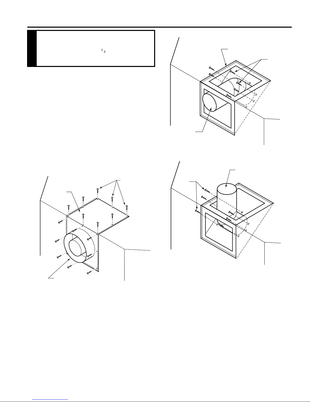
VENTING INSTALLATION
After conversion to top vent conguration
the 4" (102 mm) flue pipe should be
concentric within the 65⁄8" (175 mm) outer
collar (within 1/4").
WARNING
OPTIONAL TOP VENT APPLICATION
The appliance is shipped as a rear vent unit. If the installa-
tion layout requires the unit to be a top vent conguration
the appliance can be converted by the following steps.
When removing and retting the plates and adapter be
sure the associated gaskets are undamaged and retted
as required.
1. Remove the eight (8) screws securing the ue pipe
adapter to the replace body. Figure 7
2. Set the ue pipe adapter aside, complete with the
gasket. Do not damage the gaskets as the adapter and
gasket must be retted.
3. Remove the eight (8) screws securing the ue pipe cover
to the top of the intake box and remove the cover and
gasket. Figure 7
LX Series Direct Vent Gas Fireplace
Flue Cover
Screws
Flue Pipe
FP1992
Figure 8 Remove Flue Pipe
Flue Pipe
Screws
Flue Pipe
Cover
FP1991
Flue Pipe
Adapter
Figure 7 Remove 16 Screws from Flue Pipe
Adapter and Flue Pipe Cover
4. Remove eight (8) screws securing the ue pipe to the
back of the intake box and remove the pipe and gasket.
Figure 8
5. Replace ue pipe to top of rebox. Ensure the gasket is
in place and undamaged. Secure with eight (8) screws.
Figure 9
6. Place the ue pipe cover and gasket removed in step
3 over the ue opening in bottom of the intake box.
Screws
Figure 9 Attach Flue Pipe to Top
Vent Congurations
FP1993
7. Ret the ue pipe adapter and gasket to the top of replace. Secure the adapter with eight (8) screws removed
in Step 1.
20306749
11
LX Series Direct Vent Gas Fireplace
VENTING INSTALLATION
Read all instructions completely and
thoroughly before attempting installation.
Failure to do so could result in serious
injury, property damage or loss of life.
Operation of improperly installed and
maintained venting system could result in
WARNING
serious injury, property damage or loss of
life.
Failure to follow these instructions will
void the warranty.
NOTICE
INSTALLATION PRECAUTIONS
Consult local building codes before beginning
the installation. The installer must make
sure to select the proper vent system for
installation. Before installing vent kit, the
installer must read this replace manual and
vent kit instructions.
Only a qualied installer/service person should
install venting system. The installer must follow
these safety rules:
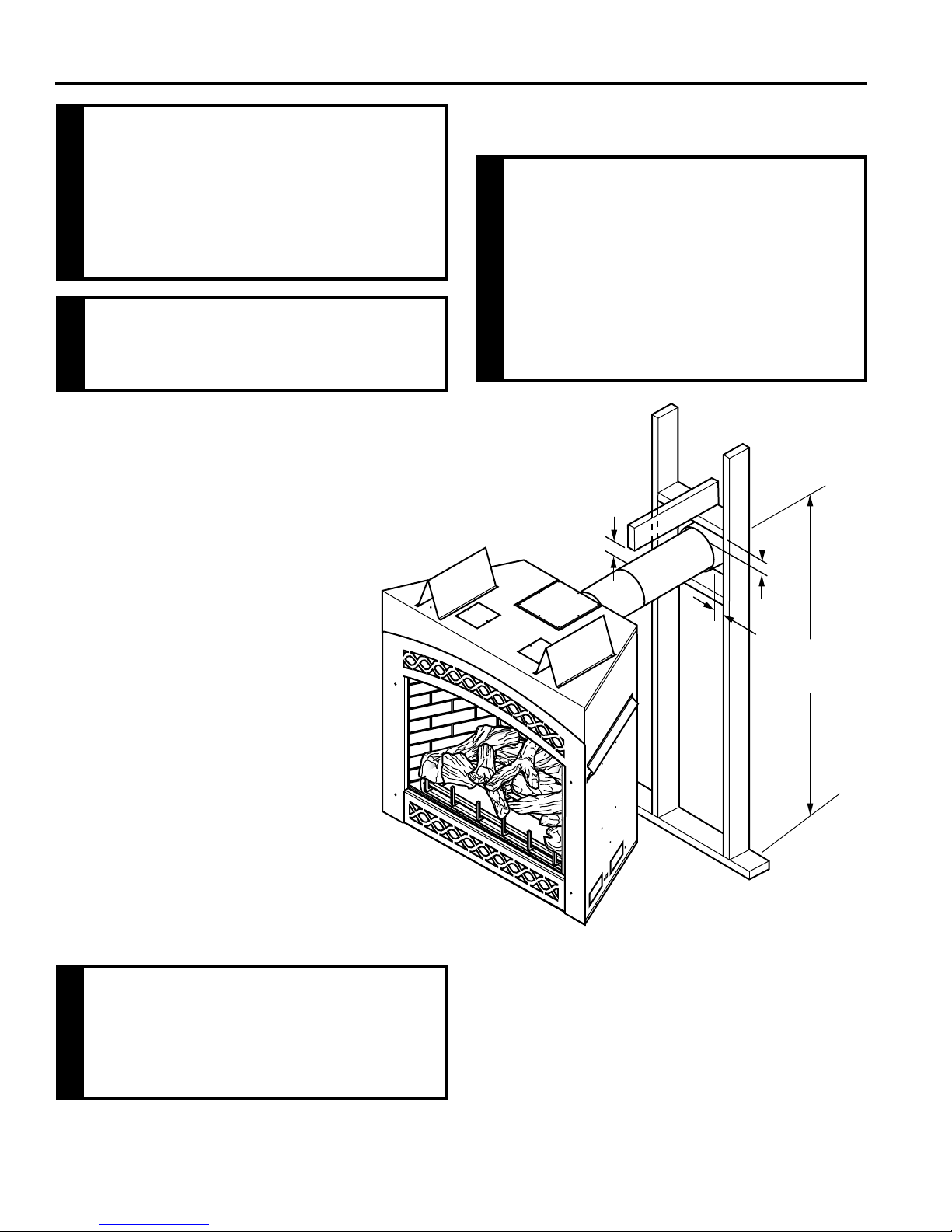
COMBUSTIBLE CLEARANCES FOR VENT
PIPE
Horizontal sections of this vent system
require a minimum of 3" clearances to
combustibles at the top of the ue and 1"
clearance at the sides and bottom until
the flue penetrates the outside wall. A
minimum 1" clearance all around the ue is
acceptable at this point of penetration.
WARNING
Vertical sections of this vent system require
a minimum of 1" clearance to combustibles
on all sides of the pipe.
1"
*3"
**1"
• Wear gloves and safety glasses for protec-
tion.
• Use extreme caution when using ladders
or when on rooftops.
• Be aware of electrical wiring locations in
walls and ceilings.
The following actions will void the warranty on
your venting system:
• Installation of any damaged venting com-
ponent.
• Unauthorized modication of the venting
system.
• Installation of any component part not
manufactured or approved by Vermont
Castings Group.
• Installation other than permitted by these
instructions.
This replace must be vented to the outside.
The venting system must NEVER be attached
to a chimney serving a separate solid fuel
burning appliance. Each gas appliance must
use a separate vent system. Do not use
WARNING
common vent systems.
**1"
35⁷⁄₈”
(911 mm)
FP2713
Figure 10 Combustible Clearances for Vent Pipe
* A minimum of 3" clearance to the top is required along
horizontal length until ue pipe penetrates outside wall.
** A minimum 1" clearance to combustibles permitted all
around ue at outside wall
12
20306749
VENTING INSTALLATION
INSTALLATION PLANNING
There are two basic types of direct-vent installation:
• Horizontal Termination
• Vertical Termination
It is important to select the proper length of vent pipe for
the type of termination you choose. It is also important to
note the wall thickness.
FOR HORIZONTAL TERMINATION
Select the amount of vertical rise desired. All horizontal
run of venting must have minimum 1/4" rise for every 12"
of run towards the termination.
You may use up to three 90° elbows in this vent conguration. Refer to Horizontal (Through the Wall) Termination
Congurations on Page 18.
FOR VERTICAL TERMINATION
Measure the distance from the replace oor to the ceiling. Add the ceiling thickness, the vertical rise in an attic
or second story, and allow for sufcient vent height above
the roof line.
NOTE: You may use two 45° elbows in place of a 90° elbow.
You must follow rise to run ratios when using 45° elbows.
The appliance is approved for use with three 90° elbows
maximum or a combination of 90° and 45° elbows up to
a maximum of 270°.
For two-story applications, restops are required at each
oor level. If an offset is needed in the attic, additional pipe
and elbows will be required.
You may use a chase with a vent termination with exposed
pipe on the exterior of the house. See Installing Vent
System in a Chase below. If pipe is enclosed in chase, it
is not exposed.
It is very important that the venting system maintain its bal-
ance between the combustion air intake and the ue gas
exhaust. Certain limitations apply to vent congurations
and must be strictly followed.
LX Series Direct Vent Gas Fireplace
Never run the vent pipe level or downward.
This may cause excessive temperatures
which could cause a re.
WARNING
INSTALLING A VENT SYSTEM IN AN
OUTSIDE CHASE
A chase is a vertical boxlike structure built to enclose
venting that runs along the outside of a building. A chase
is required for such venting.
When installing in a chase, you should
insulate the chase as you would the outside
walls of your home. This is especially
important in cold climates. Insulation
should be considered a combustible
NOTICE
material. Maintain proper clearances to all
combustible materials.
Always maintain minimum clearances
around vent systems. The minimum
clearances to combustibles for horizontal
vent pipe are 3" at the top and 1" at the
sides and bottom of the vent system until
the pipe penetrates the nearest vertical wall.
A 1" minimum clearance all around the pipe
must be maintained. Do not pack the open
WARNING
air spaces with insulation or other materials.
This could cause high temperatures and
may present a re hazard.
Treatment of restops and construction of
the chase may vary from building type to
building type. These instructions are not
substitutes for the requirements of local
NOTICE
building codes. You must follow all local
building codes.
20306749
13
LX Series Direct Vent Gas Fireplace
V
X
X
X
D
E
B
B
B
C
B
M
B
A
J
K
F
L
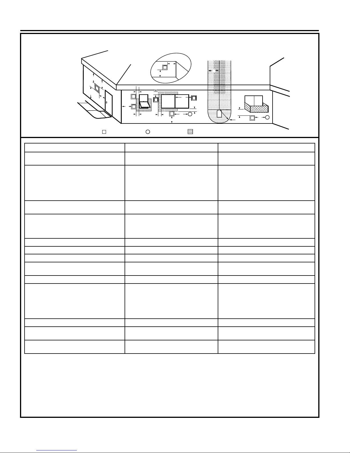
VENT TERMINATION AIR SUPPLY INLET
AREA WHERE TERMINAL IS NOT PERMITTED
H
I
Fixed
Closed
Operable
Operable
Fixed
Closed
B
INSIDE
CORNER DETAIL
A
G
CFM145a
V
V
V
V
V
V
V
V
TERMINATION LOCATION
Termination Locations
VENTING INSTALLATION
A = Clearance above grade, veranda, porch,
CANADIAN INSTALLATIONS
1
12" (30cm) 12" (30cm)
US INSTALLATIONS
2
deck or balcony
B = Clearance to window or door that may be
opened
C = Clearance to permanently closed window 12" (305mm) recommended to prevent
D = Vertical clearance to ventilated soft locat-
6" (15cm) for appliances <10,000 BTU/h
(3kW)
12" (30cm) for appliances >10,000 BTU/h
(3kW) and <100,000 BTU/h (30kW)
36" (91cm) for appliances >100,000 BTU/h
(30kW)
6" (15cm) for appliances <10,000 BTU/h
(3kW)
9" (23cm) for appliances >10,000 BTU/h
(3kW) and <50,000 BTU/h (15kW)
12" (30cm) for appliances >50,000 BTU/h
(15kW)
12" (305mm) recommended to prevent win-
window condensation
dow condensation
18" (458mm) 18" (458mm)
ed above the terminal within a horizontal
distance of 2' (610 mm) from the center
line of the terminal
E = Clearance to unventilated soft 12" (305mm) 12" (305mm)
F = Clearance to outside corner see next page see next page
G = Clearance to inside corner see next page see next page
H = Clearance to each inside of center line
extended above meter/regulator assembly
3' (91cm) within a height of 15' (5m) above
the meter/regulator assembly
3' (91cm) within a height of 15' (5m) above
the meter/regulator assembly
I = Clearance to service regulator vent outlet 3' (91cm) 3' (91cm)
J = Clearance to non-mechanical air supply
inlet to building or the combustion air inlet
to any other appliance
6" (15cm) for appliances <10,000 BTU/h
(3kW)
12" (30cm) for appliances >10,000 BTU/h
(3kW) and <100,000 BTU/h (30kW)
36" (91cm) for appliances >100,000 BTU/h
(30kW)
6" (15cm) for appliances <10,000 BTU/h
(3kW)
9" (23cm) for appliances >10,000 BTU/h
(3kW) and <50,000 BTU/h (15kW)
12" (30cm) for appliances >50,000 BTU/h
(15kW)
K = Clearance to mechanical air supply inlet 6' (1.83m) 3' (91cm) above if within 10' (3m) horizontally
L = Clearance above paved sidewalk or
7' (2.13m)
†
7' (2.13m)
†
paved driveway located on public property
M = Clearance under veranda, porch, deck or
12" (30cm)
‡
12" (30cm)
‡
balcony
1 In accordance with the current CSA-B149 Installation Codes
2 In accordance with the current ANSI Z223.1/NFPA 54 National Fuel
Gas Codes
† A vent shall not terminate directly above a sidewalk or paved
driveway which is located between two single family dwellings and
serves both dwellings
‡ Only permitted if veranda, porch, deck or balcony is fully open on a
minimum 2 sides beneath the oor.
14
NOTE: 1. Local codes or regulations may require different
2. The special venting system used on Direct Vent
3. Vermont Castings Group assumes no responsibility for
clearances.
Fireplaces are certied as part of the appliance, with
clearances tested and approved by the listing agency.
the improper performance of the appliance when the venting
system does not meet these requirements.
20306749
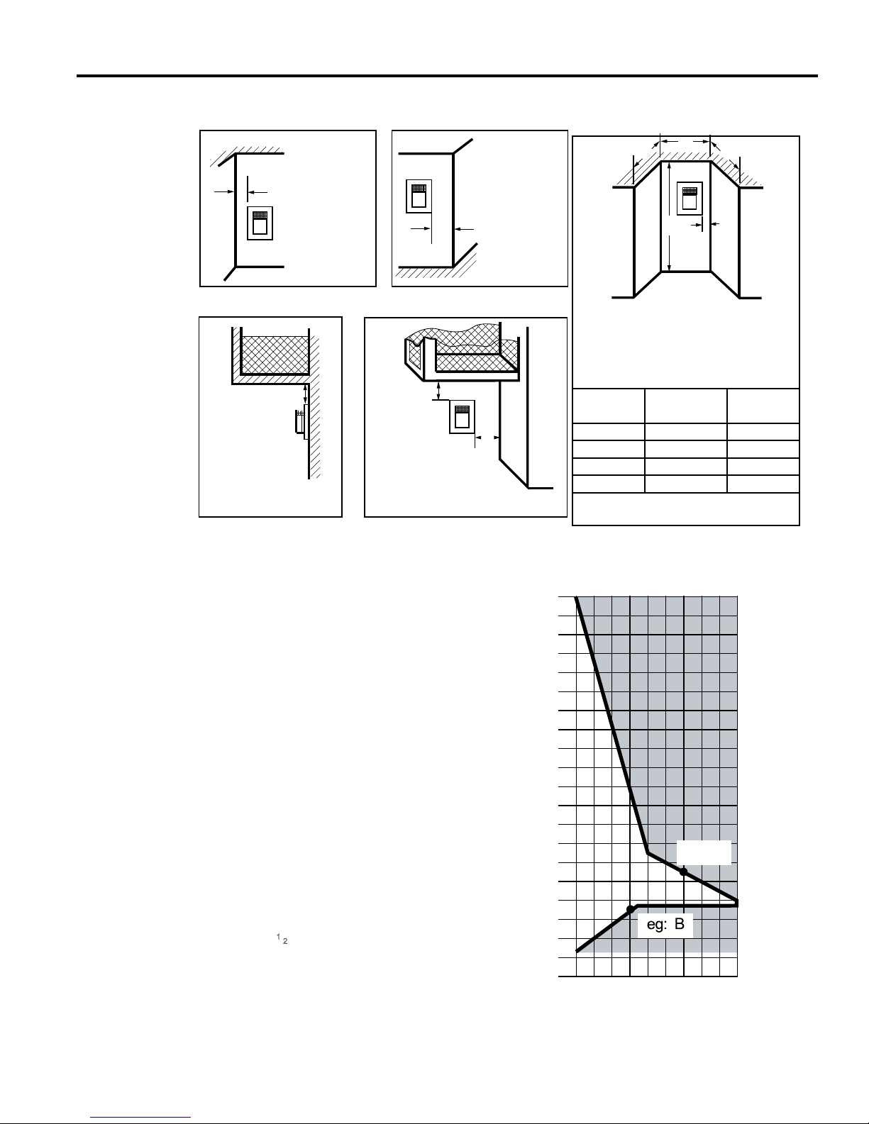
VENTING INSTALLATION
Termination Clearances
Termination clearances for buildings with combustible and noncombustible exteriors.
Inside Corner
G
V
G =
Combustible
6" (152 mm)
Noncombustible
2" (51 mm)
Outside Corner
V
F
LX Series Direct Vent Gas Fireplace
F =
Combustible
6" (152 mm)
Noncombustible
2" (51 mm)
Alcove Applications*
D
C
V
O
C
E
Balcony -
with no side wall
Figure 12 Allowable
Venting
M
V
M =
Combustible &
Noncombustible
12" (305 mm)
*NOTE: Termination in an alcove space (spaces open only on one side and with an overhang) is permitted with the dimensions specied for vinyl or
non-vinyl siding and softs. 1. There must be a 3’ (914 mm) minimum between termination caps. 2. All mechanical air intakes within 10’ (1 m) of a
termination cap must be a minimum of 3’ (914 mm) below the termination cap. 3. All gravity air intakes within 3’ (914 mm) of a termination cap must
be a minimum of 1’ (305 mm) below the termination cap.
Balcony -
with perpendicular side wall
M
V
P
Combustible &
Noncombustible
M = 12" (305 mm)
P = 6” (152 mm)
E = Min. 2” (51 mm) for
non-vinyl sidewalls
Min. 12” (305 mm) for
vinyl sidewalls
O = 8’ (2.4 m) Min.
No.
of Caps DMin. CMax.
1 3’ (914 mm) 2 x DActual
2 6’ (1.8 m) 1 x DActual
3 9’ (2.7 m) 2/3 x DActual
4 12’ (3.7 m) 1/2 x DActual
DMin. = # of Termination caps x 3
584-15
CMax. = (2 / # termination caps) x DActual
40
HOW TO USE THE VENT GRAPH
The Vent Graph should be read in conjunction with the
following vent installation instructions to determine the
relationship between the vertical and horizontal dimensions
of the vent system.
1. Determine the height of the center of the horizontal vent
pipe exiting through the outer wall. Using this dimension
on the Sidewall Vent Graph, locate the point intersecting
with the slanted graph line.
2. From the point of this intersection, draw a vertical line
to the bottom of the graph.
3. Select the indicated dimension, and position the replace in accordance with same.
Example: If the vertical dimension from the oor of the
replace is 11' (3.4 m) the horizontal run to the face of
the outer wall must not exceed 14' (4.3 m).
Example: If the vertical dimension from the oor of the
unit is 7’ (2.14 m), the horizontal run to the face of the
outer wall must not exceed 8
Sidewall Vent Graph showing the relationship between
vertical and horizontal dimensions for a Direct Vent ue
system.
1
⁄2' (2.6 m).
Figure 13 Rear Wall Venting Graph
Horizontal Dimension From the Outside Face of the Wall
38
36
34
Dimensions in
Feet
32
30
28
26
24
22
20
18
16
Horizontal Vent Pipe
14
12
eg: A
10
8
6
4
Vertical Dimension From the Floor of Unit to the Center of the
2
2 4 6 8 10 12 14 16 18 20
to the Back of the Fireplace
20306749
15
 Loading...