

Page 1
LHEACNSS Contour
Trim Kit
Installation Instructions
Kit: KT1B80
for Models LHEC30,
LHEC20, LHER20
Assembly
Determine which model fireplace insert you have. This
will be important when adjusting the height and width of
the surround.
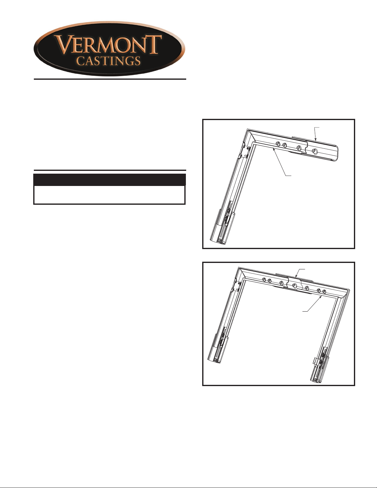
1. Place the key (30001981) on your work surface with
the threaded holes facing up.
2. Place the column right assembly (30002073) onto
the key. (Fig. 1)
3. Place the column left assembly (30002074) onto the
key. (Fig. 2)
Key
Caution
Always place castings on a flat protected work surface, such as a towel, blanket or carpet.
These instructions cover the assembly of the KT1B80
Trim Kit and installation to the LHEC30, LHEC20 and
LHER20 fireplace inserts.
Carefully unpack and inspect all components from the
shipping box. Report any missing or damaged parts to
your dealer immediately. Install trim kit after all other
fireplace installation work has been completed, thoroughly checked and tested for proper operation, leaks
and installation requirements.
Tools required: Tape measure
Trim kit parts Part #
Column Right Assembly 30002073
(1) Column, right 30001978
(1) Boot, right 30001982
(1) Slider Clip, right 30002050
(1) Bracket, On/Off Switch 10005035
(2) 1/4-20 Round Head Screw 1200894
(2) 1/4-20 Wing Screw 1201621
(3) 1/4 Flat Washer 1202474
Column Left Assembly 30002074
(1) Column, left 30001979
(1) Boot, left 30001983
(1) Slider Clip, left 30002049
(1) 1/4-20 Round Head Screw 1200894
(2) 1/4-20 Wing Screw 1201621
(3) 1/4 Flat Washer 1202474
Key 30001981
Upper Mounting Bracket 30002053
Upper Mounting Bracket R 30002054
Hardware Bag: 30001988
(5) 1/4-20 Wing Screw 1201621
(5) 1/4 Flat Washer 1202474
Instruction Sheet 30001987
Column Right Assembly
KT424
Fig. 1 Place column right assembly onto key.
Key
Column Left
Assembly
KT425
Fig. 2 Place column left assembly onto key.
4. Install the upper mounting bracket. Use the upper
mounting bracket marked R (30002054) for the
LHER20. Use the unmarked upper mounting bracket
(30002053) for LHEC30 and LHEC20. (Fig. 3)
30001987 8/08 Rev. 4
Page 2
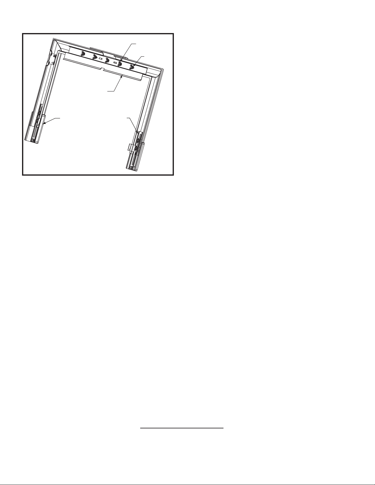
Upper Mounting
Bracket
Boot
Fig. 3 Install upper mounting bracket.
Slider Clip
1/4-20 Wing
Screw
1/4 Flat
Washer
KT426
5. Fasten the upper mounting bracket to the key with
a 1/4-20 wing screw and 1/4 flat washer finger tight.
(Fig. 3)
6. Fasten the upper mounting bracket to both column
assemblies using (2) 1/4-20 wing screws and (2)
1/4 flat washers per side finger tight. The distance
between the insides of the columns should measure:
LHEC30 = 29
³⁄₁₆” (741mm)
LHEC20 & LHER20 = 25⁵⁄₈” (651mm)
7. Adjust the column/boot length (measure from the
bottom side of the key to the bottom of the boot).
LHEC30 = 22
LHEC20 = 18
LHER20 = 17
¹⁄₄” (565mm)
¹⁄₄” (464mm)
⁵⁄₈” (448mm)
8. Lift the surround up and parallel to the fireplace
front. Press the Fan ON/OFF switch into the switch
bracket. It will snap into place. (Refer to Homeowner’s manual for additional switch installation instructions) Move the surround towards the fireplace about
an inch above the hearth. As you lower the surround
onto the fireplace, the side clips and top bracket will
engage mating clips. If height and width adjustments
are required, lift the surround up and out. Make the
adjustments. Regardless if adjustments were made
or not, tighten all wing screws fasteners and return
the surround to the fireplace.
MHSC
149 Cleveland Drive • Paris, Kentucky 40361
www.mhsc.com
 Loading...