

Page 1
Cast Iron Surrounds
4
4
2
5
8
8
1
8
6
79
9
8
7
3
Installation Instructions
Models LHE20CSLB,
LHE30CSLB
For use on LHE20 and
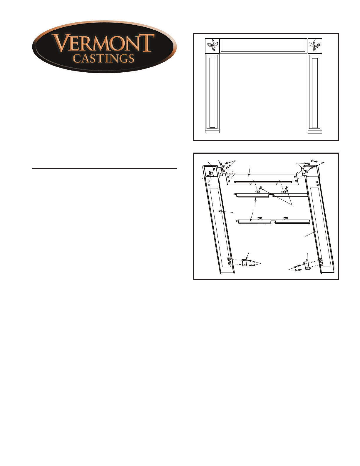
Fig. 1 Front view of surround assembly.
KT393
LHE30 Fireplace Inserts
Please read these instructions before beginning the
installation.
These instructions cover the assembly of Models
LHE20CSLB and LHE30CSLB cast iron surrounds for
use on the LHE20 and LHE30 model fireplace inserts.
Check Contents of Shipping Carton
Compare contents of carton in Figure 2 with actual
parts received. If any parts are missing, or damaged,
contact your dealer before starting installation.
Surround Parts:
1. Right column
2. Mantel
3. Left column
4. Lower bracket (2)
5. Upper bracket (2)
6. Switch housing (1)
7. Hex head bolt, 1/4” -20 x 3/8” (4)
8. Phillips pan head bolt, 1/4” x 3/8” (7)
9. Washers, 7/8” (4)
General Information
The assembly includes three (3) cast iron surround
panels, four (4) sheet steel brackets, a switch housing
and hardware. The switch housing is for use with ʻCʼ
series fireboxes. It can be installed on either side of the
surround.
Install the Model LHECSLB surround after all other
installation work has been completed, thoroughly
checked, and tested for proper operation, leaks and
installation requirements.
KT394
Fig. 2 Back view of surround assembly.
Tools required:
Phillips screwdriver
7/16” wrench
Assembling the Surround
Lay out the parts, face down, on a flat padded surface.
(Fig. 2)
1. Align the holes in the top flanges of the left and right
columns with the drilled and tapped bosses onto the
left and right ends of the mantel.
2. Attach the mantel to the columns with four (4) 1/4”20 hex bolts and washers.
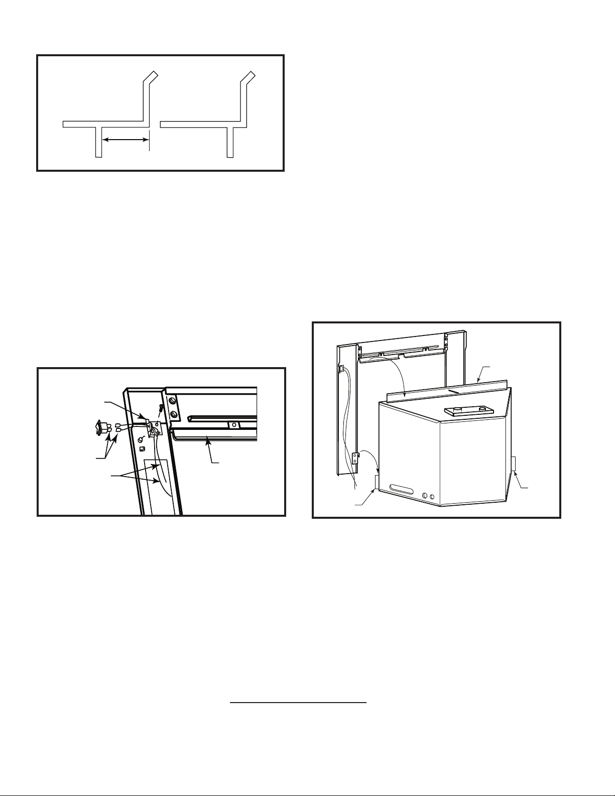
3. Only one upper bracket is used per surround. Determine which bracket is correct for the insert and
discard the other. (Fig. 3) Attach the upper bracket
to the mantel with two (2) phillips pan head bolts 3/8”
long. (Fig. 2)
30001946 8/08 Rev. 6
Page 2
Attaching the Surround
LHER20
LHER30
Deeper Set
Back
Fig. 3 Determine which bracket is correct for the installation.
LHEC20
LHEC30
KT398
4. Attach the two (2) lower brackets to the bottoms of
the columns with two (2) 3/8” phillips pan head bolts
each. (Fig. 2) NOTE: When positioning the right
column lower bracket, make sure one of the hooked
flanges is in the upper right hand corner and facing
towards you. The other hooked flange will be in the
opposite lower corner and facing away from you.
(Fig. 2)
The left column lower bracket is the opposite.
5. For ʻCʼ series units, choose which side of the sur-
round should have the ON/OFF switch, and attach
the switch housing to the back of that column with
one (1) 1/4-20 x 3/8” phillips pan head screw. (Fig. 4)
1. For ʻCʼ series units, attach the switch wires to
the valve. The wires attach to the ʻTH/TPʼ and the
ʻTHʼ terminals (the top and bottom terminals) on
the valve. Bring the wires to the side of the firebox.
If the switch housing is on the left side of the surround, bring the wires to the left side of the firebox.
Bring the wires up through the bottom of the switch
housing, and out through the side. (Fig. 4) Attach the
wires to the switch by pressing the wire connectors
onto the prongs of the switch. Press-fit the switch
into the housing. (Fig. 4)
2. Position surround in front of fireplace insert and,
with the help of an assistant, gently lift the surround
up and over the top flange and right and left side
flanges. Secure surround by applying downward
pressure until the lower brackets have engaged onto
the left and right side flanges. (Fig. 5)
3. This completes the assembly.
Lift surround up and
over top flange. Apply
downward pressure.
Top Flange
Switch
Housing
Switch
Connectors
Switch Wires
Fig. 4 (ʻCʼ Series units only) Attach the switch housing and
the switch. The housing can be attached to either column.
Upper Bracket
KT395
Right
Side
Flange
Fig. 5 Attach the cast surround to the fireplace insert.
Left
Side
Flange
KT396
MHSC
149 Cleveland Drive • Paris, Kentucky 40361
www.mhsc.com
 Loading...