

Page 1
Thermostatic Blower
Installation Instructions
Model: BLOTDL
Before You Start
This instruction sheet is ONLY for models listed below. Carefully inspect the contents for shipping damage. If any parts
are missing or damaged, immediately inform the dealer from whom you purchased the part.
Models: LSTF36, LPF36, LRF36, LLF36, 36STFL, 36PFL, 36RFL, 36LFL, (ST, CL, CR, PF)LDV
Kit Contents:
(1) Blower Assembly (4) Screws #14 x 3/4 (2) Screws #8 x 1/2 (1) Power Cord
(1) Speed Control (1) Speed Control Mounting Bracket (2) Wire Ties
(1) Gasket (2) High Temperature Wire (4) Rubber Grommets
(1) Thermostatic Sensor (Large screw-in style) (1) Thermostatic Sensor (Small snap-in style)
Tools Required:
Phillips screwdriver, Small jeweler’s style screwdriver
Before installing the blower, turn off the replace
and allow to cool. Only a qualied service person
should service and repair the replace. A qualied
service person should connect and disconnect the
replace to gas supply. Follow all local codes.
WARNING
Electrical Grounding Instructions:
This appliance is equipped with a three-prong
(grounding) plug for your protection against shock
hazard and should be plugged directly into a properly grounded three prong receptacle.
WARNING
Electrical connections should only be performed
by a qualied licensed electrician. Main power
supply must be turned off before connecting fans
to the main electrical power supply or performing
service.
CAUTION
IMPORTANT: Always check local building codes. This
installation must comply with local regulations as well
as the National Electric Code.
Installation Instructions
Wiring
1. Before installing the blower, wire the receptacle into an electrical circuit. This should be done
before framing the replace. Wire with minimum 60° C wire in accordance with prevailing
codes.
2. Remove the external junction box cover by removing the screw
from the left side of the outside rebox wall. Junction box was
installed at the factory.
3. The junction box cover has a factory installed “romex” style strain
relief connector. After connecting the wires, route the wire leads
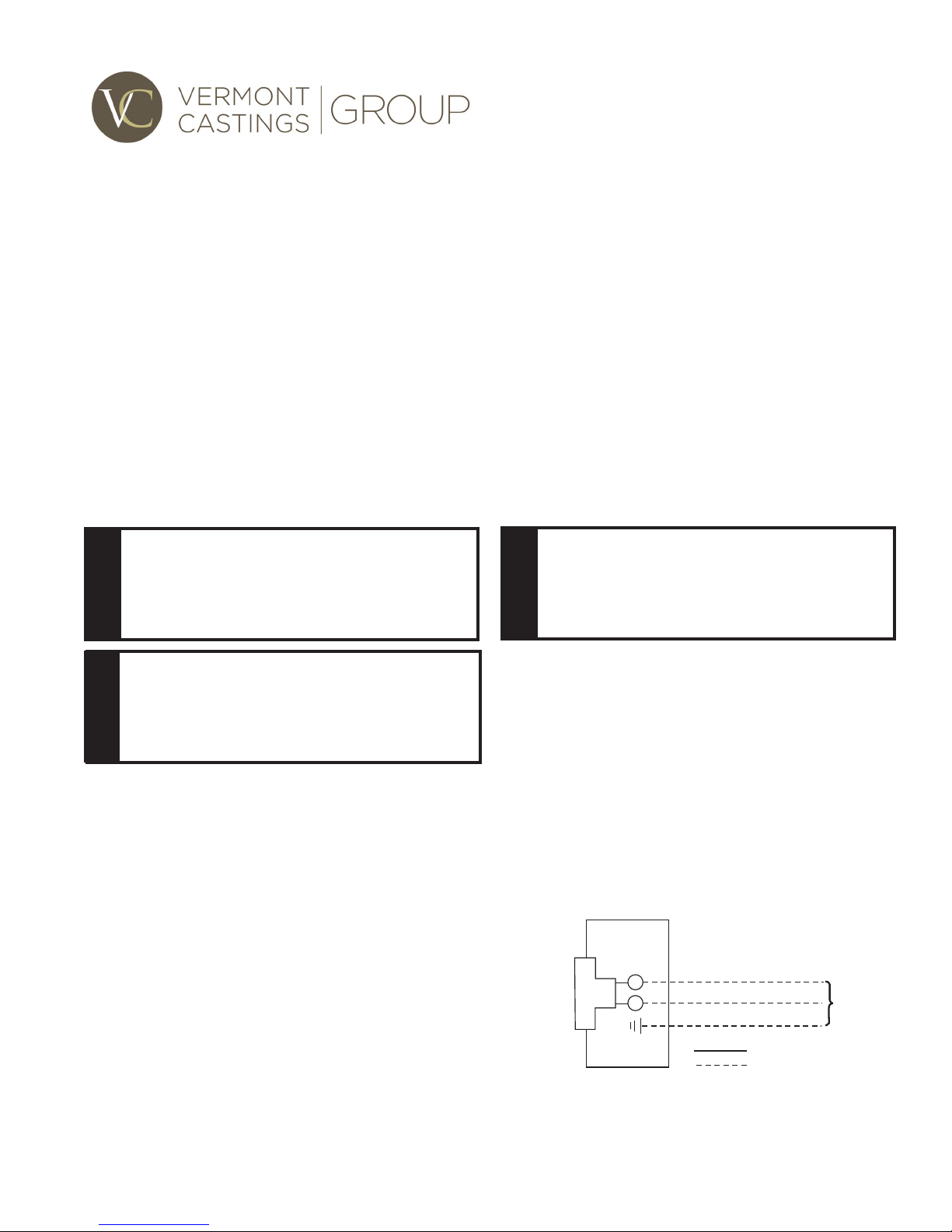
through this connector. Refer to the wiring diagram in Figure 1.
Junction Box
Figure 1
Junction Box Wiring Diagram
120V AC
60Hz
Factory Supplied
Not Supplied
79D0009 1/13 Rev. 3
Page 2
Installation Instructions - (LF,FL)
NOTE: The blower can be installed through the end access panel
at time of replace installation before framing.
1. Disconnect gas line and remove burner and logs.
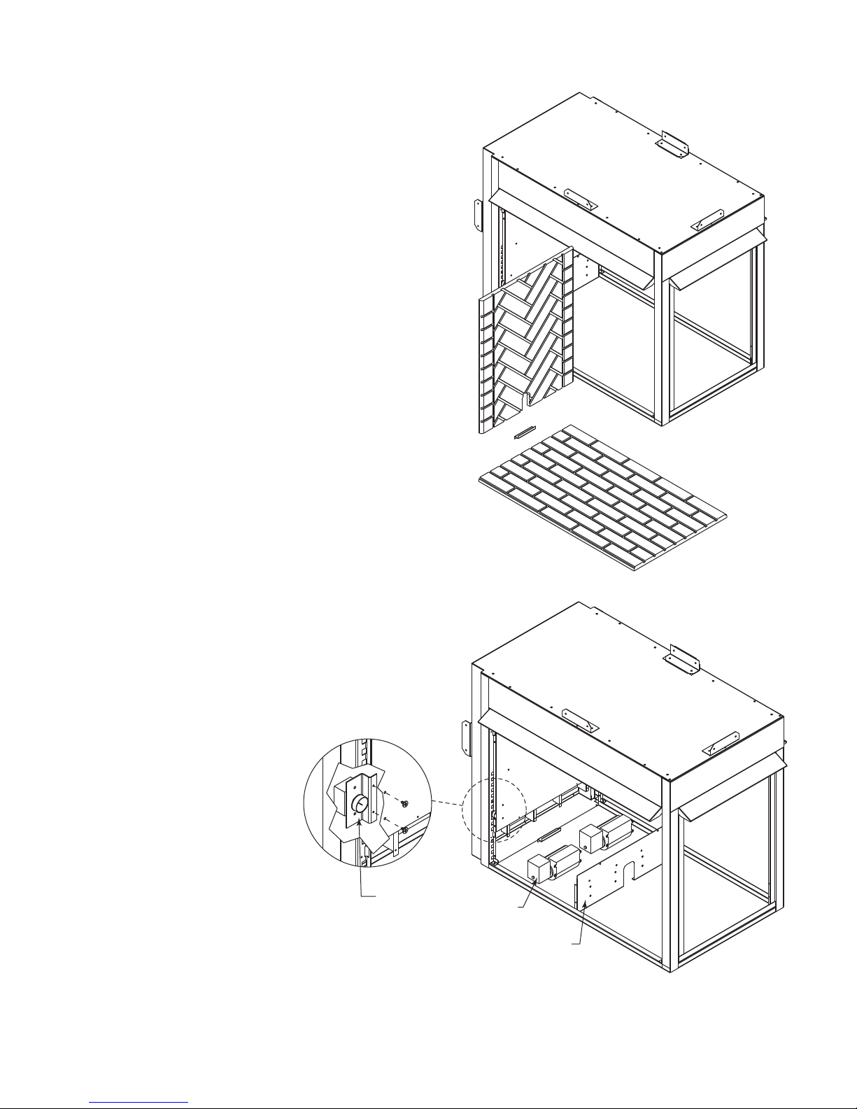
2. Remove brick wall(s) and hearth oor. Figure 3
3. Remove blower access/mounting plate. Figure 3
4. Mount the blower to the mounting plate by using the four (4) rubber grommets between the blower and plate. Attach with four (4)
#14 x 3/4 screws. Figure 5. NOTE: The blower may be mounted
on either side of unit according to which side the air is to be
discharged.
Install Thermal Sensor
NOTE: There are two (2) thermal sensors packed with this kit. Be
sure to install the correct sensor. Figure 6
1. Remove the thermal sensor plate located inside at top of replace on the air channel. Figure 4
2. Route the two (2) thermal sensor wires down through the air
channel to the bottom blower compartment of the unit. Align
the thermal sensor and attach to the sensor mounting plate
with screws provided. After the sensor is mounted reinstall the
mounting plate with the screws previously removed. Figure 4
Attach Speed Control
1. Slide the speed control knob through slot from under the blower
compartment. Align mounting holes in side panel to mounting
bracket. Use two (2) #8 x 1/2 screws to attach. Figure 5
2. Connect wiring according to the wiring diagram. Figure 2
WARNING: It is important to wire tie the loose wires and arrange
the wiring harness neatly so the wires cannot come in contact
with blower fan blades.
3. Plug power cord into junction box.
4. Reinstall blower access panel/mounting plate with blowers installed.
5. Reinstall brick, burner and logs in reverse order of removal.
6. To operate blower, turn replace ON. Turn the knob on the
speed control clockwise. The blower should be operating
at the highest speed within 10 minutes. Continue to turn the knob until
it reaches the desired speed. If the
low speed is set too low, it can be
adjusted. Figure 6
KT1353
Figure 2 Brick Removal
2
Speed
Control
Figure 3 Speed Control Installation
Blower
Blower Access /
Mounting Plate
KT1354
79D0009
Page 3

BLACKBLACKWHITE
GREEN
BLACK BLACK
WHITE
Receptacle
Junction
Box
120VAC
Speed Control
Thermal Sensor
Plate
Figure 4 Thermal Sensor Installation
Thermal Sensor
KT1355
79D0009
Figure 5 Blower Wiring Diagram
Adjustment
Screw
KT506
Figure 6 Location of Low Speed Setting
Adjustment Screw
FP2675
3
Page 4

Installation Instructions - LDV (ST, CL, CR,
PF)
NOTE: At the time of replace installation (before fram-
ing), the blowers can be installed through the end access
panel. Figure 7
1. Remove the lower access panel by pulling up and
away from unit.
2. Remove the glass frame by releasing the three (3)
latches below the rebox opening. Lift glass frame up
and away from unit.
3. Remove logs and grate.
4. Remove wall brick panels if installed and metal false
hearth oor.
5. Remove the four (4) screws, one in each corner of the
end cover panel at the end closest to the pilot. Figure
7
area and mount the speed control by rst removing
the knob, wall bracket and nut. Slide the control stem
through the hole and secure with the nut and replace
the knob. Figure 8
Figure 8 Speed Control
10. Install Thermal Sensor:
NOTE: There are two (2) thermal sensors packed in
this kit. Be sure to install the correct sensor. Figure 9
The sensor holding clip is located behind the square
plate on the end wall closest to the pilot. There is one
on each side. Choose the one on the same side as the
speed control. Remove the two (2) outer screws holding the plate and remove from wall. Replace gasket if
needed with new gasket provided. Slide the thermal
sensor into the clip until it snaps in place. Make sure
the terminals on the thermal sensor are perpendicular
to the clip. Figure 9. Route the two (2) sensor wires
down through the blower air channel to the lower access area. Reattach the sensor plate to wall.
Figure 7
6. Remove the blower mounting bracket from under the
oor of replace by removing the two (2) screws in the
oor for each bracket. Figure 7
7. Mount the blower to the mounting bracket with the #14
x 3/4 screws provided. Figure 7. NOTE: The blower
may be mounted on either side of unit according to
which side the air is to be discharge.
8. Slide the blower mounting brackets with blower in-
stalled through the access door or before framing in
the replace, through the end access panel. Reassemble blower mounting bracket with the screws removed.
9. Attach the Speed Control: Bend one of the mount-
ing tabs up 90° on the oor of the replace access
4
Clip
Thermal Sensor
Figure 9 Thermal Sensor
Installation
11. Connect wiring according to the wiring diagram shown
in Figure 5.
WARNING: It is important to wire tie loose wires and arrange the wiring harness neatly so the wires cannot come
in contact with blower fan blades.
12. Plug the power cord to the junction box.
13. Reinstall end cover wall, false hearth oor, rebrick,
grate, logs and glass in reverse order of removal.
14. To operate the blower, turn replace ON. Turn the
knob on the speed control clockwise. The blower
should be operating at the highest speed within 10
minutes. Continue to turn the knob until it reaches the
desired speed. If the low setting is set too low, it can
be adjusted. Figure 6
Vermont Castings Group
149 Cleveland Drive • Paris, Kentucky 40361
www.vermontcastingsgroup.com
79D0009
 Loading...