

Vermont Castings INDVRCBSB, INDVRBSSB, INDVRBMSB, INDVRBDSB Installation And Operating Instructions Manual
Page 1
DANGER
HOT GLASS WILL
CAUSE BURNS.
DO NOT TOUCH GLASS
UNTIL COOLED.
NEVER ALLOW CHILDREN
TO TOUCH GLASS.
A barrier designed to reduce the risk of burns from the hot
viewing glass is provided with this appliance and shall
be installed for the protection of children and
other at risk individuals.
20306543
CERTIFIED
SAFETY BARRIER
Intrepid® Direct Vent Gas Heater
Installation and Operating Instructions
Model: INDVRCBSB, INDVRBSSB, INDVRBMSB, INDVRBDSB
WARNING:
FIRE OR EXPLOSION HAZARD
Failure to follow safety warnings exactly
could result in serious injury, death or
property damage.
• Do not store or use gasoline or other
ammable vapors and liquids in the
vicinity of this or any other appliance.
• WHAT TO DO IF YOU SMELL GAS
– Do not try to light any appliance.
– Do not touch any electrical switch; do
not use any phone in your building.
– Leave the building immediately.
– Immediately call your gas supplier from
a neighbor's phone. Follow the gas
supplier's instructions.
– If you cannot reach your gas supplier,
call the re department.
• Installation and service must be performed
by a qualied installer, service agency or
the gas supplier.
WARNING: Improper installation, adjustment,
alteration, service or maintenance can cause
injury or property damage. Refer to this manual.
For assistance or additional information consult
a qualified installer, service agency or the
gas supplier.
This appliance may be installed in an aftermarket,
permanently located, manufactured home (USA
only) or mobile home, where not prohibited by
local codes.
This appliance is for use only with the type of gas
indicated on the rating plate. This appliance is
not convertible for use with other gases, unless
a certied kit is used.
INSTALLER: Leave this manual with the appliance.
CONSUMER: Retain this manual for future
reference.
20306761 12/14 Rev. 1
Page 2

Intrepid® Direct Vent - Rear Vent Gas Heater
Table of Contents
Thank you and congratulations on your purchase of a Vermont Castings stove.
PLEASE READ THE INSTALLATION & OPERATING INSTRUCTIONS BEFORE USING APPLIANCE.
IMPORTANT: Read all instructions and warnings carefully before starting installation. Failure to follow these
instructions may result in a possible re hazard and will void the warranty.
INSTALLATION AND OPERATING INSTRUCTIONS
General Information. .. . .. . .. . .. . .. . .. . .. . .. . .. . .. . .. . .. . .. . 3
Requirements for the Commonwealth of Massachusetts......4
Stove Dimensions..........................................5
Installation Requirements ..................................6
Locating the Stove .........................................6
Clearance Requirements ...................................6
Minimum Clearances, Parallel Installation,
Corner Installation. . .. . .. . .. . .. . .. . .. . .. . .. . .. . .. . .. . 7
Wall and Ceiling Clearances ...............................7
Mantel Clearances. . .. . .. . .. . .. . .. . .. . .. . .. . .. . .. . .. . .. . .. . 7
Hearth Requirements ......................................7
Gas Specications .........................................8
Air Shutter Setting .........................................8
Gas Inlet and Manifold Pressures ...........................8
High Elevations. . .. . .. . .. . .. . .. . .. . .. . .. . .. . .. . .. . .. . .. . .. . 8
Horizontal Termination .....................................8
Vertical Termination . .. . .. . .. . .. . .. . .. . .. . .. . .. . .. . .. . .. . .. . 9
Restrictor Plate Adjustment for Extended Pipe Runs .. . .. . .. . 9
Vent Termination Clearances ..............................10
Termination Location ......................................11
Termination Clearances .. . .. . .. . .. . .. . .. . .. . .. . .. . .. . .. . .. 12
MAINTENANCE
Annual System Inspection. .. . .. . .. . .. . .. . .. . .. . .. . .. . .. . .. 37
Log set and Burner Cleaning ..............................37
Care of Cast Iron .. . .. . .. . .. . .. . .. . .. . .. . .. . .. . .. . .. . .. . .. 37
Cleaning the Glass .......................................37
Glass Replacement . .. . .. . .. . .. . .. . .. . .. . .. . .. . .. . .. . .. . .. 37
Gasket Replacement......................................38
Inspect the Vent System Annually ..........................38
Check the Gas Flame Regularly ...........................38
Stove Disassembly .......................................38
Wiring Diagrams. .. . .. . .. . .. . .. . .. . .. . .. . .. . .. . .. . .. . .. . .. 39
REPLACEMENT PARTS . .. . .. . .. . .. . .. . .. . .. . .. . .. . .. . .. 41
OPTIONAL ACCESSORIES . .. . .. . .. . .. . .. . .. . .. . .. . .. . .. 42
WARRANTY .............................................43
EFFICIENCIES ...........................................44
INSTALLATION
Install Optional FK20 Fan Kit ..............................13
Venting System Components. .. . .. . .. . .. . .. . .. . .. . .. . .. . .. 14
Venting System Assembly, General Information,
Options, Planning .................................15
Rear Vent ................................................16
Horizontal Installation .....................................17
Vertical Installation. . .. . .. . .. . .. . .. . .. . .. . .. . .. . .. . .. . .. . .. 19
Cathedral Ceiling Installation ..............................21
General Maintenance .....................................22
Supplemental Canadian Instructions .. . .. . .. . .. . .. . .. . .. . .. 22
Vertical Through Existing Chimney .........................22
Converting a Class-A Metal Chimney or Masonry
Chimney to a Direct Vent System....................25
Connect Gas Supply Line .................................27
Burner Information ........................................28
Complete the Assembly .. . .. . .. . .. . .. . .. . .. . .. . .. . .. . .. . .. 28
Install ON/OFF Switch . .. . .. . .. . .. . .. . .. . .. . .. . .. . .. . .. . .. 28
Install the Front Plate......................................28
Thermostat Connection .. . .. . .. . .. . .. . .. . .. . .. . .. . .. . .. . .. 28
Install the Log Set.........................................29
Safety Barrier Installation .................................30
OPERATION
Your First Fire .. . .. . .. . .. . .. . .. . .. . .. . .. . .. . .. . .. . .. . .. . .. 31
Pilot and Burner Inspection ................................31
Flame & Temperature Adjustment ..........................31
Flame Characteristics .....................................31
Extension Knobs. .. . .. . .. . .. . .. . .. . .. . .. . .. . .. . .. . .. . .. . .. 31
Lighting and Operating Instructions ........................32
Troubleshooting ..........................................33
Fuel Conversion Instructions ..............................34
2
20306761
Page 3
Intrepid® Direct Vent - Rear Vent Gas Heater
Installation & Operating Instructions
The Intrepid Direct Vent room Heater, Model INDVR is a vented
gas appliances listed to ANSI Standard Z21.88-2005 and CSA-
2.33-2005 for Vented Room Heaters, and CSA 2.17-M91, GasFired Appliances For Use at High Altitudes.
The installation of the Intrepid Direct Vent Room Heater must
conform with local codes, or in the absence of local codes, with
National Fuel Gas Code, ANSI Z223.1/NFPA 54 — latest edition
and CSA B-149.1 (EXCEPTION: Do not derate this appliance for
altitude. Maintain the manifold pressure at 3.5” w.c. for Natural
Gas and 10” w.c. for LP gas at maximum input.) Refer to page
8 (RF only).
This appliance is only for use with the type of gas indicated on the
rating plate. This appliance is not convertible for use with other
gases unless a certied kit is used.
Installation and replacement of gas piping, gas utilization
equipment or accessories, and repair and servicing of equipment shall be performed only by a qualied agency, preferably
NFI or WETT (Canada) certied. The term “qualied agency”
means any individual, rm, corporation, or company that
either in person or through a representative is engaged in
and is responsible for (a) installation or replacement of gas
piping, or (b), the connection, installation, repair, or servicing of equipment, who is experienced in such work, familiar
with all precautions required, and has complied with all the
requirements of the authority having jurisdiction.
The Intrepid Direct Vent Room Heater should be inspected
before use and at least annually by a qualied service agency.
It is imperative that control compartments, burners, and circulating air passageways of the appliance be kept clean.
The Intrepid Direct Vent Room Heater and the individual shut-off
valve must be disconnected from the gas supply piping during
any pressure testing of that system at test pressures in excess
of 1/2 psig (3.5 kPa).
The Intrepid Direct Vent Room Heater must be isolated from the
gas supply piping system by closing the individual manual shutoff
valve during any pressure testing of the gas supply piping system
at test pressures equal to or less than 1/2 psig.
An accessible tap is located above the pilot/on-off knob for checking the inlet pressure.
‘Direct Vent’ describes a sealed combustion system in which incoming outside air for combustion and outgoing exhaust enter and
exit through two separate concentric passages within the same
sealed vent system. The system does not use room air to support
combustion. The Direct Vent system permits the gas appliance to
be vented directly to the outside atmosphere through the side of
the house or vertically through the roof.
This appliance is approved for bedroom installations in the U.S.
and Canada.
This appliance may be installed in an aftermarket* manufactured
(mobile) home, where not prohibited by state or local codes.
WARNING: Operation of this heater when not connected to a
properly installed and maintained venting system can result
in carbon monoxide (CO) poisoning and possible death.
The Intrepid Direct Vent Room Heater, when installed, must be
electrically grounded in accordance with local codes or, in the
absence of local codes, with the National Electrical Code ANSI/
NFPA 70, (latest edition), or of the current Canadian Electrical
Code C22.1.
Due to high temperatures this appliance should be located
out of trafc and away from furniture and draperies.
WARNING: This appliance is hot while in operation. Keep
children, clothing, and furniture away. Contact may cause
burns or ignition of combustible materials.
Children and adults should be alerted to the hazards of high
surface temperatures and should stay away to avoid burns
or clothing ignition. Young children should be carefully supervised when they are in the same room as the appliance.
Clothing or other ammable materials should not be placed
on or near the appliance.
Any safety screen, glass or guard removed for servicing an
appliance must be replaced prior to operating the appliance.
The appliance area must be kept clear and free from combustible materials, gasoline, and other ammable vapors
and liquids.
The ow of combustion and ventilation air must not be obstructed. The installation must include adequate accessibility
and clearance for servicing and proper operation.
WARNING: Do not operate the Room Heater with the glass
panel removed, cracked or broken. Replacement of the panel
should be done by a licensed or qualied service person.
Do not use this appliance if any part has been under water.
Immediately call a qualied service technician to inspect the
appliance and to replace any part of the control system and
any gas control which has been under water.
Do not burn wood, trash or any other material for which this
appliance was not designed. This appliance is designed to
burn either natural gas or propane only.
This gas appliance must not be connected to a chimney ue
serving a separate solid-fuel burning appliance.
CAUTION: Label all wires prior to disconnection when
servicing controls. Wiring errors can cause improper and
dangerous operation.
Verify proper operation after servicing.
* Aftermarket: Completion of sale, nor for purpose of resale,
from the manufacturer.
Intrepid
Direct Vent / Rear Vent
Certied to:
ANSI Z21.88-2014 / CSA Z2.33-2014
Vented Gas Fireplace Heaters
Proposition 65 Warning: Fuels used in gas, woodburning or
oil red appliances, and the products of combustion of such
fuels, contain chemicals known to the State of California to
cause cancer, birth defects and other reproductive harm.
California Health & Safety Code Sec. 25249.6
20306761
3
Page 4

Intrepid® Direct Vent - Rear Vent Gas Heater
Installation & Operating Instructions
Requirements for the Commonwealth of
Massachusetts
All gas tting and installation of this heater shall only be
done by a licensed gas tter or licensed plumber.
For all side wall horizontally vented gas fueled equipment
installed in every dwelling, building or structure used in whole
or in part for residential purposes, including those owned
or operated by the Commonwealth and where the side wall
exhaust vent termination is less than seven (7) feet above
nished grade in the area of the venting, including but not
limited to decks and porches, the following requirements
shall be satised:
Installation of Carbon Monoxide Detectors
At the time of installation of the side wall horizontal vented
gas fueled equipment, the installing plumber or gas tter
shall observe that a hard wired carbon monoxide detector
with an alarm is installed on each additional level of the
dwelling, building or structure served by the side wall
horizontally vented gas fueled equipment. It shall be the
responsibility of the property owner to secure the services
of qualied licensed professionals for the installation of
hard wired carbon monoxide detectors.
In the event that the side wall horizontally vented gas fueled
equipment is installed in a crawl space or an attic, the hard
wired carbon monoxide detector with alarm and battery
back-up may be installed on the next adjacent oor level.
In the event that the requirements of this subdivision can not
be met at the time of completion of installation, the owner
shall have a period of thirty (30) days to comply with the
above requirements; provided, however, that during said
thirty (30) day period, a battery operated carbon monoxide
detector with an alarm shall be installed.
Approved Carbon Monoxide Detectors
Each carbon monoxide detector as required in accordance
with the above provisions shall comply with NFPA 720 and
ANSI/UL 2034 listed and IAS certied.
Signage
A metal or plastic identication plate shall be permanently
mounted to the exterior of the building at a minimum height
of eight (8) feet above grade directly in line with the exhaust
vent terminal for the horizontally vented gas fueled heating
appliance or equipment. The sign shall read, in print size no
less than one-half (1/2) inch in size, “GAS VENT DIRECTLY
BELOW, KEEP CLEAR OF ALL OBSTRUCTIONS”.
Inspection
The state or local gas inspector of the side wall horizontally
vented gas fueled equipment shall not approve the
installation unless, upon inspection, the inspector observes
carbon monoxide detectors and signage installed in
accordance with the provisions of 248 CMR 5.08(2)(a)1
through 4.
Exemptions
The following equipment is exempt from 248 CMR
5.08(2)(a)1 through 4:
• The equipment listed in Chapter 10 entitled “Equipment
Not Required To Be Vented” in the most current edition
of NFPA 54 as adopted by the Board; and
• Product Approved side wall horizontally vented gas fueled
equipment installed in a room or structure separate from
the dwelling, building or structure used in whole or in
part for residential purposes.
MANUFACTURER REQUIREMENTS
Gas Equipment Venting System Provided
When the manufacturer of Product Approved side wall
horizontally vented gas equipment provides a venting
system design or venting system components with the
equipment, the instructions provided by the manufacturer
for installation of the equipment and the venting system
shall include:
• Detailed instructions for the installation of the venting
system design or the venting system components;
and
• A complete parts list for the venting system design or
venting system.
Gas Equipment Venting System NOT Provided
When the manufacturer of a Product Approved side wall
horizontally vented gas fueled equipment does not provide
the parts for venting the ue gases, but identies “special
venting systems”, the following requirements shall be
satised by the manufacturer:
• The referenced “special venting system” instructions shall
be included with the appliance or equipment installation
instructions; and
• The “special venting systems” shall be Product
Approved by the Board, and the instructions for that
system shall include a parts list and detailed installation
instructions.
A copy of all installation instructions for all Product Approved
side wall horizontally vented gas fueled equipment, all
venting instructions, all parts lists for venting instructions,
and/or all venting design instructions shall remain with
the appliance or equipment at the completion of the
installation.
4
20306761
Page 5
Intrepid® Direct Vent - Rear Vent Gas Heater
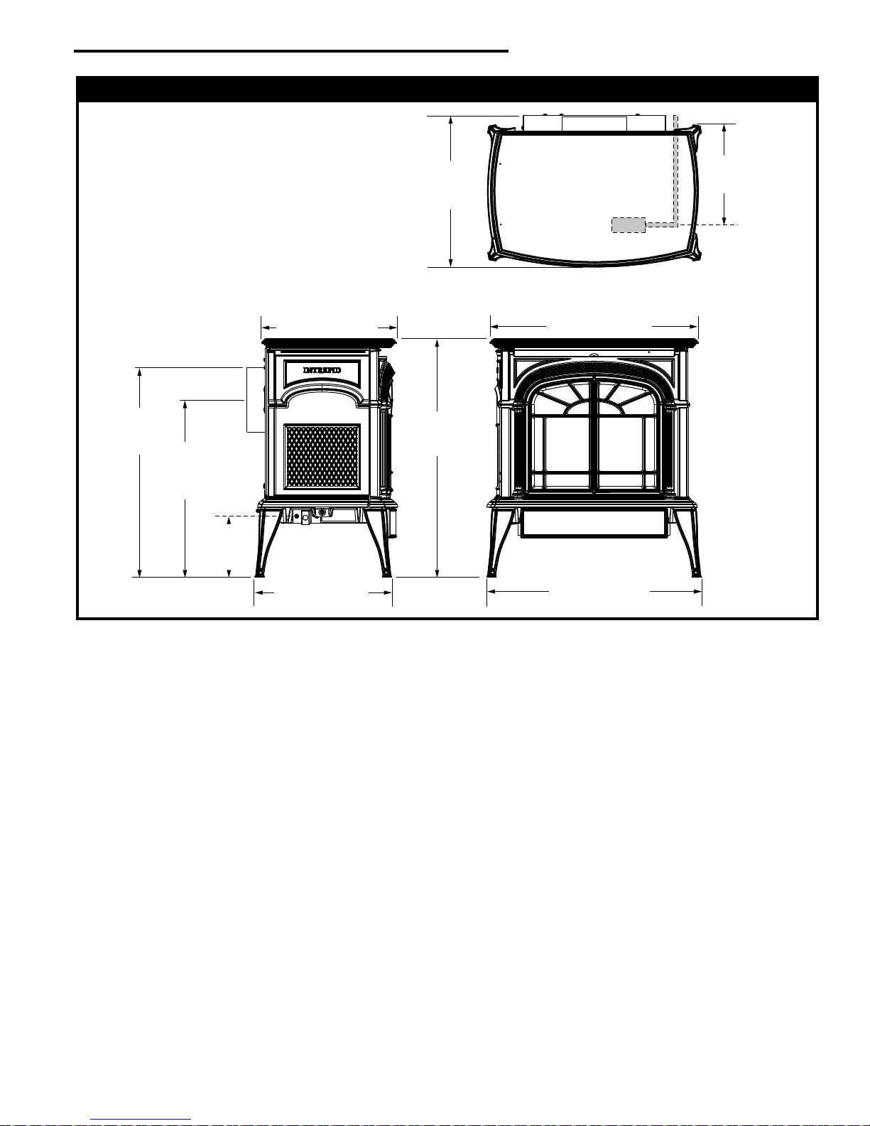
Intrepid Stove Dimensions
21³⁄₈"
(543 mm)
Centerline
of Flue Pipe
18”
(457 mm)
Valve Inlet
C
L
(102 mm)
4”
13¹¹⁄₁₆” (347 mm)
16⁷⁄₁₆”
(418 mm)
24¹⁄₄”
(616 mm)
21³⁄₁₆” (538 mm)
6¹⁄₂”
(165 mm)
C
Valve
Inlet
L
Fig. 1 Intrepid dimensions.
13⁷⁄₈” (352 mm)
21³⁄₄” (553 mm)
20306761
5
Page 6
Intrepid® Direct Vent - Rear Vent Gas Heater
Installation Requirements
The installation must conform with local codes or, in the
absence of local codes, with the National Fuel Gas Code,
ANSI Z223.1/NFPA 54 - latest edition. (EXCEPTION: Do
not derate this appliance for altitude. Maintain the manifold pressure at 3.5 inches w.c. for Natural Gas, and 10
inches w.c. for Propane).
In Canada, installation must be in accordance with the
current CSA B-149.1 Installation Codes and/or local
codes.
The installation should be done by a qualied service
person who is familiar with the building codes and
installation techniques appropriate for your area to
accomplish a safe and effective installation.
Your dealer or your local gas supplier will be able to
refer a qualied service person.
WARNING: Due to high temperatures, the
HEATER should be located out of trafc and
away from furniture and draperies.
The surface of the Heater is hot when it is in use.
Young children should be watched carefully when
they are in the same room when the Heater is in use,
and they should be taught to avoid the hot surface.
Keep any objects that can burn well away from the
Heater, and observe the recommended clearances
that follow.
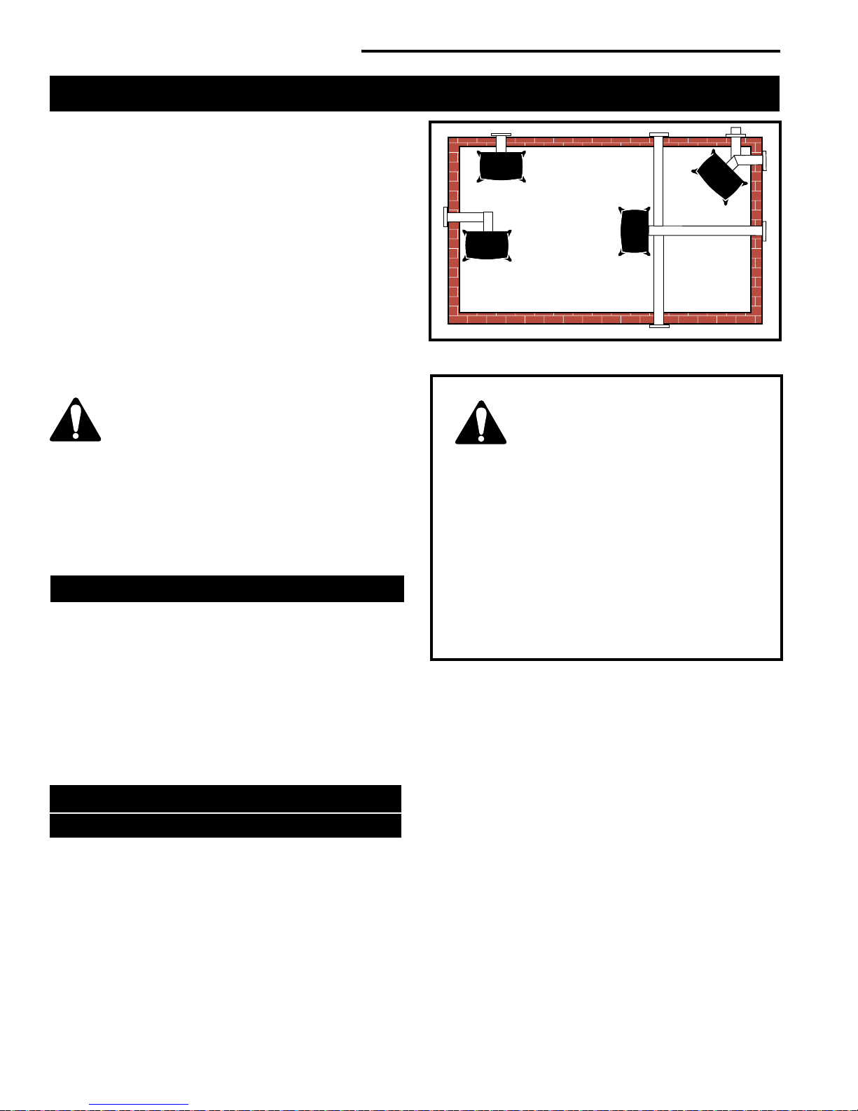
Locating the Stove
In choosing a location for the stove, consider:
• The location of outside walls;
• Where additional heat is needed:
• Where family members gather most often;
• The vent system requirements.
NOTE: We do not recommend the use of wallpaper next
to this stove. Over time, radiant heat may cause the wallpaper to shrink, or may adversely affect the binders in the
wallpaper adhesive.
A
B
Fig. 2 Possible stove locations.
C
D
ST942
WARNING:
Always maintain required clearances
(air spaces) to nearby combustibles to
prevent re hazard. Do not ll air spaces
with insulation. All venting components
must maintain a 1” (25 mm) clearance to combustible materials. Maintain a 6” (152 mm) clearance
when using single wall pipe. Maintain a 2” (51
mm) clearance on top and 1” (25 mm) on sides
and bottom when venting straight off the rear.
• The gas appliance and vent system must be
vented directly to the outside of the building
and never be attached to a chimney serving a
separate solid fuel or gas-burning appliance.
• Refer to the manufacturer’s instructions included
with the venting system for complete installation
procedures.
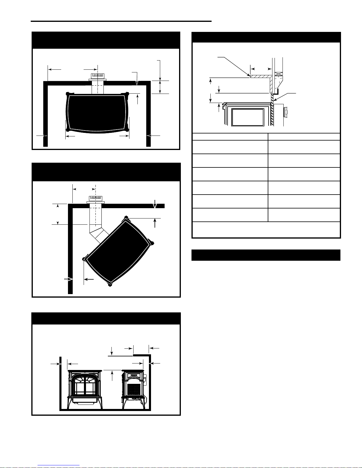
Clearance Requirements
Minimum Clearances to Combustible Materials
Measure side clearances as shown in Figures 3, 4 and 5
from the outer edge of the cast iron stove top. Measure
rear clearances from the outermost surface of the steel
rear skirt.
This heater is approved for installation into an alcove constructed of combustible materials to the dimensions and
clearances shown on the next page.
The same clearances apply in a standard parallel installation.
6
20306761
Page 7
Intrepid® Direct Vent - Rear Vent Gas Heater
C
L
18³⁄₄"
(476 mm)
2¹⁄₂"
(64 mm)
4"
(102 mm)
4"
(102 mm)
Max. Vent
Length
24” (610 mm)
2" (51 mm)
2"
(51 mm)
7¹⁄₂"
(190 mm)
Max. Vent
Length
24" (610 mm)
9"
(230 mm)
Max. Mantel
Width
Refer to
Fig. 6
4"
(102 mm)
Sidewall/
Trim
2¹⁄₂"
(63 mm)
Rear Wall
A
B
3" (75mm) Min.
Parallel Installation: Minimum Clearance
and Flue Centerline
ST947
Fig. 3 Parallel Installation, minimum back and side clearance.
Corner Installation: Minimum Clearance and
Flue Centerline
Mantel Clearances
Combustible
Mantel or Trim
Materials
Noncombustible
Materials
ST382
A (Max.) B (Min.)
9" 10
(230 mm) (270 mm)
71⁄2" 9"
(190 mm) (230 mm)
6" 71⁄2"
(152 mm) (190 mm)
41⁄2" 6"
(114 mm) (152 mm)
3" 41⁄2"
(76 mm) (114 mm)
11⁄2" 3"
(38 mm) (76 mm)
A = Depth of Mantel and/or Top Trim
B = Height from Top of Heater
Fig. 6 Mantel / top trim clearances.
1
⁄2"
ST948
Fig. 4 Corner installation, minimum corner clearance and ue
centerline.
Wall and Ceiling Clearances
Fig. 5 Alcove and ceiling clearances.
20306761
ST949
Hearth Requirements
The Intrepid Heater must be installed on rigid ooring. When
the heater is installed directly on any combustible surface
other than wood ooring, a metal or wood panel extending
the full width and depth of the unit must be used as the
hearth. There are no other hearth requirements.
7
Page 8
Intrepid® Direct Vent - Rear Vent Gas Heater
20
19
18
16
15
14
13
12
11
10
9
8
7
6
5
4
3
2
1
0
1 2 3 4 5 6 7 8 9 10 11 12 13 14 15 16 17 18 19 20
Vertical Run (in feet)
Measured after the first elbow. (Transition elbow)
Horizontal Run (in feet)
21
22
23
24
25
26
27
28
29
30
ST134a
FDV28
Horizontal
vent run
12/3/99 djt
areas modified
1/11/00 djt
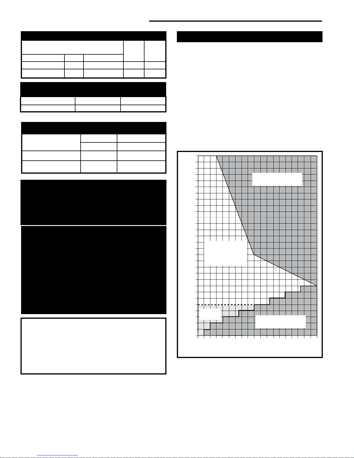
Gas Specications
Max. Min.
Input Input
Model Fuel Gas Control BTU/h BTU/h
INDVR Series Nat Millivolt 18,500 12,500
INDVR Series Prop Millivolt 16,000 12,000
Air Shutter Setting
Minimum injector air inlet opening
Model Natural Gas LP
INDVR 1/2” Open 1/2” Open
Weight: Fully assembled 350 lbs.
Gas Inlet and Manifold Pressures
Natural LP (Propane)
Inlet Minimum 5.5” w.c. 11.0” w.c.
Inlet Maximum 14.0” w.c. 14.0” w.c.
Manifold Pressure 3.5” w.c. 10” w.c.
The installation must conform with local codes or, in the
absence of local codes, with the National Fuel Gas Code,
ANSI Z223.1/NFPA 54 - latest edition. (EXCEPTION:
Do not derate this appliance for altitude. Maintain the
manifold pressure at 3.5” w.c. for Natural Gas and 10”
w.c. for Propane.)
Horizontal Termination
Except for straight-through the wall vent installations.
The vent must rise vertically a minimum of 24” (610 mm)
after the rst elbow directly off the back of the unit, before
the next elbow. The horizontal run may extend up to 20’ (6
m) and include a vertical rise of up to 40’ (12 m). (Fig. 7)
Horizontal termination must also meet the criteria shown
in Figures 11 and 12.
• Approved vent systems must terminate above and
including the heavy line in Figure 7.
• Two 45° elbows may be substituted for each single 90˚
elbow.
• With a rise between 2’ - 5’, one 90° or two 45° elbows
may be used (Excluding the rst elbow directly off the
back of the unit.
Unacceptable
Venting Conguration
High Elevations
Input ratings are shown in BTU per hour and are
certied without deration for elevations up to 4,500
feet (1,370m) above sea level.
For elevations above 4,500 feet (1,370m) in USA,
installations must be in accordance with the current ANSI Z223.1/NFPA 54 and/or local codes having
jurisdiction.
In Canada, please consult provincial and/or local
authorities having jurisdiction for installations at
elevations above 4,500 feet (1,370m).
WARNING: Improper installation, adjustment,
alteration, service or maintenance can cause
injury or property damage. Refer to this manual
for correct installation and operational procedures. For assistance or additional information
consult a qualied installer, service agency, or
the gas supplier.
8
May use up to
four 90° Elbows
(Including elbow
directly off back of
unit.)
Two 90°
Elbows
Unacceptable
Venting Conguration
Fig. 7 Horizontal vent termination window.
ST134f
20306761
Page 9
Intrepid® Direct Vent - Rear Vent Gas Heater
20
19
18
16
15
14
13
12
11
10
9
8
7
6
5
4
3
2
1
0
20
1 2 3 4 5 6 7 8 9 10 11 12 13 14 15 16 17 18 19
Vertical Run (in feet)
(Measured after the first elbow. (Transition elbow)
Horizontal Run (in feet)
21
22
23
24
25
26
27
28
29
30
31
32
33
34
35
36
37
38
39
40
ST132f
Pinstar
Vertical
vent run
10/9/00 djt
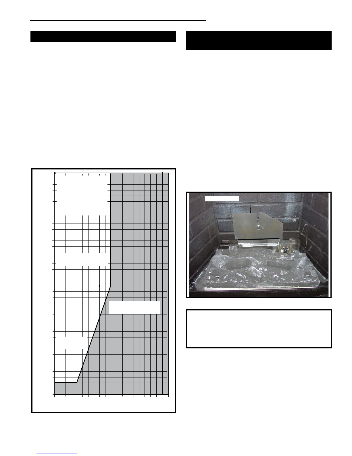
Vertical Termination
A vertical vent system must terminate no less than 8’
(2.44 m) and no more than 40’ (12 m) above the appli-
ance ue collar. A restrictor plate (supplied) must be used
(where specied) in all vertically terminated vent systems.
NOTE: The restrictor plate supplied with the vertical
termination kit should be discarded. Install restrictor
plate according to recommendations in Figure 10. A
vertically terminated vent system must also conform to the
following criteria:
• No more than three 90° elbows may be used.
• Two 45° elbows may be substituted for one 90° elbow.
No more than six elbows may be used.
• Vent must rise a minimum of 2 feet before offset is
used.
• Termination height must conform to roof clearance as
specied in Figure 11.
All Vertical
Terminations in
this area Require use of the
Restrictor Plate*
Fig. 8 Vertical vent termination window.
20306761
Vertical terminations
must be within this area
Venting Conguration
No Restrictor
Plate
Unacceptable
ST132g
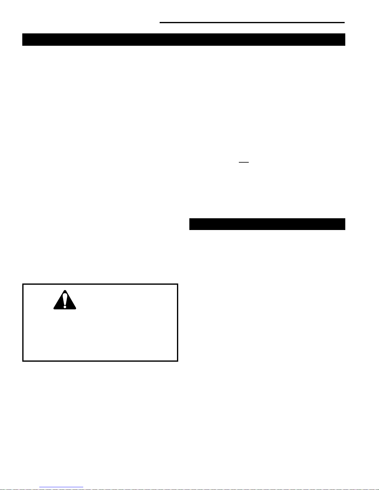
Restrictor Plate Adjustment
for Extended Pipe Runs
This stove is shipped with a restrictor plate in the Parts
Bag. Adjustments can be made by loosening the adjustment screw to allow the restrictor plate to slide up or down.
(Fig. 9) A guide for usage is shown in Figure 10.
NOTE: Some installations may require some adjustment
by the installer for optimum ame appearance. Optimum
ame appearance is a ame that is not subject to tall, dirty
yellow ames producing soot or ames lifting off of the
ember bed ports.
Restrictor Plate Adjustment
1. Remove the logs if installed.
2. Remove the adjustment screw in the back wall of the
rebox.
3. Install restrictor plate as shown in Figure 9 with angle
on plate on the top right side. Secure with adjustment
screw.
4. Adjust restrictor according to examples in Figure 10.
5. Install logs following log installation instructions.
Restrictor Plate
ST936
Fig. 9 Restrictor plate.
Examples for Extended Run/Restrictor Plate Settings top of plate to center of bolt
1. 90° elbow, 40’ (12 m) vertical - 2
2. 90° elbow, 20’ (6 m) vertical, 90° elbow, 8’ (2.4 m)
horizontal - 27⁄8" (73 mm)
Figure 10
7
⁄8" (73 mm)
9
Page 10
Intrepid® Direct Vent - Rear Vent Gas Heater
Vent Termination Clearances
When planning the installation, consider the location of the
vent terminal and clearances. Some of the most common
clearances to keep in mind are shown in Figure 11.
Important: All vent clearances must be maintained.
Check your vent termination clearances against Figures 11 and 12.
The vent should be placed so that people cannot be burned
by accidentally touching the vent surfaces when the stove
is operating.
The vent termination should be located where it cannot be
damaged by such things as automobile doors, lawn mowers
or snowblowers and it should be located away from areas
where it could become blocked by snow, etc.
Some considerations are:
• Obstructions or impediments to venting.
• Nearby combustible materials that could come into
contact with combustion exhaust gases.
• Other nearby openings {within 9” (230 mm)} through
which exhaust gas could reenter the building.
• All vegetation within 3’ (914 mm) that may interfere with
the draft.
Other factors that inuence where the installation will be
sited include the location of outside walls, where additional
heat may be desired in the home, where the family members gather most regularly, and perhaps most importantly,
the distance limitations of the venting system.
Your stove is approved to be vented either through the side
wall, or vertical through the roof.
• Vermont Castings Group does not require any open-
ing for inspection of vent pipe.
• Only venting components specically approved and
labelled for this stove may be used.
• Minimum clearances between vent pipes and com-
bustible materials is one (1”) inch (25mm), except
where stated otherwise.
• Venting terminals shall not be recessed into a wall or
siding.
• Horizontal venting must be installed on a level plane
without an inclining or declining slope.
There must not be any obstruction such as bushes, garden
sheds, fences, decks or utility buildings within 24” from the
front of the termination hood.
Do not locate termination hood where excessive snow or ice
build up may occur. Be sure to check vent termination area
after snow falls, and clear to prevent accidental blockage
of venting system. When using snow blowers, make sure
snow is not directed towards vent termination area.
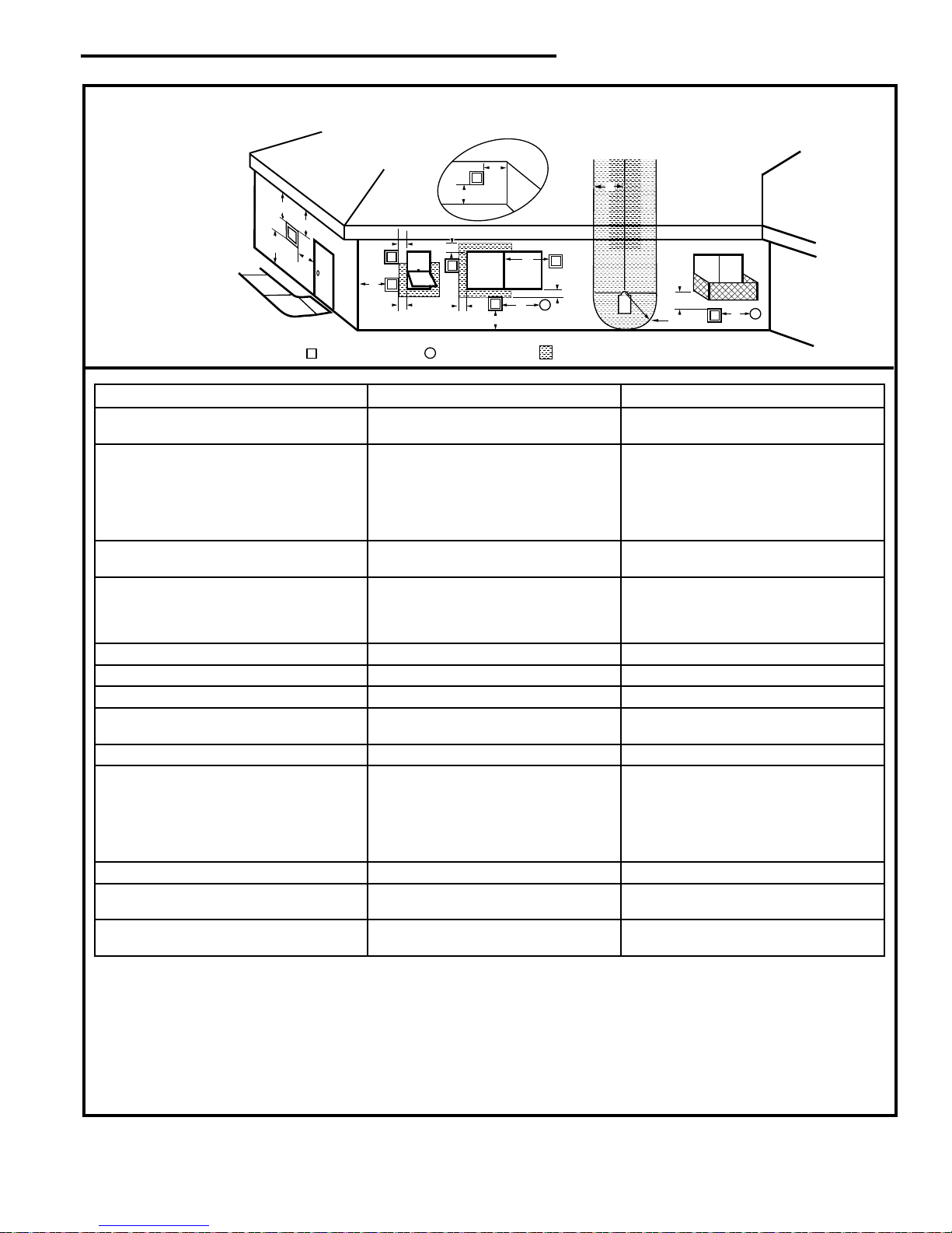
Location of Vent Termination
It is imperative the vent termination be located observing
the minimum clearances as shown in Figure 11.
IMPORTANT
• The horizontal termination must not be recessed
into the exterior wall or siding.
• Horizontal vent runs must be level toward the vent
termination.
• Clearances around the vent termination must be
maintained.
10
20306761
Page 11
V
X
X
X
D
E
B
B
B
C
B
M
B
A
J
K
F
L
VENT TERMINATION AIR SUPPLY INLET
AREA WHERE TERMINAL IS NOT PERMITTED
H
I
Fixed
Closed
Operable
Operable
Fixed
Closed
B
INSIDE
CORNER DETAIL
A
G
CFM145a
V
V
V
V
V
V
V
V
TERMINATION LOCATION
Figure 11 –
Termination Locations
Intrepid® Direct Vent - Rear Vent Gas Heater
A = Clearance above grade, veranda, porch,
CANADIAN INSTALLATIONS
1
12" (30cm) 12" (30cm)
US INSTALLATIONS
2
deck or balcony
B = Clearance to window or door that may be
opened
C = Clearance to permanently closed window 12" (305mm) recommended to prevent
D = Vertical clearance to ventilated soft
6" (15cm) for appliances <10,000 BTU/h
(3kW)
12" (30cm) for appliances >10,000 BTU/h
(3kW) and <100,000 BTU/h (30kW)
36" (91cm) for appliances >100,000 BTU/h
(30kW)
6" (15cm) for appliances <10,000 BTU/h
(3kW)
9" (23cm) for appliances >10,000 BTU/h
(3kW) and <50,000 BTU/h (15kW)
12" (30cm) for appliances >50,000 BTU/h
(15kW)
12" (305mm) recommended to prevent
window condensation
window condensation
18" (458mm) 18" (458mm)
located above the terminal within a horizontal distance of 2' (610 mm) from the
center line of the terminal
E = Clearance to unventilated soft 12" (305mm) 12" (305mm)
F = Clearance to outside corner see next page see next page
G = Clearance to inside corner see next page see next page
H = Clearance to each inside of center line
extended above meter/regulator assembly
3' (91cm) within a height of 15' (5m) above
the meter/regulator assembly
3' (91cm) within a height of 15' (5m) above
the meter/regulator assembly
I = Clearance to service regulator vent outlet 3' (91cm) 3' (91cm)
J = Clearance to non-mechanical air supply
inlet to building or the combustion air inlet
to any other appliance
6" (15cm) for appliances <10,000 BTU/h
(3kW)
12" (30cm) for appliances >10,000 BTU/h
(3kW) and <100,000 BTU/h (30kW)
36" (91cm) for appliances >100,000 BTU/h
(30kW)
6" (15cm) for appliances <10,000 BTU/h
(3kW)
9" (23cm) for appliances >10,000 BTU/h
(3kW) and <50,000 BTU/h (15kW)
12" (30cm) for appliances >50,000 BTU/h
(15kW)
K = Clearance to mechanical air supply inlet 6' (1.83m) 3' (91cm) above if within 10' (3m) horizontally
L = Clearance above paved sidewalk or
7' (2.13m)
†
7' (2.13m)
†
paved driveway located on public property
M = Clearance under veranda, porch, deck or
12" (30cm)
‡
12" (30cm)
‡
balcony
1 In accordance with the current CSA-B149 Installation Codes
2 In accordance with the current ANSI Z223.1/NFPA 54 National Fuel
Gas Codes
† A vent shall not terminate directly above a sidewalk or paved
driveway which is located between two single family dwellings and
serves both dwellings
‡ Only permitted if veranda, porch, deck or balcony is fully open on a
minimum 2 sides beneath the oor.
20306761
NOTE: 1. Local codes or regulations may require different clear-
2. The special venting system used on Direct Vent Fireplac-
3. Vermont Castings Group assumes no responsibility for
ances.
es are certied as part of the appliance, with clearances
tested and approved by the listing agency.
the improper performance of the appliance when the venting
system does not meet these requirements.
11
Page 12
Intrepid® Direct Vent - Rear Vent Gas Heater
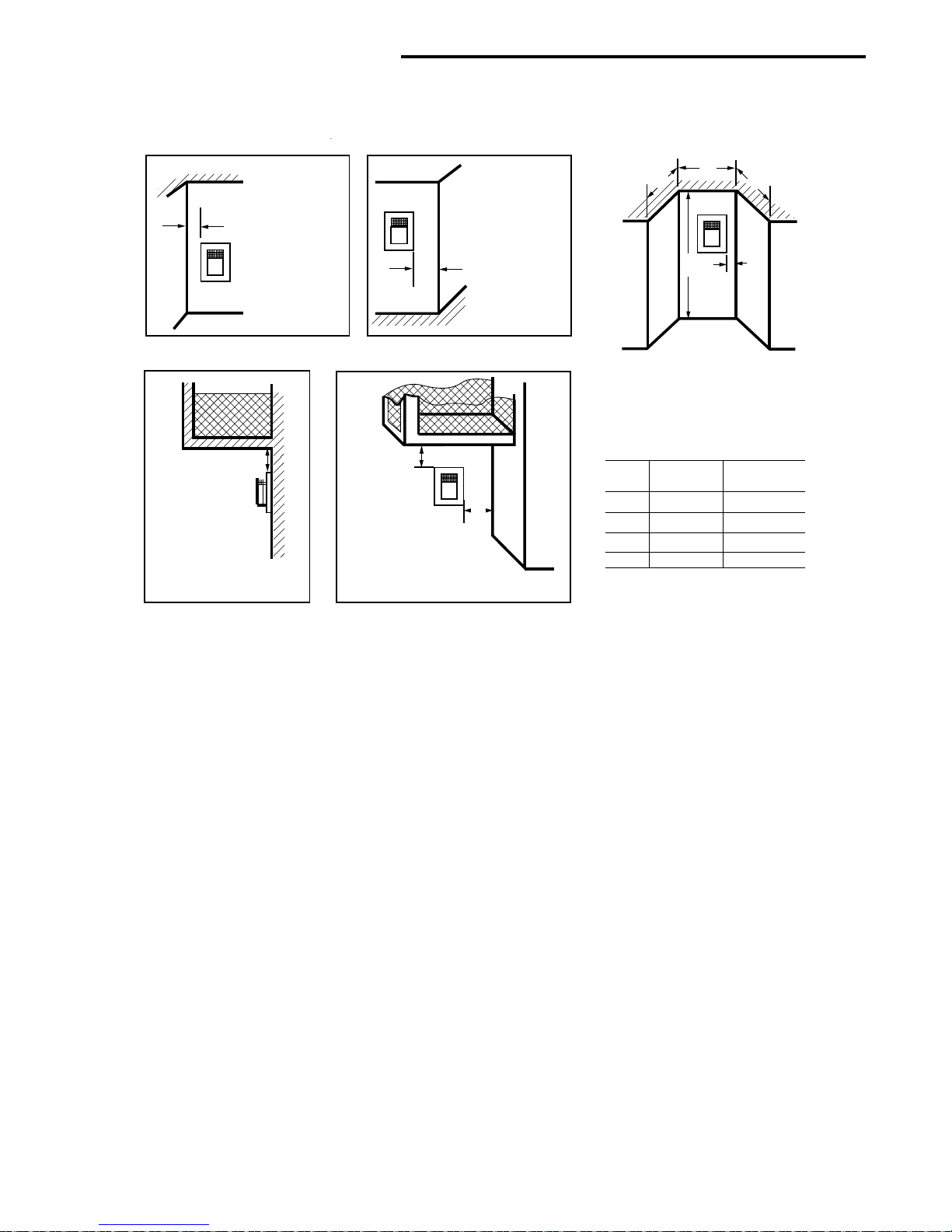
Outside Corner
Inside Corner
Termination Clearances
Termination clearances for buildings with combustible and noncombustible exteriors.
Alcove Applications*
TERMINATION CLEARANCES
Termination clearances for buildings with combustible and non-combustible exteriors.
F =
F
Combustible
6" (152 mm)
Noncombustible
2" (51 mm)
G =
G
Combustible
6" (152 mm)
Noncombustible
V
2" (51 mm)
V
C
D
C
V
O
E
Balcony -
with no side wall
M
V
Balcony -
with perpendicular side wall
M
V
P
M =
Combustible &
Noncombustible
12" (305 mm)
*NOTE: Termination in an alcove space (spaces open only on one side
and with an overhang) is permitted with the dimensions specied for
vinyl or non-vinyl siding and softs. 1. There must be a 3' (914 mm) min-
imum between termination caps. 2. All mechanical air intakes within 10'
Combustible &
Noncombustible
M = 12" (305 mm)
P = 6” (152 mm)
(1 m) of a termination cap must be a minimum of 3' (914 mm) below the
termination cap. 3. All gravity air intakes within 3' (914 mm) of a termination cap must be a minimum of 1' (305 mm) below the termination cap.
Fig. 12 Termination clearances.
E = Min. 2” (51 mm) for
non-vinyl sidewalls
Min. 12” (305 mm) for
vinyl sidewalls
O = 8’ (2.4 m) Min.
No. of
Caps D
1 3' (914 mm) 2 x Dactual
2 6' (1.8 m) 1 x Dactual
3 9' (2.7 m) 2/3 x Dactual
4 12' (3.7 m) 1/2 x Dactual
D
= Number of Termination caps x 3
Min.
C
= (2 / Number termination caps) x D
Max.
min. Cmax.
Actual
12
20306761
Page 13
Installation
A
Unpack the Stove
The stove is shipped fully assembled on its back. Unpack
the stove and carefully set it upright.
CAUTION
Porcelain enamelled surfaces are fragile. Handle porcelain enamelled castings tenderly. Familiarize yourself
with the assembly steps before you begin and proceed
with deliberation and care. If possible, have assistance
available.
Place enamelled castings on a soft, cushioned surface
until you are ready to assemble.
Avoid contact between the castings and other hard
surfaces or objects.
NOTE: Verify the two relief doors (located on top of the
rebox) are properly seated on the gasket. The doors
sit ush on the gasket, and should lift easily from the
seal around the opening.
Intrepid® Direct Vent - Rear Vent Gas Heater
Remove Four
(4) Screws
(Retain for
future use)
KT899
Fig. 13 Remove four (4) screws holding rear fan cover in
place. Retain for future use.
1/4-20 x 3/8’
Phillips Screw
If you are installing the fan, install it before completing the stove venting.
If you are not installing a fan, proceed to the appropriate vent assembly section.
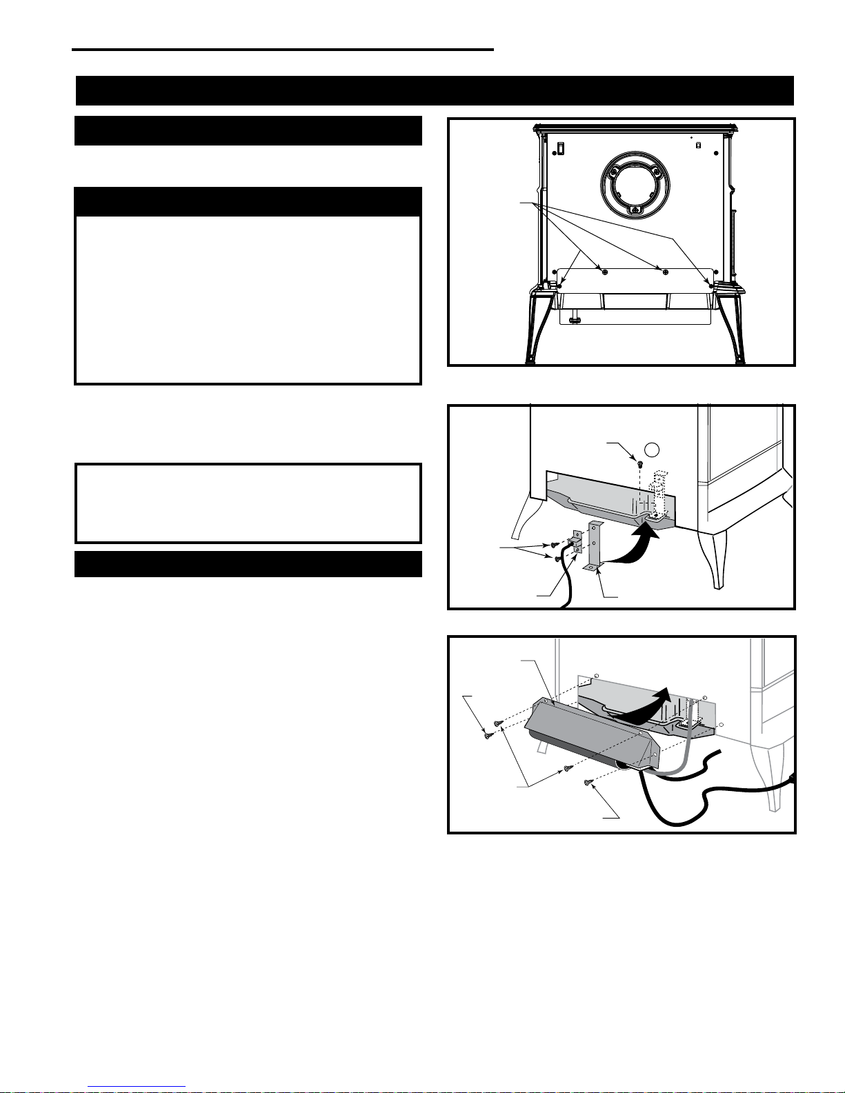
Install Optional Fan Kit FK20
Fan Kit Contents:
• #10 x 1/2” phillips screws, 2
• Control Knob • Wire Tie
• Retaining Nut • Snapstat
• Snapstat Bracket
• Blower Assembly w/ Rheostat Control & Snapstat
1. Remove the rear fan cover by removing the four (4)
screws holding the cover in place on the rear shroud.
(Fig. 13) Retain the screws for future use.
2. Attach the Snapstat to the bracket using two (2) #10 x
1/2” Phillips screws. (Fig. 14)
3. Locate and remove the 1/4-20 x 3/8” hex head bolt in-
stalled in the hole in the right rear ledge of the rebox. (A,
Fig. 14) Use that bolt to secure the snapstat bracket to
the rebox. The mounting hole is slotted to allow you to
adjust the bracket so the snapstat head makes contact
with the rebox surface. (Fig. 14)
4. Attach the fan to the rebox by reusing the two (2) pan
head 1/4-20 screws on the top edge and the two (2) #10
x 1/2” sheet metal screws on the side edges. (Fig. 15)
5. The rheostat control switch attaches to the control panel
plate provided on the front of the stove.
1/2” Sheet
Metal
Screw
Snapstat
Fig. 14 Attach snapstat.
Upper
Flange
#10 x 1/2”
Sheet Metal
Screw
1/4-20 x 3/8”
Screws (2)
#10 x 1/2” Sheet
Metal Screw
Fig. 15 Use screws removed earlier to attach fan kit to rebox.
Snapstat Bracket
KT900
To Control
Valve
KT901
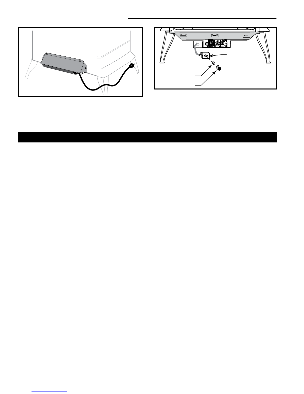
• Insert the switch box shaft through the hole in the
back of the left side of the panel, aligning the locator
pin with the smaller hole in the panel. (Fig. 17)
• Attach the retaining nut to the switch control shaft to
secure it to the plate.
• Attach the control knob to the rheostat shaft.
20306761
13
Page 14
Intrepid® Direct Vent - Rear Vent Gas Heater
Rheostat
Retaining Nut
KT902
Fig. 16 Correct position of fan skirt installation.
• Use the wire tie to secure the fan and rheostat wire
harnesses together to the tubing under the bottom
of the unit.
Venting System Components
Approved Vent System Components
The Intrepid Heater must be vented to the outdoors
through an adjacent exterior wall or through the roof. The
venting system must be comprised of the appropriate
listed venting components specied on this page. These
parts are available from DuraVent Corporation.
See Figure 4 for dimensions relevant to the standard
minimum-vent kits.
DuraVent Components
www.duravent.com
Phone: 1-800-835-4429, Fax: 1-707-446-4740
Minimum Horizontal Vent Kit 46DVA-KHC
Venting Component required for:
Basic Straight Through-the-Wall Installation
Horizontal Termination Cap 46DVA-HRC
Vermont Castings Group Zero Clearance
Sleeve (included) 54623
Firestop 46DVA-WFS
Wall Thimble Cover 46DVA-DC
24” Straight (Maximum length) 46DVA24B
Hardware Package (2 req’d) 56167
NOTE: DuraVent Wall Thimble, 46DVA-WT is not ap-
proved for use with this appliance except in noncombustible masonry walls.
For corner installation add:
45° Elbow, Blk. 46DVA-E45B
Venting Components
90° Elbow, Blk. 46DVA-E90B*
45° Elbow, Blk. 46DVA-E45B
6" Straight, Blk. 46DVA-06B*
9" Straight, Blk. 46DVA-09B
81⁄2" Pipe Extension, Blk 46DVA-08AB*
16" Pipe Extension, Blk 46DVA-16AB
12" Straight 46DVA-12
Rheostat Knob
Fig. 17 Attach rheostat to bracket.
KT903
24" Straight 46DVA-24B*
36" Straight 46DVA-36B
48" Straight 46DVA-48
Square Horizontal Termination Cap 46DVA-HC
Sconce Horizontal Termination Cap 46DVA-HSC
Round Horizontal Termination Cap 46DVA-HRC
Wall Plate 46DVA-DC*
Vinyl Siding Standoff 46DVA-VSS
Snorkel Termination - 14" 46DVA-SNK14
Snorkel Termination - 36" 46DVA-SNK30
Wall Strap 46DVA-WS
Cathedral Ceiling Support Box 46DVA-CS
Storm Collar 46DVA-SC
Firestop Spacer 46DVA-FS
Flashing 0/12 - 6/12 46DVA-F6
Flashing 6/12 - 12/12 46DVA-F12
Wall Thimble 46DVA-WT*
Wall Thimble Cover (Brass) 3PVP-TKV
Wall Firestop 46DVA-WFS
Attic Insulation Shield 46DVA-IS
Co-Linear Vent Adapter 46DVA-GCL
Steel Chimney Conversion Kit
Kit A (6
5
⁄8" - 85⁄8") 46DVA-KCA
Kit B (65⁄8" - 101⁄2") 46DVA-KCB
Kit C (65⁄8" - 13") 46DVA-KCC
Masonry Chimney Conversion Kit 46DVA-KMC
Vertical Termination Cap (High Wind) 46DVA-VCH
Vertical Termination Cap (Low Prole) 46DVA-VC
*Included in Minimum Horizontal Vent Kit 46DVA-KHC
All DuraVent Straight vent pipe sections have a net
length 11⁄2" (37 mm) less than the nominal dimension;
i.e., a 6” (152 mm) Straight pipe section has an effective
length of 41⁄2" (115 mm).
Refer to the DuraVent website for additional components. (www.duravent.com)
14
20306761
Page 15

Intrepid® Direct Vent - Rear Vent Gas Heater
Venting System Assembly
General Information
The Intrepid is approved for installation only with the Dura
Vent components listed on page 14. Follow these and the
vent component instructions exactly.
For U.S. installations: The venting system must conform
with local codes and/or the current National Fuel Gas Code,
ANSI Z223.1/NFPA 54
For Canadian installations: The venting system must
conform to the current CSA B149.1 installation code.
Options
The DuraVent Direct Vent Pro offers a complete line of
component parts for both horizontal and vertical installation. Many items are offered in decorative black as well
as galvanized nish. The galvanized pipe and ttings may
be used for concealed locations such as attics, or spaces
where corrosion is a factor, such as above the rooine.
Decorative black painted sections are recommended for
use on visible interior runs. Decorative brass trim kits are
available for both Wall Thimbles and Ceiling Support Boxes. Snorkel Terminations are available for applications
which may require vertical rise on the building exterior.
Planning Your Installation
There are two basic types of Direct Vent Pro installations:
Horizontal Termination (Figs. 18 and 19)
Vertical Terminations (Fig. 20)
When planning your installation, it will be necessary to
select the proper length of vent pipe for your particular
requirement. For horizontal installations, check these instructions to determine the minimum clearance from the
rear of the appliance to the wall. It is also important to note
the wall thickness. Select the amount of vertical rise desired or required, for “vertical-to-horizontal” installations
(verify that it is within the minimum and maximum limits.
Refer to page 8). To determine the length of vent pipe required for vertical installations, measure the distance from
the appliance ue outlet to the ceiling, the ceiling thickness, the vertical rise in an attic or second story, and allow
for sufcient vent height above the rooine. For multi-story applications, restops are required at each oor/ceiling
level. If an offset is needed in the attic, additional pipe and
elbows will be required.
Figure 18
Zero Clearance Wall Sleeve
Round Ceiling Support /
Wall Thimble Cover
Pipe Section
ST973
Figure 19
Pipe Section
90° Elbow
Pipe Section
Square Horizontal
Termination
Firestop
Square Horizontal
Termination Cap
Zero Clearance
Wall Sleeve
Firestop
Round Ceiling
Support / Wall
Thimble Cover
90° Elbow
20306761
ST974
15
Page 16

Intrepid® Direct Vent - Rear Vent Gas Heater
10"
(254 mm)
10"
(254 mm)
7¹⁄₂" Dia.
(190 mm)
18¹⁄₄"
(464 mm)
to
Center of
Opening
Figure 20
Round Ceiling Support /
Wall thimble
Pipe Section
Vertical High
Wind Termination
Cap (shown)
Storm Collar
Roof
Flashing
Ceiling Firestop
Cathedral
Ceiling Support
Box
90°Elbow
Vent Opening - Combustible Wall
Framing Detail
Vent Opening - Noncombustible Wall
VO584-100b
Fig. 21 Locate vent opening. NOTE: Zero clearance sleeve
is required for combustible wall installations.
3. Install the Wall Firestop/Sleeve assembly into the wall
cutout and fasten the restop to the wall cutout framing
members. (Fig. 23)
10” x 10” (254 x 254 mm)
Wall Opening
Zero Clearance Sleeve
- Seal Around
Firestop
Wall Plate
ST975
Rear Vent
Use components listed on page 14 under ‘Basic Straight
through-the-Wall Installation’ for an installation where the
heater is parallel to the wall and the vent system extends
straight back through that wall.
1. Locate the vent opening on the wall. Refer to Figures
20 & 21 to determine the top of the opening centerline.
It may be necessary to rst position the stove and measure to nd the hole location. Depending on whether the
wall is made of combustible materials, cut the opening to
the size shown in Figure 21. Combustible wall openings
must be framed as shown in Figure 21.
2. Measure the wall thickness and cut the zero clearance
sleeve sections to proper length (MAXIMUM 12”).
Assemble the sleeve with the #8 sheet metal screws
supplied. Attach the restop plate to the sleeve end with
the holes. (Fig. 22) NOTE: The zero clearance sleeve
is required in combustible walls only.
16
Seal Around
Terminal
ST950
All Components Must
Remain Concentric
Fig. 22 Intrepid minimum horizontal rear vent installation.
12”
(305mm)
Max. Length
Firestop
Sleeve
#8 Sheet Metal
Screws
ZCS103
Fig. 23 Assemble the wall sleeve and restop.
20306761
Page 17

4. Slip the wall cover over the interior end of the horizontal
pipe and install into the zero clearance sleeve. Seal the
joint inside the wall plate if needed to keep cold air from
being drawn into the home.
5. Install the vent terminal. (Fig. 22) Guide the inner and
outer vent termination collars into the adjacent pipes.
Double check that the vent pipes overlap the collars by
2”. Fasten the termination to the outside wall with the
screws provided, and caulk the joint with weatherproof
sealant.
6. Use wall straps to support vertical pipe runs at 4’ (1219
mm) intervals.
Horizontal Installation
Step 1. Set the gas appliance in its desired location.
Check to determine if wall studs or roof rafters are in the
way once the venting system is attached. If this is the
case, you may want to adjust the location of the appliance.
Step 2. DirectVent Pro pipe and ttings are designed with
special twist-lock connections. To connect the venting
system to the appliance ue outlet, a twist-lock appliance
adaptor is built into the appliance at the factory. Assemble
the desired combinations of black pipe sections and elbows to the appliance adapter with pipe seams oriented
towards the wall or oor, as much out of view as possible.
(Fig. 24)
Figure 24
Intrepid® Direct Vent - Rear Vent Gas Heater
Figure 25
ST977
2. Horizontal vent runs of vent pipe must be supported
to prevent any downward sags. Horizontal pipe sections should be supported at least every 4’ (1.2 m).
Wall straps can be used for this purpose. Alternatively,
plumbers tape or other suitable noncombustible material can be used to support the vent pipe.
3. DirectVent Pro venting requires no sealant.
Step 3. With the appliance adapter and pipe section attached, slide the stove into its correct location. Mark the
wall for a square hole that measures 10” x 10” (254 x
254 mm). The centerline of the pipe should line up with
the center of the square hole. (Fig. 26) Cut and frame
the square hole in the exterior wall where the vent will be
terminated. If the wall being penetrated is constructed of
noncombustible material only, i.e. masonry block, brick or
concrete only, a hole with zero clearance is acceptable.
NOTES:
ST976
NOTES:
1. Twist-lock procedure: Line up locking lugs on male
and female ends of pipe sections. Insert the male end
of pipe into the female end until the locking lugs are
covered. Twist the female end clockwise an eighth of a
turn to lock sections together. (Fig. 25) Screws are not
required to secure the joint, but are acceptable provided they do not penetrate the inner wall of the vent
pipe.
Center of
Hole
C
L
Figure 26
ST978
1. The horizontal run of venting must be level, or have a
1/4” (6 mm) rise for every 1’ (305 mm) of run toward
the termination. Never allow the vent to run downward.
A downward slope can trap heat and become a pos-
sible re hazard.
20306761
17
Page 18

Intrepid® Direct Vent - Rear Vent Gas Heater
2. The location of the horizontal vent termination on an
exterior wall must meet all local and national building
codes, and must not be easily blocked or obstructed.
Refer to Pages 10 and 11 for proper Termination Clearances.
For installations requiring a vertical rise on the exterior
of the building, 14” (356 mm) and 36” (914 mm) tall snorkel terminations are available. (Fig. 27) Follow the same
installation procedures as used for standard horizontal
terminations. If the snorkel termination must be installed
below grade level, (i.e. basement application), proper
drainage must be provided to prevent water from entering the snorkel termination. (Fig. 28) Do not attempt to
enclose the snorkel within the wall or any other type of
enclosure.
Figure 27
Snorkel
12” (305 mm)
Minimum
(102 mm)
4”
NOTES:
1. The four (4) wood
screws provided
should be replaced
Figure 29
Wood
Screws
with appropriate
fasteners for use on
brick, block, concrete or other types
of sidings.
2. For buildings with
vinyl siding or stucco, another component must be used
between the horizontal termination
cap and the wall
HOT
surface. The vinyl
siding standoff pre-
ST981
vents excessive
heat from possibly melting the vinyl siding material. Vinyl siding standoffs are not required with snorkels. For
vinyl wall installations a 4-piece vinyl siding standoff
should be assembled and installed between the horizontal termination cap and the exterior wall. (Fig. 30)
The vinyl should be cut away to the outer edges of the
assembled standoff.
ST979
Snorkel
Figure 28
12” (305 mm)
Minimum
4” (102 mm)
ST980
Step 4. Position the horizontal termination cap in the center of the square framed hole, and attach to the exterior
wall with the four (4) wood screws provided. Before attaching the vent termination cap to the exterior wall, run
a bead of non-hardening silicone sealant around the
outside edges to make a seal between the cap and the
wall. The arrow on the vent cap should be pointing up.
Ensure proper clearances to combustible materials are
maintained. (Fig. 29)
Figure 30
Cut Back
Siding
ST982
Sconce
Cap
4 pc. Vinyl Siding
Standoff
Wood Screws
(4 Req.)
Round
Cap
Wood Screw
IMPORTANT: You must attach the four (4) pieces of the
new vinyl siding standoff to the horizontal termination cap
in specic order to ensure a weather tight t. Loosely assemble the four parts, in order, around the base of the hor-
izontal termination cap. Place the rst of four pieces along
the upper edge of the cap, then using two (2) screws per
side, secure each piece to the pre-drilled holes along both
sides of the cap, nally, attach the nal piece to the bottom edge of the cap. Tighten all screws and mount cap,
with all four (4) pieces attached, directly onto the wall with
the four (4) 21⁄2" (64 mm) screws provided. (Fig. 30)
18
20306761
Page 19

Intrepid® Direct Vent - Rear Vent Gas Heater
3. When penetrating through stucco wall, install the
counter ashing. The counter ashing allows stucco,
or other materials, to be nished directly to the sides
of the termination cap. First attach the counter ash-
ing to the base of the horizontal termination cap with
the small screws provided, then mount entire assembly onto the wall with the four (4) 2
1
⁄2" (64 mm) wood
screws provided.
4. If the optional copper version of the horizontal termination cap is installed, use an appropriate noncombustible material to avoid direct contact between the galvanized and copper metals to prevent possible galvanic
reaction.
Step 5. Before connecting your horizontal pipe sections
to the horizontal termination cap, slide the wall thimble
cover over the pipe section nearest the interior side of
wall. (Fig. 31)
Step 6. Slide the appliance and vent assembly towards
the wall, carefully inserting the pipe section into the cap
assembly. It is important the pipe section extends into the
back of the termination cap with a minimum overlap of
11⁄4" (32 mm). Use the two (2) sheet metal screws pro-
vided to secure the pipe section to the back of the termination cap. The wall thimble cover will cover the screw
heads. (Fig. 31)
Figure 31
Zero Clearance
Wall Sleeve
Sheet Metal
Screws
ST983
Wall Thimble Cover
Firestop
Step 7. Slide the wall thimble cover up to the wall surface
and attach to the wall with screws provided. (Fig. 32) Apply optional decorative brass trim to wall thimble cover if
desired.
Vertical Installation
Step 1. Check these installation instructions for required
clearances (air spaces) to combustibles when passing
through ceilings, walls, roofs, enclosures, attic rafters or
other nearby combustible surfaces. Do not pack air spaces with insulation. Check these instructions for maximum
vertical rise of the venting system and any maximum horizontal offset limitations.
Figure 32
Wood Screws
ST984
Step 2. Set the gas appliance
Figure 33
in the desire location. Drop a
plumb bob down from the ceiling to the position of the ap-
pliance ue exit, and mark the
location where the vent will
penetrate the ceiling. Drill a
small hole at this point. Next,
drop a plumb bob from the roof
to the hole previously drilled in
Mark Location
Mark and Drill
the ceiling, and mark the spot
where the vent will penetrate
the roof. (Fig. 33) Determine if
ceiling joists, roof rafters, framing or other materials will obstruct the venting system. You
Plumb Bob
may wish to relocate the appliance or to offset, to avoid cutting load-bearing members.
Step 3. To install the round ceiling support/wall thimble cover
in a at ceiling, cut a 10” x 10”
(254 x 254 mm) square hole in
the ceiling (unless otherwise
specied) centered on the hole
ST985
drilled in Step 2. Frame the hole
as shown in Figure 34.
Step 4. If the twist-lock appliance adapter has not been
installed on the stove, do so now.
Step 5. Assemble the desired pipe sections and elbows
necessary to reach from the appliance adapter up through
the round ceiling cover or support box. Ensure that all
pipe and elbow connections are in their fully twist-locked
position.
Step 6. Cut a hole in the roof centered on the small drill
hole placed in the roof in Step 2. The opening should be
of sufcient size to meet the minimum requirements for
clearance to combustibles, as specied. Continue to as-
20306761
19
Page 20

Intrepid® Direct Vent - Rear Vent Gas Heater
Figure 34
semble pipe sections
and elbows as necessary to reach up through
the roof line. Galvanized
pipe and elbows may
be utilized in the attic,
Ceiling
Joists
Cut
and
Frame
as well as above the
rooine. The galvanized
nish is desirable above
the rooine, due to high-
er corrosion resistance.
Decorative
Ceiling Support
Cover
1
1
⁄2" Wood
Screws
Figure 35
ST986
ST987
Figure 36
Pipe
Extension
Pipe
Section
NOTES:
1. If exact lengths or distances must be met between elbow offsets or
Wall Strap
/ Plumbers
Tape
elsewhere, use the pipe
extensions to adjust onto
standard pipe sections.
(Fig. 35)
2. If an offset is necessary
in the attic to avoid ob-
45°
Elbow
45°
Elbow
structions, it is important
to support the vent pipe in
order to avoid excessive
stress on the elbows. Wall
ST988
straps or plumber tape
may be used for this purpose. (Fig. 36)
3. Wherever possible, use 45° elbows instead of 90° el-
bows. The 45° elbow offers less restriction to the ow
of ue gases and intake air.
Step 7. Slip the roof ashing over the pipe section(s) pro-
truding through the roof. Use a non-hardening sealant be-
tween the roof ashing and the roong to prevent water
leakage. Secure the base of the roof ashing to the roof
with roong nails. Ensure the roong material overlaps
the top edge of the roof ashing. (Fig. 38) Verify that you
have at least the minimum clearances to combustibles at
the rooine and in the attic.
Step 8. Continue to add pipe sections until the height of
the system (before adding the cap) meets the minimum
building codes requirements as described
in Table 2, Figure 37.
Note that for steep
Figure 37
Dimension ‘H’
from Table 2
H
roof pitches, the vent
height must be increased. In high wind
conditions, nearby
trees, adjoining rooines, steep pitched
roofs and other similar
ST989
factors can result in
Table 2
Roof Pitch Minimum Height
Flat 7/12 1’ (914 mm)
Over 7/12 to 8/12 1’6” (457 mm)
Over 8/12 to 9/12 2’ (610 mm)
Over 912 to 10/12 2’6” (762 mm)
Over 10/12 to 11/12 3’3” (990 mm)
Over 11/12 to 12/12 4’ (1.2 m)
Over 12/12 to 14/12 5’ (1.5 m)
Over 14/12 to 16/12 6’ (1.8 m)
Over 16/12 to 18/12 7’ (2.1 m)
Over 18/12 to 20/12 7’3” (2.3 m)
Over 20/12 to 21/12 8’ (2.4 m)
poor draft, or down drafting. In these cases, increasing
the vent height or switching to the high wind termination
cap may help to solve the problem.
Step 9. Slip the storm collar over the pipe section, and
push it down to the top of the roof ashing. (Fig. 38) Use
non-hardening sealant between the storm collar and the
pipe section
Step 10. Holding the bottom of the termination cap only,
twist lock the cap onto the last pipe section protruding
above the rooine.
NOTES:
1. For multi-story vertical installations, a ceiling restop
is required at the second oor, and any subsequent
oors. (Fig. 39) Cut and frame a 9” x 9” (229 x 229 mm)
square opening for installation of the ceiling restop.
2. If vent passes through any occupied areas above the
rst oor, including closets and storage spaces, it must
be enclosed. The enclosure may be framed and covered with sheet rock with standard construction materials, but required clearances to combustibles must be
maintained. Consult these installation instructions for
the minimum allowable clearances between the out-
20
20306761
Page 21

Intrepid® Direct Vent - Rear Vent Gas Heater
High Wind Vertical
Termination
Storm Collar
Roof Flashing
Optional
Low Prole
Termination
Cap
Secure Flashing
with Non-hardening Sealant and
Roong Nails
Figure 38
side of the vent pipe
and the combustible
surfaces of the en-
ST990
closure. Do not ll required air spaces with insulation.
3. If venting system passes through an attic space an attic insulation shield must be installed to prevent contact between pipe sections and the insulation. Nail the
base to oor of attic and adjust shield for appropriate
insulation level, then attach the collar at the top of assembly. (Fig. 39) For vaulted ceilings, the attic insulation shield cannot be installed. To prevent building
insulation and other debris from entering the support
box or contacting the pipe, a chase enclosure can be
constructed around the support box. Ensure proper
clearance to combustibles are maintained.
Cathedral Ceiling Installation
Step 1. Follow installation Step 1 and 2 under Vertical
Termination.
Step 2. Using the plumb bob, mark the centerline of the
venting system on the ceiling and drill a small hole through
the ceiling and roof at this point. From the roof, locate the
drill hole and mark the outline of the Cathedral Ceiling
Support Box.
Step 3. Remove shingles or other roof covering as necessary to cut the rectangular hole for the support box. Cut
the hole 1/8” (3 mm) larger than the support box outline.
Step 4. Lower the support box through the hole in the roof
until each side of the bottom of the support box protrudes
at least 2” (51 mm) below the ceiling. (Fig. 40) Align the
support box both vertically and horizontally with a level.
Figure 39
Required
Clearance
Figure 40
Cathedral Ceiling
Support Box
Attic
Insulation Shield
ST991
Level
ST992
Nails
Minimum
Clearance
Minimum
Clearance
2” Min. Below
Finished Ceiling
Cut Hole 1/8”
Larger than Support Box
Temporarily tack the support box in place through the inside walls and into the roof sheathing.
Step 5. Using tin snips, cut the support box from the top
corners down to the rooine, and fold the resulting aps
over the roof sheathing. The aps may be trimmed as
needed. (Fig. 41) Before nailing it to the roof, run a bead
of non-hardening sealant around the support box to make
a seal between the support box and the roof. Clean out
any combustible material from inside the support box.
Step 6. Follow Steps 4 and 5 of the Vertical Installation
instructions.
Step 7. Place the support clamp (provided with the support box) inside the support box (at the bottom), and secure to the pipe section. The clamp allows the support
box to support the weight of the pipe sections. Continue to
add pipe sections until you are above the rooine.
20306761
21
Page 22

Intrepid® Direct Vent - Rear Vent Gas Heater
Figure 41
ST993
Step 8. Follow Steps 7 through 10 of the Vertical Installation instructions
Step 9. Install the black trim collar around the outside of
the Cathedral ceiling support box. The two pieces of the
trim collar slide over one another to allow for easy adjustment around the support box. Using the six (6) screws
provided, secure the four corners and the overlapping
sections of the trim collar to the underside of ceiling. You
may want to predrill the holes for the overlapped sections
for ease of installation. (Fig. 42)
Figure 42
Overlap
Cathedral Ceiling Support Box
ST994
Ceiling Trim
Screws
General Maintenance
Conduct an inspection of the venting system annually.
Recommended areas to inspect are as follows:
1. Check areas of the venting system which are exposed
to the elements for corrosion. These will appear as rust
spots or streaks, and in extreme cases, holes. These
components should be immediately replaced.
2. Remove the vertical terminations cap and shine a
ashlight down the vent. Remove any bird nests, or
other foreign material.
3. Check for evidence of excessive condensation, such
as water droplets forming in the inner liner, and subsequently dripping out at joints. Continuous condensate
can cause corrosion of caps, pipe and ttings. It may
be caused by having excessive lateral runs, too many
elbow and exterior portions of the system being exposed to cold weather.
4. Inspect joints to verify that no pipe sections or ttings
have been disturbed or loosened. Also check mechanical supports such as wall straps or plumbers tape for
rigidity.
Supplemental Canadian Instructions
When installing DirectVent Pro on appliances in Canada,
a 2-piece decorative wall thimble is required in order to
comply with IR #41. (Fig. 18 and 20) Install galvanized
exterior wall thimble plate on exterior of building and black
decorative wall thimble plate on the interior side of wall.
Install wall thimble centered through a square framed
opening in wall. Be sure to maintain all minimum clearances. When installing DirectVent Pro vertically through
oors, a ceiling restop is required at every oor/ceiling
level.
Vertical Through Existing Chimney
The heater must be vented to the outdoors through an ex-
isting masonry or prefabricated replace chimney system
through the roof.
The heater is approved to be vented to the outdoors through
any solid-fuel replace chimney that has been constructed
or installed in accordance with the national, Provincial/State
and local building codes and is constructed of noncombustible materials. For Venting Requirements, refer to page
10. Refer to Venting Components on page 14.
Converting a Class-A Metal Chimney or Masonry Chimney to a Direct Vent System
Application
These instructions apply to the DuraVent Direct Vent Conversion kits for factory-built Class-A metal chimneys and
masonry chimneys. These venting systems, in combination
with the gas appliance, have been tested and listed by a
major testing agency such as UL, AGA, Omni or Warnock
Hersey. Check the manufacturer’s rating plate and instruc-
tion manual to conrm that a DuraVent Direct Vent Chimney
Conversion system is approved for use on the brand name
appliance you have selected.
IMPORTANT
Read all instructions carefully before starting the installation. Failure to follow these instructions may create a
re or other safety hazard, and will void the warranty.
Be sure to check the appliance manufacturer’s installation instructions for specic venting and clearance
to combustible requirements, which may vary from
one appliance to another.
22
20306761
Page 23

Intrepid® Direct Vent - Rear Vent Gas Heater
Use Conversion Kit A (#0931) for
the following chimney:
6” ID Metalbestos
6” ID Security Chimney
6” ID Jackes - Evans
6” ID Hart & Cooley
6” ID Pro Jet
Use Conversion Kit B (#0932) for
the following chimney:
6” ID DuraVent
7” & 8” ID Metalbestos
7” ID Security Chimney
7” & 8” ID Jackes - Evans
7” & 8” ID Hart & Cooley
7” & 8” ID Pro Jet
6” & 7” ID Metal -Fab
6” & 7” ID American Metals
Use Conversion Kit C (#0933)
for the following chimney:
7” & 8” ID DuraVent
8” ID Air Jet
8” ID Metal Fab
8” ID American Metals
0909B
ST955
Installation Precautions
The DuraVent Direct Vent System is an engineered product
that has been designed and tested for use with an approved
list of direct vent gas appliances. The DuraVent warranty will
be voided, and serious re, health or other safety hazards
may result from any of the following actions:
to factory-built metal ceiling-supported type systems
and masonry through-the-wall type systems. NOTE:
You cannot install a Conversion Kit in a through-thewall type factory-built metal chimney.
General Installation
Two different types of direct vent conversion systems are
described here. One is through an existing factory-built
metal chimney going through the ceiling. The other is
through the wall of an existing masonry chimney. Follow
the appropriate directions for your situation.
A typical direct vent conversion of a factory-built metal
chimney is shown in Figure 43. The concept of the direct
vent conversion is to connect an adapter to an Underwrit-
ers Laboratories listed 4” diameter aluminum ex pipe
(DuraVent’s DuraFlex is an example of a UL listed ex
pipe). The ex is then passed down through the center of
the existing metal chimney system. Three sizes of termi-
nation caps are available which should t most sizes and
makes of metal chimney systems. The Retro Connector
(909B) is then attached to the bottom of the ex pipe. Both
the cap adapter and retro connector are attached to the
existing chimney with sheet metal screws. The appliance
is then connected to the chimney with appropriate black
direct vent pipe and an adjustable length section.
A typical conversion of an existing masonry chimney is
shown in Figure 45. For installation through the wall of
an existing masonry chimney, a cap adapter (985K) and
ashing are used at the top of the masonry chimney. The 4”
aluminum liner is connected to the adapter and is passed
down the chimney and out through the masonry wall. This
is attached to the retro connector (909B) which is in turn,
attached to the masonry wall and is then connected to the
direct vent pipe leading to the appliance.
• Installation of any damaged Direct Vent compo-
nent.
• Unauthorized modication of the Direct Vent Sys-
tem.
• Installation of any component part not manufactured
or approved by DuraVent.
• Installation other than as instructed by DuraVent and
the appliance manufacturer.
Consult your local building codes before beginning the
installation. Have the existing installation inspected by a
qualied chimney sweep or professional installer, prior to
converting to direct vent. The existing chimney system must
be in serviceable condition, and functionally sound. The
direct vent conversion described herein applies only
20306761
23
Page 24

Intrepid® Direct Vent - Rear Vent Gas Heater
ST956
metal chim conv
7/07
Figure 43
Converting a Factory-Built Metal Chimney
Termination Cap
Top Adapter
0985K, 0986K or 0987K
Existing Metal
Chimney System
4” Aluminum Flex Pipe
Figure 44
Co-Linear Insert
Vertical
Termination
Cap
Chimney Liner
Termination Kit
3” Flex
Retro Connector
0909B
Co-Axial to
Co-Linear
Connector
Any Black Direct
Vent Pipe Plus an
Adjustable Length
to Make a Proper
Connector
ST995
ST956
24
20306761
Page 25

Intrepid® Direct Vent - Rear Vent Gas Heater
Figure 45
Converting a Masonry Chimney
Termination
Cap
Top Adapter
Flashing
4” Flex Liner
Installation Instructions for Converting a Factory-Built Metal Chimney
1. Remove the existing chimney cap.
2. Measure the distance from the top end of the chimney
to the bottom of the ceiling support box, add 3” to this
measurement and cut a section of 4” ex pipe to that
length (the ex should already be extended to its nominal
length).
3. Connect the end of the ex pipe section to the underside
of the cap adapter you have selected using three (3)
sheet metal screws. (Fig. 46)
Top
Adapter
Sheet
Metal
Screws
Retro Connector
Black Direct
Vent Pipe
ST961
Flex
Figure 46
ST957
Pipe
4. Pass the ex pipe down through the center of the chimney system, and center the adapter on the top of the
chimney pipe. Drill four (4) 1/8” diameter holes through
the adapter and into the chimney top. Insure that you are
in fact, drilling into the metal on the chimney. Twist-lock
the termination cap (980, 991 or 930) onto the adapter.
(Figs. 47 and 48)
Figure 48
Figure 47
5. Pull the ex pipe down through the ceiling support box,
Termination
Cap
Sheet
Metal
Screws
Drill
Four (4)
1/8” Diameter
Holes
until it protrudes approximately 3” (76 mm). Connect
the ex pipe to the retro connector by slipping it into
3
⁄4"(121 mm) diameter sleeve on the top side of
the 4
the connector. Use three (3) sheet metal screws to
assemble these two parts.
20306761
25
Page 26

Intrepid® Direct Vent - Rear Vent Gas Heater
Sheet Metal
Screws (3)
Existing Ceiling
Support Box
ST960
Sheet Metal
Screws (3)
Figure 49
6. Push the ex pipe back up into the ceiling support box,
center the retro connector and attach it to the support
box or decorative sleeve for double wall solid packed
pipe, with the sheet metal screws furnished. The holes
in the retro connector are pre-punched. (Fig. 49)
7. The connection between the appliance and the retro
connector may be completed with sections of black
direct vent pipe, together with an adjustable length.
Installation Instructions for Converting a Masonry Chimney
IMPORTANT: The existing masonry ue opening need to
have an area of at least 35 square inches (226 square mm)
to insure proper intake/exhaust ow.
1. Before cutting any holes, assemble the desired sections
of black direct vent pipe to determine the center of the
masonry penetration.
2. Once the center point of the penetration has been determined, cut a 6” (152 mm) diameter hole in the masonry.
Be careful, if the hole is too large, the retro connector
might not mount properly. If the hole is too small, then
the appliance might starve for intake air. If there is a
frame wall in front of the masonry wall, cut and frame a
10” (254 mm) clear square opening in the wall (centered
around the 6” (152 mm) masonry opening). If there is
sheet rock only (no studs) in front of the masonry, the
10” (254 mm) clear opening is still needed, but does not
need to be framed. This allows the retro connector to
mount directly on the masonry and provide clearance
to the combustibles. (Fig. 54)
3. Secure the ashing (705C) to the top of the masonry
chimney using a bead of non-hardening sealant-adhe-
sive. If the ashing is larger than the top of the chimney,
then cut and fold ashing as needed to t chimney. (Fig.
50)
4. To determine the length of ex required, measure from 3”
(76 mm) above the top of the ashing down to the level
of the opening. Add to this measurement the distance
from the center of the chimney to out through the wall.
Cut a piece of 4” (102 mm) ex to this length (the ex
should already be extended to its nominal length).
5. Connect the 4” ex liner to the cap adapter (985K) using
three sheet metal screws. (Fig. 46)
Cut & Bend
Flashing as
Needed to Fit
Chimney
Figure 50
Sealant Adhesive
6. Feed the 4” ex liner through the ashing into the chim-
ney. Continue to feed the liner out through the opening
in the masonry wall.
7. Secure the cap adapter to the ashing. Use three (3)
sheet metal screws through the side of the adapter
into the ange on the ashing as shown in Figure 51.
Twist-lock the termination cap (980,991, 930) on to the
cap adapter.
High Wind
Termination Cap
Standard
Termination
Cap
Top Adapter
Sheet
Metal
Screws (3)
Flashing
ST963
Figure 51
8. Attach the ex to the retro connector. Use three sheet
metal screws to attach the ex liner to the connector.
(Fig. 52) Mount the retro connector to the masonry wall
using masonry bolts. Re-drill larger holes on connector
as needed. Be careful to insure that the connector is
centered in the opening and the mounting holes line up
with the masonry wall.
9. Slide the wall thimble cover (940) over the retro connector
and secure the with masonry bolts as shown in Figure
53. If you have a framed wall in front of the masonry,
use wood screws to mount the wall thimble cover to the
framed wall, over the retro connector and the 10” (254
mm) square framed opening as shown in Figure 54. If
needed, add a section of direct vent pipe to the retro
connector in order to extend through the opening in the
wall thimble cover.
26
20306761
Page 27

Intrepid® Direct Vent - Rear Vent Gas Heater
10. The connection between the appliance and the retro
connector may be completed with the section of black
direct vent pipe, together with an adjustable length pipe
section.
6” Diameter
Opening in
Masonry Wall
Retro
Connector
Masonry Bolts (3)
(Not included)
Figure 52
Retro Connector
Wall Thimble Cover
Masonry Bolts (4)
(Not included)
Figure 53
Stud Wall
10” X 10” Framed
Opening in Wall
Retro Connector
Wall Thimble
Cover
ST964
ST965
Connect the Gas Supply Line
Check the rating plate attached by a steel cable to the
rebox, to conrm that you have the appropriate rebox
for the type of fuel to be used. The Intrepid may be converted from one gas to another using the appropriate Fuel
Conversion Kit listed on page 42.
CAUTION
This appliance should only be connected
by a qualified gas technician. Test to
conrm manifold pressures as specied
below.
The Intrepid Heater and the individual shutoff valves
must be disconnected from the gas supply piping
during any pressure testing of that system at test
pressures in excess of 1/2 psig (3.5 kPa).
The Intrepid Heater must be isolated from the gas
supply piping system by closing the individual
manual shutoff valve during any pressure testing
of the gas supply piping system at test pressure
equal to or less than 1/2 psig.
There must be a gas shutoff between the stove and
the supply.
In order to connect Natural Gas, use a tting with
3/8” NPT nipple on the valve side and 1/2” natural
gas supply line with a minimum input of 21,000
BTUs at a minimum inlet pressure of 5.5” w.c.
In order to connect Propane, use a tting with 3/8”
NPT nipple on the valve side and 1/2” propane gas
supply line with a minimum input of 21,000 BTUs
at a minimum inlet pressure of 11.0” w.c.
In the U.S.: Gas connection should be made in accordance
with current National Fuel Gas Code, ANSI Z223.1/NFPA
54. Since some municipalities have additional local codes,
be sure to consult your local authority.
In Canada: consult the local authority and CSA-B149.1
installation code.
Connect the gas supply and test for leaks. Use a mild soap
and water solution applied with a brush no larger than 1”
(25 mm). Never apply soap and water solution with a spray
bottle. Do not use an open ame for leak testing.
Masonry
Chimney
Masonry Bolts
(4)
(Not included)
Figure 54
20306761
ST966
27
Page 28

Intrepid® Direct Vent - Rear Vent Gas Heater
PILOT
ADJ
TP
TH
TPTH
INTREPID
Burner Information
The appliance must only use the gas specied on the
rating plate, unless converted using a Vermont Castings
Fuel Conversion Kit. Refer to page 42 for correct Fuel
Conversion Kit for your stove model.
Coversion instructions are provided with each kit and on
page 34 of this manual.
THIS APPLIANCE SHOULD BE CONNECTED TO THE
GAS SUPPLY ONLY BY A QUALIFIED GAS SERVICE
TECHNICIAN. FOLLOW ALL LOCAL CODES.
THERE MUST BE A GAS SHUT-OFF BETWEEN THE
STOVE AND THE SUPPLY.
Complete the Assembly
• Open the swiveling latches (cams) on the top left and
right corners of the glass frame.
• Position the glass and frame against the rebox by
placing the bottom edge on the brackets on the bottom
face of the rebox.
• Swing the assembly against the rebox, and close the
latches rmly against the pins protruding from the rebox
top.
Install ON/OFF Switch
The switch assembly parts are found in the parts bag.
1. Apply wiring harness to the ON/OFF switch terminals
then insert into cut out on switch housing. The ON/OFF
switch will ‘snap’ into the cutout. (Fig. 55)
2. Run wires through cut out in side of shroud, under bottom of rear shroud to valve.
3. Using supplied #10 x 1/2” screws, attach switch housing
over cut out opening in rear shroud.
4. Attach wires to valve terminals. (Fig. 56)
ST228
Fig. 56 Attach switch wires to valve.
Install the Front Plate
Grasp the Front Plate and lift it into position, engaging the
two steel tabs at the upper corners behind the adjacent
bosses in the Side Plates. (Fig. 57) Seat the Front against
the Sides so that the tabs at the bottom lip engage with the
notches in the edge of the stove base.
When properly installed, the bottom of the Front Plate
cannot be pulled away from the sides without also lifting
it up.
If you are installing optional Warming Shelves, do so now,
according to the instructions supplied with that kit.
Bottom Tabs Engage
Notch in Base
Fig. 57 Install stove front.
ST967
Thermostat Connection
(Optional) R Models Only
Wire
Harness
Switch Assembly
Fig. 55 Attach switch assembly to rear shroud.
Screw
28
ST1120
Use only a thermostat rated for 500 - 750 millivolts.
Check the table below for the appropriate gauge thermostat wire to use for the length of lead required in your
installation.
Thermostat
Wire / Gauge Maximum Run
18 40 feet
20 25 feet
22 16 feet
1. Install the wall thermostat in the desired location and run
the wires to the stove location. Terminate these leads
with 1/4” female connectors.
2. Connect the thermostat wires to the valve. (Fig. 56)
This completes assembly of the Intrepid stove.
20306761
Page 29

Install the Log Set
Remove the logs from their packaging and inspect each
piece for damage. DO NOT INSTALL DAMAGED LOGS.
CAUTION: Before installation, inspect ember bed burner
for damage. Do not use ember bed if damaged or cracked.
NOTE: Small, shallow surface cracks are acceptable.
1. Install the rear log by matching the notch on the bottom
left of the log on the raised notch on back left side of the
ember bed. Cutout on bottom right side is clearance for
pilot assembly. (Fig. 58) Gently push right side of log
back until it contacts thermopile on pilot assembly.
Rear Log
Intrepid® Direct Vent - Rear Vent Gas Heater
Left Log
Right
Log
Figure 60
4. Install top log by mating hole on bottom of log with
locating pin on top right side of rear log. (Fig. 61) Position log so it is angled down toward the area where the
front two logs meet.
Figure 58
2. Place the left front log on the pin locator on ember bed.
Position the log over the air inlet hole and on notched
out portion of ember bed. (Fig. 60)
3. Place front right log on ember bed by mating notch on
bottom of log with raised notch on ember bed. Position
over the air inlet hole and on notched out portion of
ember bed. (Fig. 60)
Raised Notch
Pin
Pilot Assembly
Raised
Notch
Left Log
Figure 61
Ember Bed
Back Log
Top Log
Right Log
Figure 59
20306761
29
Page 30

Intrepid® Direct Vent - Rear Vent Gas Heater
CERTIFIED
SAFETY BARRIER
DANGER
HOT GLASS WILL
CAUSE BURNS.
Safety Barrier Installation Instructions
NOTE: A barrier designed to reduce the risk of burns
from the hot viewing glass is provided with this
appliance and shall be installed for the protection of
children and other at risk individuals. If the barrier
becomes damaged, the barrier shall be replaced with
the manufacturer's barrier for this appliance.* Any
safety screen, guard, or barrier removed for servicing
the appliance must be replaced prior to operating the
appliance.
* See parts list for model number.
The safety barrier has been designed to work with the
doors open or closed.
1. Remove screen from packaging.
2. Align screen on stove front and adjust spring ngers as needed. Press into place until spring ngers
engage. Figure 62
3. Press the screen against the stove snapping the two
spring ngers until the screen ts securely in place.
NOTICE: It is the responsibility of the installer to ensure
the barrier is afxed to the stove at the time of installation. The barrier is designed to be installed with the
doors open or closed.
DO NOT TOUCH GLASS
UNTIL COOLED.
NEVER ALLOW CHILDREN
TO TOUCH GLASS.
A barrier designed to reduce the risk of burns from the hot
viewing glass is provided with this appliance and shall
be installed for the protection of children and
other at risk individuals.
20306543
WARNING: The safety screen barrier
must be installed after the glass front is
in place. It is NOT a replacement for the
glass and the unit must NOT be operated without the glass in place.
Adjustable spring
ngers
Figure 62 Safety Barrier Installation
30
20306761
Page 31

Operation
H
I
L
O
O
F
F
O
N
O
F
F
E A
P
I
L
O
T
THTP
TP
TH
L
O
H
I
Turn
counterclockwise
to increase
flame height
Turn clockwise
to decrease
flame height
Intrepid® Direct Vent - Rear Vent Gas Heater
The Intrepid is operated with the operable door front plate
in place with the doors open or closed. To open the front
doors, pull either door toward you.
Your First Fire
Read these instructions carefully and familiarize yourself
with the burner controls shown in Figure 63. Locate the
pilot assembly, Figure 64. Follow the lighting instructions
on exactly.
During the rst re, it is not unusual to smell some odor
associated with new logs, paint and metal being heated.
Odors should dissipate within a few hours. You can open
a window to provide fresh air to alleviate the condition.
Inlet Pressure Tap
Manifold Pressure Tap
Pilot Adjustment
Screw
Fig. 63 NOVA SIT valve control.
Regulator
Control Knob
Gas Control
Knob
ST941
Flame & Temperature Adjustment
For stoves equipped with HI/LO valves, ame adjustment
is accomplished by rotating the HI/LO adjustment knob
located near the center of the gas control valve. (Fig. 65)
Flame Characteristics
It is important to periodically perform a visual check of the
pilot and the burner ames. Compare them to Figure 66. If
any of the ames appear abnormal call a service person.
Fig. 65 Flame adjustment knob for SIT valve.
PSE Pilot
SIT Pilot
Pilot Assembly
Fig. 64 Pilot Assembly location.
Pilot and Burner Inspection
Each time you light your heater check that the pilot ame
and burner ame pattern are as shown in Figure 66. If
ame patterns are incorrect, turn the heater off. Contact
your dealer or a qualied gas technician for assistance.
Do not operate the heater until the pilot ame is correct.
Follow regular maintenance procedures as described on
page 37.
20306761
Fig. 66 Correct pilot and burner ame patterns.
Extension Knobs
On/Off and Hi/Lo control knob extensions have been in-
cluded in the nish bag. These may be installed on the
appropriate knob by aligning the notch on the existing
knob (Fig. 63) with the tab on the inside of the extension
knob (Fig. 67) Push the extension knob as far as it will go
onto the existing knob.
Tab - align with notch
Fig. 67 Extension knob.
on existing knob
31
Page 32

Intrepid® Direct Vent - Rear Vent Gas Heater
PILOT
ON
OFF
ON
P
I
L
O
T
O
F
F
O
F
F
3/8" - 1/2"
Lighting and Operating Instructions
FOR YOUR SAFETY READ BEFORE LIGHTING
WARNING:If you do not follow these instructions exactly, a re or explosion
may result causing property damage, personal injury or loss of life.
A. This heater has a pilot which must be lit manually.
When lighting the pilot follow these instructions exactly.
B. BEFORE LIGHTING smell all around the heater area
for gas. Be sure to smell next to the oor because
some gas is heavier than air and will settle on the
oor.
WHAT TO DO IF YOU SMELL GAS
• Do not try to light any replace
• Do not touch any electric switch
• Do not use any phone in your building
• Immediately call your gas supplier from a neighbor’s
phone. Follow the gas supplier’s instructions.
Lighting Instructions
1. STOP! Read the safety information above.
2. Turn off all electrical power to the replace.
3. Turn the On/Off switch to “OFF” position, set the
remote to OFF or set thermostat to lowest level.
4. Open control access panel.
5. Push in gas control knob slightly and turn clockwise
to “OFF”.
6. Remove glass door before lighting pilot. (See Glass
• If you cannot reach your gas supplier, call the Fire
Department
C. Use only your hand to push in or turn the gas control
knob. Never use tools. If the knob will not push in or
turn by hand, do not try to repair it, call a qualied
service technician. Applying force or any attempted
repair may result in a re or explosion.
D. Do not use this replace if any part has been under
water. Immediately call a qualied service technician
to inspect the heater and to replace any part of the
control system and any gas control which has been
under water.
piezo spark ignitor until a ame appears. Continue to
hold the control knob in for about one (1) minute after
the pilot is lit. Release knob and it will pop back up.
Pilot should remain lit. If it goes out, repeat steps 5
through 8.
• If knob does not pop up when released, stop and
immediately call your service technician or gas
supplier.
SIT NOVA
Honeywell
Frame Removal section).
7. Wait ve (5) minutes to clear out any gas. Then smell
for gas, including near the oor. If you smell gas,
STOP! Follow “B” in the safety information above.
If you do not smell gas, go to the next step.
8. Visibly locate pilot by the main burner.
9. Turn knob on gas control counterclockwise to
“PILOT”.
10. Push the control knob all the way in and hold. Immediately light the pilot by repeatedly depressing the
1. Turn the On/Off switch to Off position or set the
thermostat to lowest setting.
2. Turn off all electric power to the replace if service
is to be performed.
32
• If after several tries, the pilot will not stay lit, turn
the gas control knob to “OFF” and call your service
technician or gas supplier.
11. Replace glass door.
12. Turn gas control knob to “ON” position.
13. Turn the On/Off switch to “ON” position or set thermostat to desired setting.
14. Turn on all electrical power to the replace.
To Turn Off Gas To Heater
3. Open control access panel.
4. Push in gas control knob slightly and turn clockwise
to “OFF”. Do not force.
5. Close control access panel.
20306761
Page 33

Intrepid® Direct Vent - Rear Vent Gas Heater
Troubleshooting the Gas Control System
SIT NOVA 820 MILLIVOLT VALVE
NOTE: Before trouble shooting the gas control system, be sure external gas shut off is in the “On” position.
Symptom
1. Spark ignitor will not light
2. Pilot will not stay lit after
carefully following lighting
instructions
3. Pilot burning, no gas to
main burner
4. Frequent pilot outage
problem
Possible Causes
A. Defective or misaligned electrode
at pilot
B. Defective ignitor (Push Button)
A. Defective pilot generator (thermo-
couple), remote wall switch
B. Defective automatic valve
A. Wall switch or wires defective
B. Thermopile may not be generat-
ing sufcient millivoltage
C. Plugged burner orice
D. Defective automatic valve opera-
tor
A. Pilot ame may be too low or
blowing (high) causing the pilot
safety to drop out
B. Possible blockage of the vent
terminal
Corrective Action
Using a match, light pilot. If pilot lights, turn off pilot and
push the red button again. If pilot will not light - check
gap at electrode and pilot-should be 1/8” to have a
strong spark.
With the control knob in the pilot position, push the
control knob all the way and hold. Check for spark at
electrode and pilot. If no spark to pilot, and electrode
wire is properly connected, replace the battery in the
ignitor module and try again. Refer to Maintenance
Section. If the problem still exists, replace the ignitor
module box.
Check pilot ame. Must impinge on thermocouple/thermopile. NOTE: This pilot burner assembly utilizes both
a thermocouple and a thermopile. The thermocouple
operates the main valve operation (On and Off). Clean
and or adjust pilot for maximum ame impingement on
thermopile and thermocouple.
Turn valve knob to “Pilot”. Maintain ow to pilot; millivolt
meter should read greater than 10mV. If the reading
is okay and the pilot does not stay on, replace the gas
valve. NOTE: An interrupter block (not supplied) must
be used to conduct this test.
Check wall switch and wires for proper connections.
Jumper wire across terminals at wall switch, if burner
comes on, replace defective wall switch.. If okay,
jumper wires across wall switch wires at valve, if burner
comes on, wires are faulty or connections are bad.
1. Be sure wire connections form thermopile at gas
valve terminals are tight and thermopile is fully
inserted into pilot bracket.
2. One of the wall switch wires may be grounded. Remove wall switch wires form valve terminals if pilot
now stays lit, trace wall switch wiring for ground.
May be grounded to replace or gas supply.
3. Check thermopile with millivolt meter. Take reading
at thermopile terminals of gas valve. Should read
250-300 millivolts (minimum 150) while holding
valve knob depressed in pilot position and wall
switch “Off”. Replace faulty thermopile if reading is
below specied minimum.
Check burner orices for debris and remove.
Turn valve knob to “On”, place wall switch to “On”
millivolt meter should read greater than 150mV. If the
reading is okay and the burner does not come on,
replace the gas valve.
Clean and/or adjust pilot ame for maximum ame
impingement on thermopile and thermocouple.
Check the vent terminal for blockage (recycling the ue
gases).
20306761
33
Page 34

Intrepid® Direct Vent - Rear Vent Gas Heater
H
I
L
O
H
I
L
O
LP Configuration
Natural Gas
Configuration
H
I
L
O
Fuel Conversion Instructions
WARNING! This conversion kit shall be installed
by a qualied service agency in accordance with
the manufacturer’s instructions and all applicable
codes and requirements of the authority having jurisdiction. If the information in these instructions is
not followed exactly, a re, explosion or production
of carbon monoxide may result causing property
damage, personal injury or loss of life. The qualied
service agency is responsible for the proper installation of this kit. The installation is not proper and
complete until the operation of the converted appliance is checked as specied in the manufacturer’s
instructions supplied with the kit.
CAUTION: The gas supply shall be shut off prior to
disconnecting the electrical power, before proceeding with the conversion.
Main
Gas Supply Inlet
Fig. 68 Attach the gas line to the right side of the valve.
Gas Line
ST226b
4. Insert a 5/32” or 4 mm Allen wrench into the hexagonal
key-way of the screw (Fig. 70), rotate it counterclockwise until it is free and extract it.
5. Check that the screw is clean and if necessary remove
dirt.
6. Flip the screw. (Fig. 71)
7. Using the Allen wrench as shown in Figure 72, rotate
the screw clockwise and tighten until snug.
WARNING: Do not overtighten the screw. Recommended to grip the wrench by the short
side.
8. Verify that if the conversion is from NG to LP, the screw
must be reassembled with the red o-ring visible. (Fig.
73)
9. Replace the black protection cap.
WARNING: Check that also the pilot and main
burner injectors are appropriate for the gas
type.
I
H
O
L
I
H
O
L
I
H
O
L
Before proceeding, turn control knob on valve to OFF and
turn gas supply OFF. Turn OFF any electricity that may be
going to the appliance.
1. Remove stove front. Lift stove front up and then swing
bottom out and away to disengage from the stove body
(page 38, Fig. 82).
2. Swing open the swiveling latches at the top left and
right corners of the glass frame (page 38, Fig. 83).
3. Pull the top edge of the glass and frame assembly
away from the rebox face. Place the assembly out of
the way on a at, padded surface such as a counter
protected by a towel.
4. Remove the logset from the rebox.
Valve Conversion
1. Turn control knob to the OFF position, and shut off the
gas supply to the valve.
2. Allow the valve to cool to room temperature.
3. Remove the black protection cap by hand. (Fig. 69)
34
Conversion Precautions
Conversion Procedure
Figure 69
Figure 70
Figure 71
Figure 72
Figure 73
Red O-ring Visible
Red O-ring NOT Visible
Pilot Orice Conversion
1. Locate pilot. (Fig. 74)
2. Replace pilot orice.
Pilot Type 1
• Remove pilot hood by lifting up. (Fig. 75) Do not
remove snap ring to remove pilot hood. NOTE: It is
not necessary to remove the pilot tube for conversion.
20306761
CO141
Page 35

Pilot Assembly
Fig. 74 Pilot Assembly location.
• Remove pilot orice with Allen wrench. (Fig. 76)
• Install the conversion orice.
• Reinstall pilot hood. Be sure to align hood with index tab.
Pilot Hood
ST935
Intrepid® Direct Vent - Rear Vent Gas Heater
Pilot Hood
Index
Marks
Pilot Bracket
Fig. 77 Remove pilot hood. (Your pilot may have a different
appearance.)
Fig. 78 Remove pilot orice.
CO105
Pilot
Orice
CO106b
Pilot
Bracket
Fig. 75 Remove pilot hood.
Index Tab
Snap Ring
Fig. 76 Remove pilot orice.
Allen Wrench
CO105a
CO106a
Pilot type 2
• Loosen pilot hood turning counterclockwise using a
7/16" wrench. (Fig. 77) NOTE: You may use penetrating oil to prevent pilot hood threads from seizing
up.
• Remove pilot orice with needlenose pliers. (Fig.
78) NOTE: Use a wrench to hold pilot tube in place
while removing the orice.
• Install the conversion orice.
• Reinstall pilot hood and tighten until mark on pilot
hood aligns with mark on pilot bracket.
Burner Orice Conversion
1. Remove three (3) 3/8" nuts on bottom side of burner
pan. (Fig. 79)
2. Carefully remove ember bed by tilting the right side
up and lifting out toward the right side of the unit. (Fig.
80)
Remove Nut
Bottom View
Remove Nuts
Fig. 79 Remove three (3) nuts securing ember bed in place.
ST918
3. Remove injector orice from left burner bracket with a
1/2" wrench.
4. Install conversion orice. (Refer to Table 3)
5. The air shutter is factory set according to table on
page 8 and should not need adjustment. The air shut-
ter opening may be veried by measuring as shown
in Figure 81.
20306761
35
Page 36

Intrepid® Direct Vent - Rear Vent Gas Heater
Orice
Bracket
Pem Studs
Fig. 80 Tilt ember bed slightly to correctly place on venturi
and air shutter.
Orice
Bracket
Orice
Air Shutter
ST919
All Models
1. Replace burner making sure venturi on bottom of em-
ber bed aligns with orice and is seated properly on
air shutter assembly. (Fig. 80) Make sure burner is slid
into place at a slight angle and opposite to how it was
removed. When burner is slid into place, the three (3)
pem studs should slide down through clearance holes
into the bottom of the control panel.
2. Thread and tighten 3/8" nuts back onto pem studs on
underneath side of control panel, reversing Step 1
shown in Figure 79.
3. Reinstall logs as per instructions on page 29.
4. Place conversion label on valve.
5. Replace glass, stove front and safety barrier.
6. Restore gas to system and relight appliance according
to Lighting Instructions on page 32.
7. Leak check the system using a gas leak detector solution.
8. Relight the main burner in both the “HI” and “LO” positions to verify proper burner ignition and operation.
Conversion is complete.
CO142
Fig. 81 The air shutter setting is 1/2” (13 mm) from the orice
bracket to the edge of the air shutter.
Table 3. Injector Orice Size Matrix
Conversion to LP
Input (BTU/h)
Kit # Orice Part # Minimum Maximum
20012921 #56 (.0465”) 30000336 12,000 16,000
Conversion to Natural Gas
Input (BTU/h)
Kit # Orice Part # Minimum Maximum
20012910 #47 (.0785”) 20003054 12,500 18,500
36
20306761
Page 37

Maintenance
DANGER
HOT GLASS WILL
CAUSE BURNS.
DO NOT TOUCH GLASS
UNTIL COOLED.
NEVER ALLOW CHILDREN
TO TOUCH GLASS.
A barrier designed to reduce the risk of burns from the hot
viewing glass is provided with this appliance and shall
be installed for the protection of children and
other at risk individuals.
20306543
Your Intrepid Gas Heater will provide years of service with
minimal upkeep. The following procedures will help ensure
that your stove continues to function properly.
Annual System Inspection
Have the entire heater and venting system inspected an-
nually by a qualied gas technician. Replace any worn or
broken parts.
Logset and Burner
Cleaning and Inspection
Cleanliness is critical to the proper function of the heater.
The logset and burner must all be kept free of dust and
unobstructed by debris. Inspect these areas before each
use and clean as necessary.
1. Turn the burner OFF and let the heater cool completely
before cleaning.
2. Remove the safety barrier and lift the stove front up, then
swing the bottom out to disengage it from the heater
shell. (Fig. 82)
3. Carefully remove the glass and frame assembly and
place it out of the way on a at, padded surface such
as a counter protected by a towel.
4. Carefully inspect the Logs for damage. Contact your
local dealer if any damage is evident. DO NOT OPER-
ATE THE HEATER WITH DAMAGED LOGS.
5. Use a soft bristled brush to sweep dust or debris from
the Logs, Pilot and Burner. Use care as the logs are
fragile and susceptible to damage.
6. Replace the glass panel and frame assembly.
7. Replace the Stove Front.
Intrepid® Direct Vent - Rear Vent Gas Heater
Cleaning the Glass
WARNING: Let the glass cool completely before
attempting to clean.
It will be necessary to clean the glass periodically. During
start-up, condensation, which is normal, forms on the inside of the glass and causes lint, dust and other airborne
particles to cling to the glass surface. Also initial paint
curing may deposit a slight lm on the glass. It is therefore
recommended that the glass be cleaned two or three times
with a non-ammonia household cleaner and warm water
(we recommend gas replace glass cleaner). After that the
glass should be cleaned two or three times during each
heating season depending on the circumstances present.
Clean glass after rst two weeks of operation.
Glass Replacement
Care of Cast Iron
An occasional dusting with a dry rag will help keep the
painted surfaces looking new. Use high-temperature stove
paints, available through your local dealer, to touch-up areas as needed. Clean areas to be painted with a wire brush
and be sure to cover the logs, burner and valve assembly,
glass and frame assembly. Apply the paint sparingly; two
light coats of paint will give better results than a single
heavy coat.
Clean porcelain enamel surfaces with a soft, damp cloth.
Do not use abrasive cleaning agents. If necessary, use only
a cleaning agent formulated especially for use on porcelain
enamel surfaces.
20306761
CAUTION
TURN THE PILOT OFF BEFORE PAINTING. ALLOW
THE HEATER TO COOL COMPLETELY BEFORE
PAINTING.
Replace glass only with Vermont Castings Group approved
parts. Refer to page 41 for replacement parts. Refer to
Figures 82 and 83 for removal of the damaged glass frame.
1. Remove the safety barrier by pulling gently on the
edges until the spring ngers release.
2. Open the swiveling latches (cams) on the top left
and right corners of the glass frame. Figure 82
3. Position the glass and frame against the rebox
by placing the bottom edge on the brackets on the
bottom face of the rebox.
4. Swing the assembly against the rebox, and close
the latches rmly against the pins protruding from
the rebox top.
37
Page 38

Intrepid® Direct Vent - Rear Vent Gas Heater
Fig. 82 Remove the safety barrier and stove front.
Fig. 84 Wrap the gasket material around the outside edge of
the glass.
4. Apply a thin bead of high temperature silicone rubber
sealant along the inside corner of the glass frame, all
around the perimeter. Place the at gasketed side of
the glass panel back into the steel frame. Pinch the
rounded inside-facing gasket material to bulk it up.
5. Replace the glass frame and front panel as previously
described.
Inspect the Vent System Annually
Have the vent system inspected annually by a qualied
technician. Shut off the main gas supply before inspecting the system. Both the inner exhaust pipe and the outer
combustion supply pipe must be checked to conrm that
they are unblocked and in good condition.
NOTE: Shown without top for clarity.
Fig. 83 Release the latches to release the glass frame.
Gasket Replacement
The Intrepid Gas Heater uses a ‘tadpole’ type gasket to
seal between the glass panel and the frame. In time, this
gasket can become brittle and compressed and should be
replaced. New gasket is available from your dealer.
Shut off the gas supply and allow the stove to cool. Wear
safety goggles and a dust mask.
1. Remove the Front, Glass Frame and Glass Panel. (Figs.
81, 82) Remove the old gasket. Use a razor blade to
separate the glass and gasket from the frame, and
to clean the glass of any remaining cement or bits of
gasket. Use a cold chisel if necessary.
2. Determine the correct length of gasket by laying it out
around the edge of the glass. Allow an extra 1 - 2” (2550 mm). Mark the spot to be cut. Use a utility knife.
3. Starting on a long edge, remove about 6” of the pro-
tective paper strip and apply the at adhesive face of
the gasket around the outside-facing edge of the panel.
Continue around the panel, applying about 6” at a time
and being careful to not stretch the material. Do not
overlap the gasket ends. (Fig. 84)
Check the Gas Flame Regularly
To ensure the stove is operating properly, check the ames
periodically to conrm they match page 31, Figure 66. The
ames will be blue during the rst 15-20 minutes of opera-
tion, and will gradually turn to yellow after that.
Do not use your stove if the ame pattern differs from that
shown here. Contact your Vermont Castings dealer or a
qualied technician for help.
Stove Disassembly
If there is eve r a n eed to remove the reb ox as semb ly fr om
the stove shell, support the rebox with solid stands about
6” (152 mm) tall under the left and right outer edges of the
rebox base. Do not set the rebox assembly directly on
the oor; this can damage the control valve and/or the gas
lines from the valve to the rebox.
Before removing the rebox from the shell, disconnect the
on/off switch wires from the valve. If the assembly includes
the optional fan, disconnect the fan rheostat. If the installation includes a wall thermostat, disconnect the thermostat
leads from valve.
Disconnection and reconnection to the gas line should only
be done by a qualied gas service technician.
Upon reinstallation, the vent system must be sealed to the
rebox as discussed in the venting section. Also be sure
the logs are placed in the rebox correctly, as shown on
page 29, Figures 58-61.
38
20306761
Page 39

FAN JUNCTION BO X
FAN
Strain Relief
Chassis Ground
B L K
GRN
GRN
WHT
ON / OFF
Rheostat
Chassis
Ground
Snapstat
BLK
B L K
BLK
BLK
B L K
WHT
RHEOSTAT / SNAPSTAT
BOX
POWER
CORD
MOTOR
Snapstat
ON/OFF
RHEOSTAT
White
White
Black
White
Black
Green
Black
Power
On/Off Switch
OFF
ON
Thermopile
Black
Black
Millivolt
Gas Valve
TP/TH
TP
TH
Thermostat
(Optional)
Thermopile
Black
Black
TP/TH
TP
TH
Wiring
Optional Thermostat
Wiring
Intrepid® Direct Vent - Rear Vent Gas Heater
Wiring Diagrams
ST124b
Fig. 85 On/off switch and optional thermostat circuit.
NOTE: IF ANY OF THE ORIGINAL WIRE, AS SUPPLIED WITH THE APPLIANCE, MUST BE REPLACED, IT MUST BE REPLACED WITH TYPE SF-2,
200°C WIRE OR ITS EQUIVALENT.
ST124c
ST153
Schematic Diagram
ST968
Fig. 86 Fan circuit.
20306761
39
Page 40

Intrepid® Direct Vent - Rear Vent Gas Heater
14
15
16
24a
26
27
25
28
30
29
24b
32a,b
38
10
39
3
12
40
7
8
21
23
1a
1b
1c
1
2
31a,b
36
17
35
4
5
6
33
9
37
CEMENT
42
11
13
18
19
20
22
41
1d
44
45
46
47
49
Vermont Castings Group reserves the right to make changes in design, materials, specications, prices and discontinue colors and products at any
time, without notice.
Intrepid Direct Vent/Rear Vent Gas Heater
Model: INDVR
Ref. Description Intrepid
1. Log Set - Complete 20012552
1a. Log Rear 20013111
1b. Log Right 20012549
1c. Log Left 20013112
1d. Log Top 20013113
2. Ember Bed Assembly 20012906
3. Top Refer to Enamel Parts Chart
4. Front, Operable Door Refer to Enamel Parts Chart
40
20306761
Page 41

Intrepid® Direct Vent - Rear Vent Gas Heater
Intrepid Direct Vent/Rear Vent Gas Heater (continued):
Model: INDVR
Ref. Description Intrepid
5. Door Right Refer to Enamel Parts Chart
6. Door Left Refer to Enamel Parts Chart
7. Left End Refer to Enamel Parts Chart
8. Right End Refer to Enamel Parts Chart
9. Leg Refer to Enamel Parts Chart
10. Door, Control 30003945
11. Hinge, Control Door 1601670
12. Rear Shroud Assembly 30004132
13. Clip, Rear Shroud 30004002
14. Glass Frame Assembly 30004068
15. Glass 30004067
16. Gasket, Glass - Med. Knit 1203702
17. Restrictor Plate 20013026
18. Heat Shield Top 30004128
19. Collar, Duravent 30004131
20. Starter 4” 30004130
21. FK20 Fan Subassembly
22. Fan Cover Shroud 30004014
23. Valve Nova SIT820.852 20012218
24a. Pilot Assembly 3Way N/DV RN 0.199.706 10002264
Pilot Assembly 3Way N/DV RP 0.199.703 10002265
24b. Pilot, PSE - NA175 20001115
Pilot, PSE - LP175 20001116
25. Pilot Top Convertible 10002266
26. Thermocouple 24” 7531137
27. Electrode Ignitor w/Cable SIT24 10001297
28. Thermopile 18” RS 7533113
29. Nut Electrode SIT #0.974.144 57886
30. Tubing Pilot w/Fittings 1/8 x 24” 10001296
31a. Pilot Orice #62 - NG Top Convertible 10002268
31b. Pilot Orice #35 - LP Top Convertible 10002269
32a. Orice Hood - LP (#56/.0465”) 30000336
32b. Orice Hood - Nat. (.0795”) 20013155
33. Ignitor Piezo w/Nut SIT 52464
34. Bracket Piezo Ignitor (not shown) 20010876
35. Manifold Assembly 20012918
36. Air Shutter Assembly 20012517
37. Wiring Harness 10002582
38. Trim ON/OFF Switch 30000874
39. Gasket, Control Plate 30004200
40. Gasket, HE Door 1203687
41. Gasket, Flue Collar 30004021
42. Gasket Cement 1206122
43. *Magnet, Door (not shown) 1408818
44. Knob Extension - Hi/Lo 55162
45. Knob Extension - On/Off 55163
46. Tie Bracket Assembly 20012514
47. Right Burner Support Assembly 20012909
48. Switch Housing 30005040
49. Safety Barrier 30007255
*Use common super glue or silicone to attach magnets.
20306761
41
Page 42

Intrepid® Direct Vent - Rear Vent Gas Heater
Intrepid Direct Vent/Rear Vent Gas Heater (continued):
Model: INDVR
Fuel Conversion Kits
Conversion Kit, NG to LP Kit #20012921
Conversion Kit, LP to NG Kit #20012910
Shell Enamel Part Numbers - Intrepid
Color Top Left End Right End Front Left Door Right Door Leg
Classic 30003930 30003934 30003935 30003931 30003932 30003933 1306333
Biscuit 30004239 30004237 30004238 30004240 30004241 30004242 30003182
Bordeaux 30006762 30006760 30006761 30006763 30006764 30006765 30006716
Brown Majolica 30004921 30004919 30004920 30004922 30004924 30004925 30004918
Optional Accessories
Fan Kits
FK20 Fan
The fan helps distribute heated air from within the rebox
out into the room. The fan is controlled by a snapstat that
turns power on and off as the rebox temperature rises
above and falls below a preset temperature. A rheostat
provides for variable fan speeds.
Specications
115 Volt / 60Hz / .75 Amps
Maintenance
The fan itself does not require regular maintenance, however, periodic cleaning of the fan and the surrounding area
is required.
Installation
Refer to page 13 for installation instructions.
Remote Controls
The remote control allows you to turn the heater on or off
from anywhere in the room. Refer to page 38 for wiring
diagrams. These remote controls are for use on RN/RP
model stoves.
Model Functions Controlled
RC1 ON/OFF
RC2 ON/OFF and Temperature
IMTFK Wall mounted thermostat control
Warming Shelf
Warming shelves add versatility to your stove; they can be
used to keep foods warm at mealtime.
Model Color
0098 Classic Black
1373 Brown Majolica
1376 Biscuit
1380 Bordeaux
The shelf installation is completed in three stages. First
attach the shelf loosely to the stove, leaving the screws
loose enough to allow nal adjustments. Then, position
the shelf and adjust the brackets so the shelf ts correctly.
Finally, tighten the screws.
Refer to the instructions included with each warming shelf
for complete installation procedures.
42
20306761
Page 43

Intrepid® Direct Vent - Rear Vent Gas Heater
LIMITED LIFETIME WARRANTY
PRODUCT COVERED BY THIS WARRANTY
All Vermont Castings brand gas stoves, gas inserts, and gas replaces installed in the United States of America
or Canada.
LIMITED LIFETIME WARRANTY
Vermont Castings Group warrants that all cast iron parts, the
combustion chamber, ceramic burner, and heat exchanger of every
Vermont Castings gas product will be free of defective material
or workmanship during the period the product is owned by the
original owner subject to proof of purchase and the conditions and
limitations listed on this warranty document.
BASIC ONE-YEAR WARRANTY
Vermont Castings Group warrants to the original owner that your
new Vermont Castings Gas Appliance is free from defects in
material or workmanship for a period of one year from the date
of purchase, subject to the following conditions and limitations.
Labor to replace these parts is covered for one year, reimbursed
per our warranty service fee schedule.
COMPONENT WARRANTY LIMITATATIONS
PORCELAIN ENAMEL FINISHED PARTS: Vermont Castings Group
offers no warranty on chipping of enamel surfaces. Inspect all
products prior to accepting them for any damage to the enamel.
The salt air environment of coastal areas or a high humidity
environment can be corrosive to the porcelain enamel nish.
These conditions can cause rusting of the cast iron beneath the
porcelain enamel nish, which will cause the nish to ake off.
Color lot variations with parts and/or accessories can occur and
are not covered by warranty.
GLASS: Glass is not warranted for breakage due to misuse or accident.
Glass is not covered for discoloration or stains due to environmental
issues, or improper cleaning and maintenance.
PLATED PARTS AND ACCESSORIES: Brass, nickel, and gold parts
should be cleaned with Lemon oil only. Commercial cleaners cannot
be used. Mortar mix and masonry cleaners corrode the brass
nish. The Vermont Castings Group will not be responsible for,
nor will it warrant any brass parts which are damaged by external
chemicals or down draft conditions.
ACCESSORIES: Unless otherwise noted, Vermont Castings Group
supplied accessories are covered for a period of one year.
GENERAL CONDITIONS AND LIMITATIONS
• This Vermont Castings product must be installed or serviced by
a qualied installer, preferably NFI or WETT (Canada) certied,
as prescribed by the local jurisdiction. It must be installed and
operated at all times in accordance with the Installation and
Operating instructions furnished with the product. Any alteration,
willful abuse, accident, or misuse of the product shall nullify this
warranty.
• This warranty is non-transferable, and is made to the original
owner, provided that the purchase was made through an authorized
supplier of Vermont Castings branded Vermont Castings Group
products.
• Parts covered under the Limited Lifetime Warranty will be covered
for the lifetime of the appliance up to a maximum of seven (7)
years after Vermont Castings Group discontinues the model. The
maximum amount recoverable under this warranty is limited to the
purchase price of the product and, if Vermont Castings Group is
unable to provide replacement or repair in an expedient and cost
effective manner, Vermont Castings Group may discharge all
obligations under this warranty by refunding the purchase price
of the product.
• Any labor and related repair charges relating to the cost and
expenses of replacing or repairing defective components under
the Limited Lifetime Warranty are not covered, except as provided
for under the Basic One-Year Warranty.
• Any part or component replaced under the provisions of this
warranty is covered for six months or the remainder of the original
warranty, whichever is longest.
• Any installation, labor, construction, transportation, or other related
costs/expenses arising from defective part(s), repair, replacement,
or otherwise of same, will not be covered by this warranty, nor shall
the Company assume responsibility for same. IN NO EVENT SHALL
Vermont Castings Group BE LIABLE FOR ANY INCIDENTAL
OR CONSEQUENTIAL DAMAGES CAUSED BY DEFECTS IN
THE PRODUCT except as provided by law
• SOME STATES DO NOT ALLOW FOR THE EXCLUSION
OR LIMITATIONS OF INCIDENTAL AND CONSEQUENTIAL
DAMAGES OR LIMITATIONS ON HOW LONG AN IMPLIED
WARRANTY LASTS, SO THE ABOVE LIMITATIONS MAY NOT
APPLY TO YOUR CIRCUMSTANCES. THIS WARRANTY GIVES
YOU SPECIFIC RIGHTS AND YOU MAY HAVE OTHER RIGHTS
WHICH VARY FROM STATE TO STATE.
• All other warranties expressed or implied with respect to the product,
its components and accessories, or any obligations/liabilities on
the part of the Company are hereby expressly excluded.
• The Company neither assumes, nor authorizes any third party to
assume on its behalf, any other liabilities with respect to the sale
of this Vermont Castings product
• The warranties as outlined within this document do not apply
to chimney components or other non Vermont Castings Group
accessories used in conjunction with the installation of this
product.
• Damage to the unit while in transit is not covered by this warranty
but is subject to claim against the common carrier. Contact the
dealer from whom you purchased your replace/stove (do not
operate the appliance as this might negate the ability to process
the claim with the carrier).
• The Company will not be responsible for:
a) Down drafts or spillage caused by environmental conditions such
as near-by trees, buildings, roof tops, hills, or mountains.
b) Inadequate ventilation or negative air pressure caused by
mechanical systems such as furnaces, fans, clothes dryers, etc.
• This warranty is void if:
a) The replace has been operated in atmospheres contaminated
by chlorine, uorine, or other damaging chemicals.
b) The replace has been subjected to prolonged periods of dampness
or condensation
c) Any damages to the replace, combustion chamber, heat exchanger
or other components due to water, or weather damage, which is the
result of but not limited to, improper chimney/venting installation.
d) Any alteration, willful abuse, accident, or misuse of the product
has occurred.
IF WARRANTY SERVICE IS NEEDED...
Contact your installing Vermont Castings dealer. Make sure
you have your warranty, your sales receipt, the model number
and serial number of your Vermont Castings Group product.
If you’re the installing dealer is unknown or unable to provide
necessary parts or service, a list of Authorized Vermont Casting
dealers can be located on the internet at www.vermontcastings.
com
20306761
43
Page 44

Based on CSA P.4.1-09
Efciency Ratings
EnerGuide Ratings D.O.E
Model Fireplace Efciency (%) (AFUE%)
INDVR 68.0 76.5
149 Cleveland Drive • Paris, Kentucky 40361
www.vermontcastingsgroup.com
 Loading...