

Vermont Castings DFS3224A, DFS32A, DFS42A, DFS36A Installation And Operating Instructions Manual
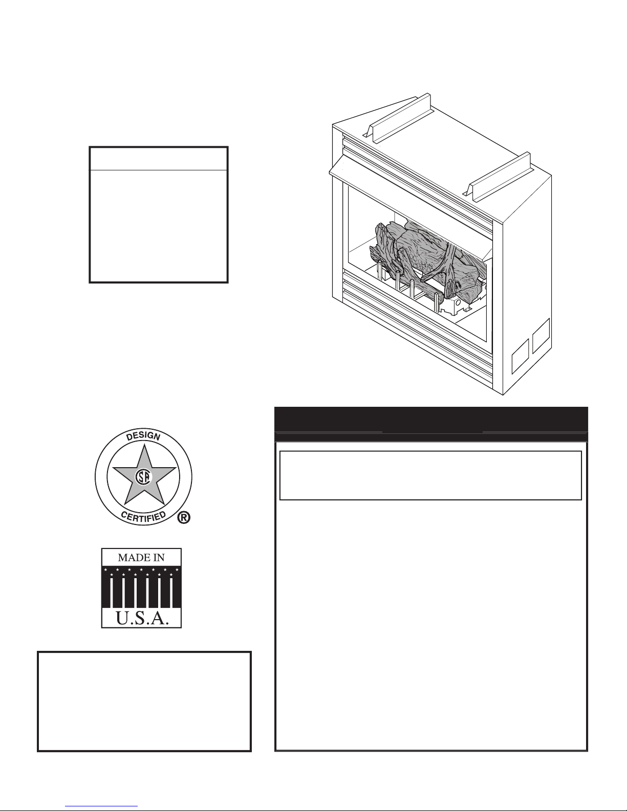
This is an unvented gas-fired
VENT-FREE FIREPLACE SYSTEMS
WARNINGS
– Do not store or use gasoline or other fl ammable
vapors and liquids in the vicinity of this or any
– WHAT TO DO IF YOU SMELL GAS
• Do not try to light any appliance.
• Do not touch any electrical switch; do not use
• Immediately call your gas supplier from a
• If you cannot reach your gas supplier, call the
– Installation and service must be performed by
WARNINGS
WARNINGS

................................
3
.....................................................
....................................................
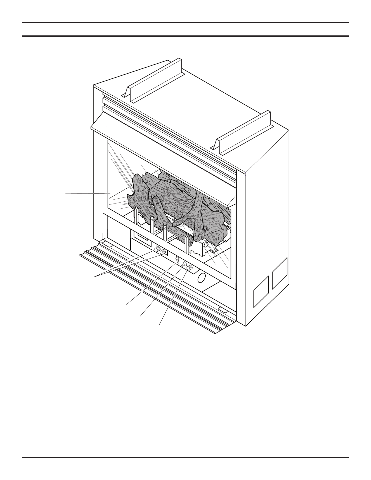
Pilot
.......................................................................
Thermal Generator
Firebox Dimensions
..............................................
Codes
..................................................................
Adequate Combustion and Ventilation Air
Removing Screen
Installing Canopy
................................................
Securing Heater to Floor or Hearth
.....................
Installing Radiant Face Plates
.................................................
...............................................
Hi/Lo Remote Control
.........................................
Milli-Volt Control
..................................................
..................................
.
Connecting Remote Receiver
Checking System Operation
.................................................
.................................
Manual Control Lighting Instructions
..................
Hi/Lo Control Lighting Instructions
......................
Milli-Volt Control Lighting Instructions
Match Lighting Instructions
...............
.................................
Heater
Cabinet
................................................................
....................................................
Warranty

resulting from improper installation or operation,
placement instructions for proper installation.
Candles, incense, oil lamps, etc. produce
provided. See page 10.
1. Due to high temperatures, the appliance should
be located out of traffi c and away from furniture
2. Children and adults should be alerted to the hazard
3. Young children should be carefully supervised when
4. Do not place clothing or other fl ammable material
5. Any safety screen or guard removed for servicing
6. Installation and repair should be done by a qualifi ed
7. To prevent malfunction and/or sooting, an unvented
1. Due to high temperatures, the appliance should
2. Children and adults should be alerted to the hazard
3. Young children should be carefully supervised when
4. Do not place clothing or other fl ammable material
5. Any safety screen or guard removed for servicing
6. Installation and repair should be done by a qualifi ed
7. To prevent malfunction and/or sooting, an unvented
Early signs of
WARNING

WITH OTHER GASES.
recommended.
The initial break-in operation should last two to three
kPa).
been under water.
room heater is installed.
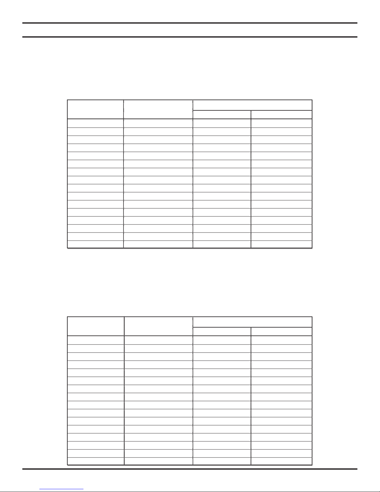
Pilot Regulator: 3.5" w.c. Pilot Regulator: 3.5" w.c.
Min. 5" w.c. Min. 5" w.c. Min. 6" w.c.
Min. 11" w.c. Min. 11" w.c. Min. 12" w.c.
Gas Rate
Gas Rate
Gas Rate
Gas Rate

- All gas to the gas logs is shut off at the valve.
- Valve position to light/maintain a standing pilot.
- Variable position corresponding to desired fl ame height.
Hi/Lo valve control has four (4) positions:
- Valve position to light/maintain a standing pilot.
- Valve position to turn ON.
- Variable position corresponding to desired fl ame height back to pilot.
Milli-Volt and T-Stat control has four (4) positions:
- All gas to the gas logs is shut off at the valve.
- Valve position to light/maintain a standing pilot.
- Valve position to turn ON/OFF log set with remote switch/thermostat.
- Variable position to control fl ame height (heat output). Both front and rear burners are in operation

• Unvented gas log grate/burner assembly
• Installation/operating instructions
• Ceramic fi ber logs
• Two (2) radiant face plates
• Plastic bag containing crushed volcanic rock
• Two (2) anchoring screws
• Canopy and fi ve (5) mounting screws
• Remote Control (Hi/Lo Model Only)
packaged with the log set.
• Hand held Remote with receiver
• Wall switch with 15' wire
• Wall thermostat with 15' wire
• Hand held Thermostat Remote with receiver
• Thermostat Sensor
WARNING
Do not attempt to install any part of the appliance unless you
WHAT YOU WILL NEED FOR INSTALLATION:
• External regulator (for propane/LPG and 1/2 lb. natural gas systems only)
• Piping which complies with local codes
• Pipe wrench or appropriate size crescent wrench set
• Pipe sealant approved for use with propane/LPG (Resistant to sulfur compounds)
• Sediment trap
• Manual shutoff valve
• Tee joint.
• Drill with 5/32 bit
• Phillips head screwdriver
1. Position fireplace in desired location. Refer to the
2. Install canopy and logs per instructions found in
3. Field wire main power supply to units with fan kit.
4. Install optional ON/OFF kit on units with milli-volt
5. Plumb gas line. Refer to the “Connecting the Gas”
6. Complete fi nish wall material and/or surround.
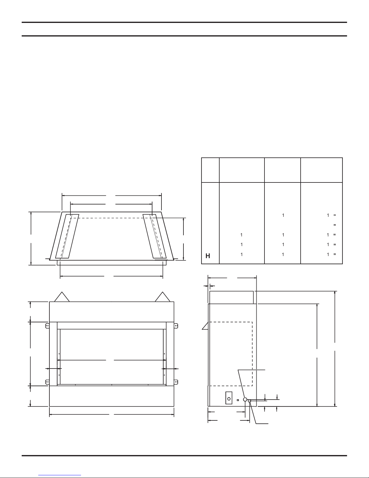
D
F
E
H
G
6 3/4"
6 3/4"
21"
2 1.2"
2 1/2"
5/8"
37 1/4"
33 3/4"
2 1/4"
1 1/4" Knockout
@ 2 1/4" HT
1 3/4"
7/8" Knockout @ 1 2/3" HT
13 5/8"
12 1/4"
C
B
A
DFS32A
DFS3224A DFS36 DFS42
37" 41" 47"
32" 36" 42"
16" 16" 16"
28
///
18
///////////
/

ADEQUATE COMBUSTION AND VENTILATION AIR
defi nes a confi ned space as a space whose volume is less than 50
per kw) of the aggregate input rating of all appliances installed in that
per kw) of the aggregate input rating of all appliances installed in that space. Rooms communicating directly
part of the unconfi ned space.
kg per pa/sec-m
b) weather striping has been added on openable windows and doors, and
WARNING
W
H
+ L
= 15
/
Ft., L
= 12 Ft., W = 12 Ft., H = 8 Ft.
/
+ 12) x (12) x (8)
+ 12) x (12) x (8)
/
x 1000
x 1000 = 52800 BTU/Hr
x 1000 = 29760 BTU/Hr
WARNING
WARNING
1. Remove the fi replace screen as described in the previous section.
2. Align the black canopy with the holes in the top frame assembly.
3. Install the three (3) screws (in ownerʼs manual packaging) which attach the canopy to the top frame assembly.
4. Tighten all screws. Make sure the canopy is level and secure. Install the fi replace screen.
WARNING
 Loading...