

Vermont Castings Defiant FlexBurn 1975 Installation And Operating Manual
Deant® FlexBurn® Non-Catalytic/Catalytic
Wood Burning Stove
Installation and Operating Manual
Model 1975
Report No. 227-S-40-2.
SAFETY NOTICE: IF THIS APPLIANCE IS
NOT PROPERLY INSTALLED, OPERATED
AND MAINTAINED, A HOUSE FIRE MAY
RESULT.
TO REDUCE THE RISK OF FIRE, FOLLOW
THE INSTALLATION INSTRUCTIONS. FAIL
URE TO FOLLOW INSTRUCTIONS MAY
RESULT IN PROPERTY DAMAGE, BODILY
INJURY OR EVEN DEATH. CONTACT LOCAL
BUILDING OFFICIALS ABOUT RESTRIC
TIONS AND INSTALLATION INSPECTION
REQUIREMENTS IN YOUR AREA.
The French language version of this manual is available online:www.vermontcastings.com
La version française de ce manuel est disponible en ligne : www.vermontcastings.com
-
-
DO NOT DISCARD THIS MANUAL. RETAIN FOR FUTURE USE.
For use in the
United States and Canada
30005220 0515 Rev. 25

Deant® FlexBurn® 1975 Non-Catalytic / Catalytic Wood Burning Stove
Welcome
Congratulations on your choice of a Vermont Castings Deant® stove. With this purchase you have made a commitment
to make the hearth a place of warmth, beauty and comfort in your home. At Vermont Castings Group, we share that
joy and appreciation for the hearth. We assure you that your cast-iron Vermont Castings stove has been made with the
utmost care and will provide you with many years of service.
As you become acquainted with your new stove, you will nd that its appearance is matched by its functionality, due to
cast iron’s unique ability to absorb and radiate heat.
Also, Vermont Castings Group products are among the cleanest-burning wood stoves and replaces available today. As
an owner of a Vermont Castings stove, you make a strong statement for pollution-free energy. However, clean burning
depends on both the manufacturer and the operator. Please read this manual carefully to understand how to properly
operate and maintain your stove.
At Vermont Castings Group, we are equally committed to your satisfaction as a customer. That is why we maintain
an exclusive network of the nest dealers in the industry. Our dealers are chosen for their expertise and dedication to
customer service. They are factory-trained and knowledgeable about every Vermont Castings Group product. Feel free
to contact your Authorized Vermont Castings Dealer anytime you have a particular question about your stove or its
performance.
®
This manual contains valuable instructions on the installation and operation of your Vermont Castings Deant
contains useful information on maintenance. Please read the manual thoroughly and keep it as a reference.
Sincerely,
Vermont Castings Group
. It also
This manual describes the installation, operation, and maintenance of the Vermont Castings Deant® Model 1975
Non-Catalytic / Catalytic wood burning heater. This heater meets the U.S. Environmental Protection Agency’s emission
limits for wood heaters sold on or after May 15, 2015. Under specic test conditions this heater has been shown to
deliver heat at rates ranging from 8,200 to 33,000 Btu/hr.
The Deant® Model #1975 has been tested and is listed by OMNI-Test Laboratories of Portland, Oregon. The test standards
are ANSI/UL-1482-2011 and ANSI/UL-737 for the United States, and ULC S627-00 for Canada. The Deant® is listed
for burning wood only. Do not burn other fuels. The Deant® is not approved for use in manufactured (mobile) homes.
We recommend that you hire a professional installer certied by the Wood Heat Education and Research Foundation
(WHERF) or the Wood Energy Technical Training (WETT) to install your stove, or to advise you on the installation should
you attempt to install it yourself.
Please read this entire manual before you install and use your new stove. Failure to follow instructions may result in
property damage, bodily injury, or even death.
Save These Instructions for Future Reference
2
30005220
Deant® FlexBurn® 1975 Non-Catalytic / Catalytic Wood Burning Stove
The Story of the Deant
No wood-burning appliance, save for Ben Franklin’s Pennsylvania Fireplace, has a stronger heritage than the Vermont
Castings Deant®. Named for a 19th-century steamship, the original Vermont Castings Deant® Wood Burning Stove
came to epitomize America’s resolve and independence during the Energy Crisis of the 1970s.
The year was 1975. With energy prices going through the roof, without an attractive or efcient wood stove to be found
anywhere, two entrepreneurs set out to create a stove that was both beautiful and highly functional. Finely crafted from
cast iron, the Deant® was the rst wood stove to combine an artistically designed exterior with a methodically engineered
interior, using new technologies for efcient combustion.
Americans purchased over a quarter-million Deant® stoves, as they rediscovered the common sense of heating with
wood, a home-grown fuel with none of the political and economic entanglements of foreign oil.
Thirteen years later, in 1988, Vermont Castings ‘retired’ the Deant®, replacing it with modern wood-burners such as the
Encore®. A decade later the Deant® was resurrected and updated with aesthetics and features that again led the industry.
In 2010, the third generation of the Deant® maintains the product’s rich tradition by introducing the most advanced
wood-burning stove on the market. The quality and classic look that consumers have come to expect from Vermont Castings is combined with the latest combustion technology, an innovative design that allows the stove to quickly be converted
to burn in either a catalytic or noncatalytic mode. In a sense, the Deant® Model 1975 has been 35 years in the making.
Due to its signicant role in American history, the original Deant® model is in the permanent collection of the Smithsonian
Institution in our nation’s capitol. Each new purchase of the Deant® continues that proud history.
®
Table of Contents
Specications .......................................................... 4
Installation ............................................................... 5
Clearance Charts................................................... 14
Assembly ............................................................... 18
Smoke Alarm/Safety Tips ...................................... 21
Operation ............................................................... 22
Draft Management ................................................. 29
Maintenance .......................................................... 31
The Catalytic Element ........................................... 34
Replacement Parts ................................................ 36
Warranty ................................................................ 39
Proposition 65 Warning: Fuels used in gas, woodburning or oil red appliances, and the products of combustion of such fuels, contain chemicals known to the State
of California to cause cancer, birth defects and other
reproductive harm.
California Health & Safety Code Sec. 25249.6
Installation Accessories
Warming Shelf
#0210 Classic Black
#0211 Biscuit
#0213 Ebony
#0218 Bordeaux
#0217 Brown Majolica
#0219 Twilight
#3265* Outside Air Kit
#3180 Outside Air Adapter
#1907 Firescreen
#1860 6" x 12" Oval Starter Pipe
FK26 Fan Kit
#3190 Connector Pipe Heat Shield
#0180 Rectangular Ceiling Kit
#0181 Round Ceiling Kit
A line of porcelain enamel stove pipe is available in
Biscuit, Bordeaux, Ebony, Brown Majolica colors.
*If you order #3265, you will also need #3180.
30005220
3
Deant® FlexBurn® 1975 Non-Catalytic / Catalytic Wood Burning Stove
DEFIANT
32³⁄₈"
(822 mm)
28⁷⁄₈"
(733 mm)
31¹⁄₂"
(800 mm)
5¹⁄₈"
(130 mm)
19"
(483 mm)
18"
(457 mm)
23³⁄₄"
(603 mm)
29⁷⁄₈"
(759 mm)
DEFIANT
23⁵⁄₈"
(600 mm)
19"
(483 mm)
26"
(660 mm)
C
L
28⁷⁄₈"
(733 mm)
Rear Venting
Specications
Deant
®
, Model 1975
EPA Emissions rating - Noncatalytic 2.3 g/hr*
Range of heat output - Noncatalytic 8,200 - 33,000
EPA Emissions rating - Catalytic 1.1 g/hr*
Efciency HHV - Noncatalytic/Catalytic 66/74**
Range of heat output Catalytic 10,000 to 30,300 BTU/hr.*
Peak heat output 75,000 BTU/hr.***
Area heated Up to 2,400 Square feet****
Fuel length 25"
Fuel capacity 70 pounds, hardwood
Loading Front and top
Chimney Connector:
for 8" ue collar 8" (203 mm) diameter
Chimney Flue Size:
with 8" Chimney Connector 8" (203 mm) minimum
with 6" Chimney Connector 6" (152 mm) minimum
Flue exit position Top or Rear
Primary Air
Manually Set, Thermostatically Maintained
Secondary Air Fixed, self-regulating
Ash handling system Removable ash pan
Glass panels High-temperature ceramic
Weight 518 lbs. (235 kg.)
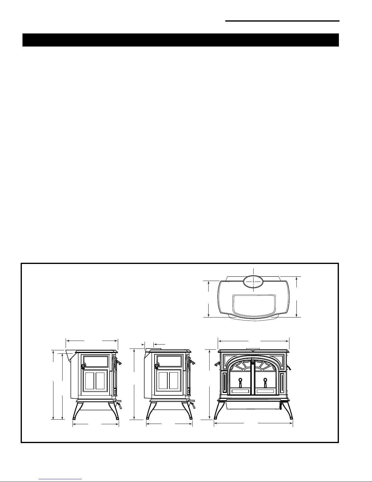
Width (leg to leg) 323⁄8" (822 mm)
Depth (leg to leg) 19" (483 mm)
Height to top of ue collar 297⁄8" (759 mm)
*Under specic conditions during EPA emissions testing.
**Efciency determined by CSA B415.10.
***This value can vary depending on how the stove is
operated, the type and moisture content of the fuel used,
as well as the design, construction and climatic location
of your home. Figures shown are based on maximum fuel
consumption rates obtained under laboratory conditions
and on average efciencies.
****These values are based on operation in building
code-conforming homes under typical winter climate conditions in New England. If your home is of nonstandard construction (e.g. unusually well insulated, not insulated, built
underground, etc.) or if you live in a more severe or more
temperate climate, these gures may not apply. Since so
many variables affect performance consult your Authorized
Dealer to determine realistic expectations for your home.
Drawing Not to Scale
Fig. 1 Deant® 1975 dimensions.
4
30005220

Deant® FlexBurn® 1975 Non-Catalytic / Catalytic Wood Burning Stove
30
25
20
15
0 2000 4000 6000 8000 10000 12000
Height
Altitude
Installation
SAFETY NOTICE: IF YOUR DEFIANT® IS NOT PROPERLY INSTALLED, A HOUSE FIRE MAY RESULT. TO
REDUCE THE RISK OF FIRE, FOLLOW THE INSTALLATION INSTRUCTIONS. CONTACT LOCAL BUILDING OR
FIRE OFFICIALS ABOUT RESTRICTIONS AND INSTALLATION INSPECTION REQUIREMENTS IN YOUR AREA.
Before you begin an installation, be sure that:
• Your stove and chimney connector will be far enough
from combustible material to meet all clearance requirements.
• The oor protector is large enough and is constructed
properly to meet all requirements.
• You have all necessary permits from local authorities.
Your local building ofcial is the nal authority for approving your installation as safe and determining that it meets
local and state codes.
The metal label permanently attached to the back of every
Vermont Castings’ stove indicates that the stove has been
tested to current UL and ULC standards, and gives the
name of the testing laboratory. Clearance and installation
information also is printed on the label. When the stove
is installed according to the information both on the label
and in this manual, local authorities usually will accept the
label as evidence that the installation meets codes and
can be approved.
However, codes vary in different areas. Before starting
the installation, review your plans with the local building
authority. Your local dealer can provide any additional
information needed.
For any unresolved installation issues, refer to the National
Fire Protection Association’s publication ANSI/NFPA 211
Standard for Chimneys, Fireplaces, Vents and Solid Fuel
Burning Appliances. For Canada, the equivalent publication is CSA CAN-B365 Installation Code for Solid Fuel
Burning Appliances and Equipment. These standards
are the basis for many national codes. They are nationally
recognized and are accepted by most local authorities.
Your local dealer or your local building ofcial may have a
copy of these regulations.
IMPORTANT: Failure to follow these installation instructions may result in a dangerous situation, including a
chimney or house re. Follow all instructions exactly,
and do not allow makeshift compromises to endanger
property and personal safety.
Outside Air
In some modern, super-insulated homes, there may be
inadequate air supply for combustion because of insuf-
cient air inltration into the building. Such air enters a
home through unsealed cracks and openings. Exhaust
fans in kitchens or bathrooms can compete with the stove
for available air and compound the problem.
When poor draft is caused by a low inltration rate, opening
a ground oor window on the windward side of the house
and near the stove will usually alleviate the problem.
A better solution is to install a permanent outside air supply
to the stove and/or room. In fact, bringing air for combustion
from outside the home directly to the air inlet of the stove
is required for new construction in some areas.
Pressure variations within the house do not affect a stove
equipped with an outside air supply, and improved stove
performance often results. An Outside Air Kit for the De-
®
is available from your local dealer.
ant
Chimney Height
Altitude affects chimney performance. When using an 8"
oval to 6" ue collar adapter on the Deant®, refer to Fig-
ure 1 for suggested chimney heights at various altitudes.
Chimney height should be measured from the ue collar
to the top of the chimney. The recommended minimum
chimney height is 16’ (5 m).
ST491
Fig. 2 Chimney height requirements with 6" chimney and/or
chimney connector.
30005220
5
Deant® FlexBurn® 1975 Non-Catalytic / Catalytic Wood Burning Stove
2' Min.
2' Min.
3'
Min.
0 To 10'
3'
Min.
0 To 10'
What Kind of Chimney to Use
You must connect the Deant® to a code-approved masonry
chimney with a ue liner, to a relined masonry chimney that
meets local codes, or to a prefabricated metal chimney that
complies with the requirements for Type HT chimneys in
the Standard for Chimneys, Factory-Built, Residential Type
and Building Heating Appliance, UL 103. Figure 3 illustrates
the two types. The chimney and chimney connector must
be in good condition and kept clean.
If you use an existing masonry chimney, it must be inspected to ensure it is in a safe condition before the stove
is installed. Your local professional chimney sweep, building
inspector, or re department ofcial will be able to inspect
the chimney or provide a referral to someone who can.
See “Chimney and Fireplace hazards”, in the appendix,
for particulars.
A prefabricated doublewall insulated chimney
Masonry Chimneys
An inspection of the chimney must conrm that it has a lining. Do not use an unlined chimney. The chimney should
have no cracks, loose mortar, other signs of deterioration,
and blockage. Repair any defects before the chimney is
used with your stove.
Unused openings in an existing masonry chimney must
be sealed with masonry to the thickness of the chimney
wall, and the chimney liner should be repaired. Openings
sealed with pie plates or wallpaper are a hazard and should
be sealed with mortar or refractory cement. In the event
of a chimney re, ames and smoke may be forced out of
these unused thimbles.
The chimney should be thoroughly cleaned before use.
A newly-built masonry chimney must conform to the standards of your local building code or, in the absence of a
local code, to a recognized national code. Masonry chimneys must be lined, either with code-approved masonry or
pre-cast refractory tiles, stainless steel pipe, or a code-approved, “poured-in-place” liner. The chimney’s clean-out
door must seal tightly. A loose or leaky clean-out door can
weaken chimney draft, causing performance problems.
Prefabricated Chimneys
A tile-lined
masonry
chimney
ST241
Fig. 3 Approved chimney types.
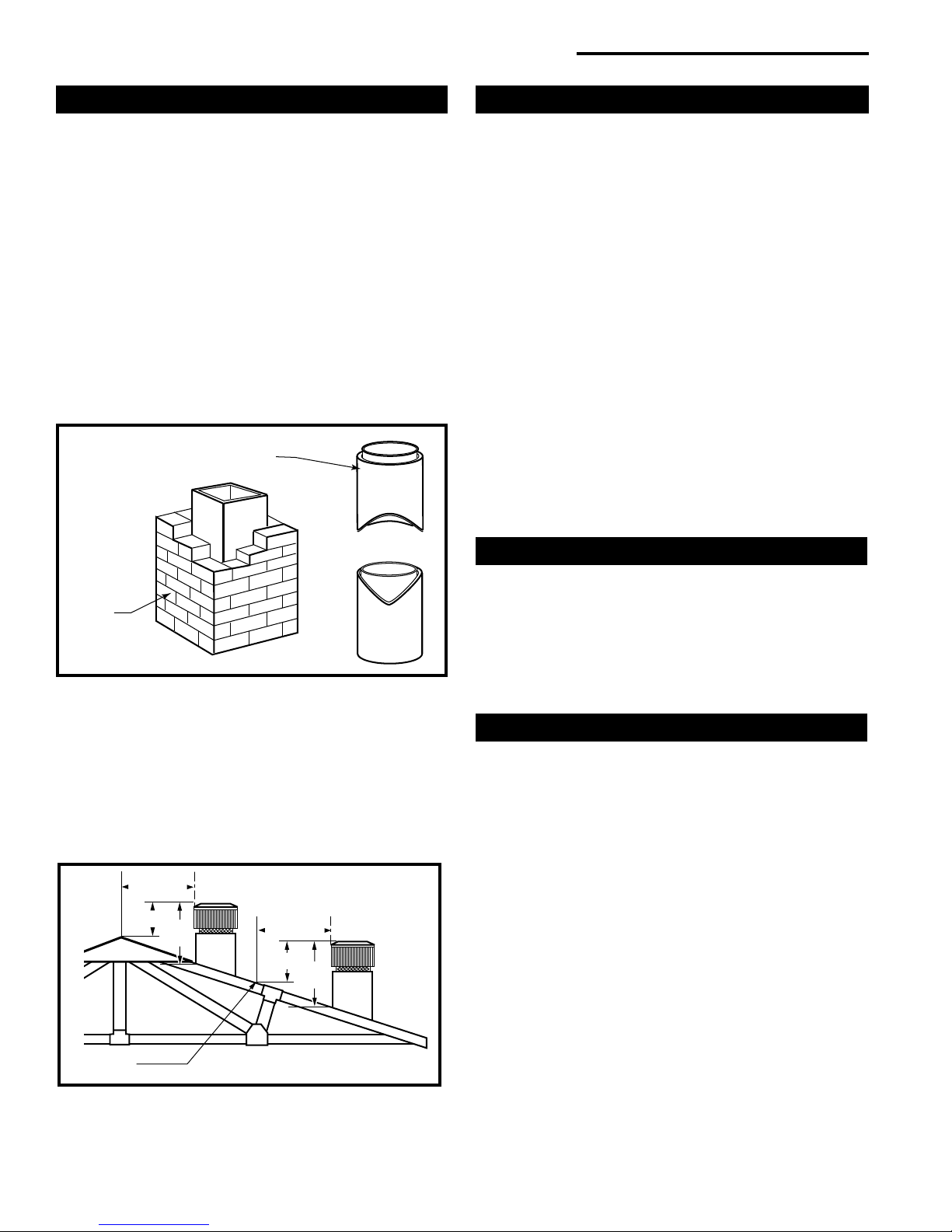
The chimney must extend at least 3’ (914 mm) above the
highest point where it passes through or near a roof, and at
least 2’ (610 mm) higher than any part of a building within
10’ (3 m) horizontally. (Fig. 4)
For proper draft and good performance, any chimney used
with a Deant® should extend at least 16’ (5 m) above the
ue collar of the stove.
Reference
Point
Fig. 4 The 2’-3’10’ Chimney Rule.
AC617
A prefabricated metal chimney must be one tested and
listed for use with solid-fuel burning appliances to the
High-Temperature (H.T.) Chimney Standard UL-103-1985
(2100°F) for the United States, and High Temperature
(650°C) Standard ULC S-629 for Canada.
DO NOT CONNECT THIS UNIT TO A CHIMNEY FLUE
SERVING ANOTHER APPLIANCE.
Chimney Size
A Deant® with an 8" (203 mm) ue collar is approved for
venting into a masonry chimney with a nominal ue size
of 8" x 8" (203 x 203 mm) or 8" x 12" (203 x 305 mm), and
into a round ue with nominal ue size of 8" (203 mm). A
Deant® with a 6" (152 mm) ue connector is approved for
venting into a masonry chimney with a nominal ue size of
8" x 8" (203 x 203 mm), and into a round ue with nominal
ue of 6" (152 mm).
NOTE: When installed with a 6" ue collar, the Deant®
may not be operated with the front doors open.
Whatever the ue collar size, a Deant® may be vented
into larger chimneys as well. However, chimneys with
liners larger than 8" x 12" (203 x 305 mm) may experience
rapid cooling of smoke and reduction in draft, especially if
the chimneys are located outside the home. These large
chimneys may need to be insulated or have their ues
relined for proper stove performance.
6
30005220
Deant® FlexBurn® 1975 Non-Catalytic / Catalytic Wood Burning Stove
Accessories to help make the connection between stain-
less steel chimney liners and your Deant® are available
through your local dealer.
Chimney Connector Guidelines
A chimney connector is the single-wall pipe that connects the stove to the chimney. The chimney itself is the
masonry or prefabricated structure that encloses the ue.
Chimney connectors are used only to connect the stove
to the chimney.
Single-wall connectors should be made of 24 gauge or
heavier steel. Do not use galvanized connector; it cannot
withstand the high temperatures that can be reached by
smoke and exhaust gases, and may release toxic fumes
under high heat. The connector may be 6" (152 mm) or 8
“ (203 mm) in diameter.
If possible, do not pass the chimney connector through
a combustible wall or ceiling. If passage through a combustible wall is unavoidable, refer to the section on Wall
Pass-Throughs. Do not pass the connector through an
attic, a closet or similar concealed space. The whole connector should be exposed and accessible for inspection
and cleaning.
In horizontal runs of un shielded chimney connector, maintain a distance of 30" (762 mm) from the ceiling. Keep it
as short and direct as possible, with no more than two 90°
turns. Slope horizontal runs of connector upward 1/4" per
foot (6mm per meter) going from the stove toward the chimney. The recommended maximum length of a horizontal
run is 3’ (1 m), and the total length should be no longer
than 8’ (2.4 m). In cathedral ceiling installations, extend the
prefabricated chimney downward to within 8’ (2.4 m) of the
stove. This will help maintain a good draft by keeping the
smoke warm, so that it rises readily.
Wear gloves and protective eyewear when drilling, cutting
or joining sections of chimney connector.
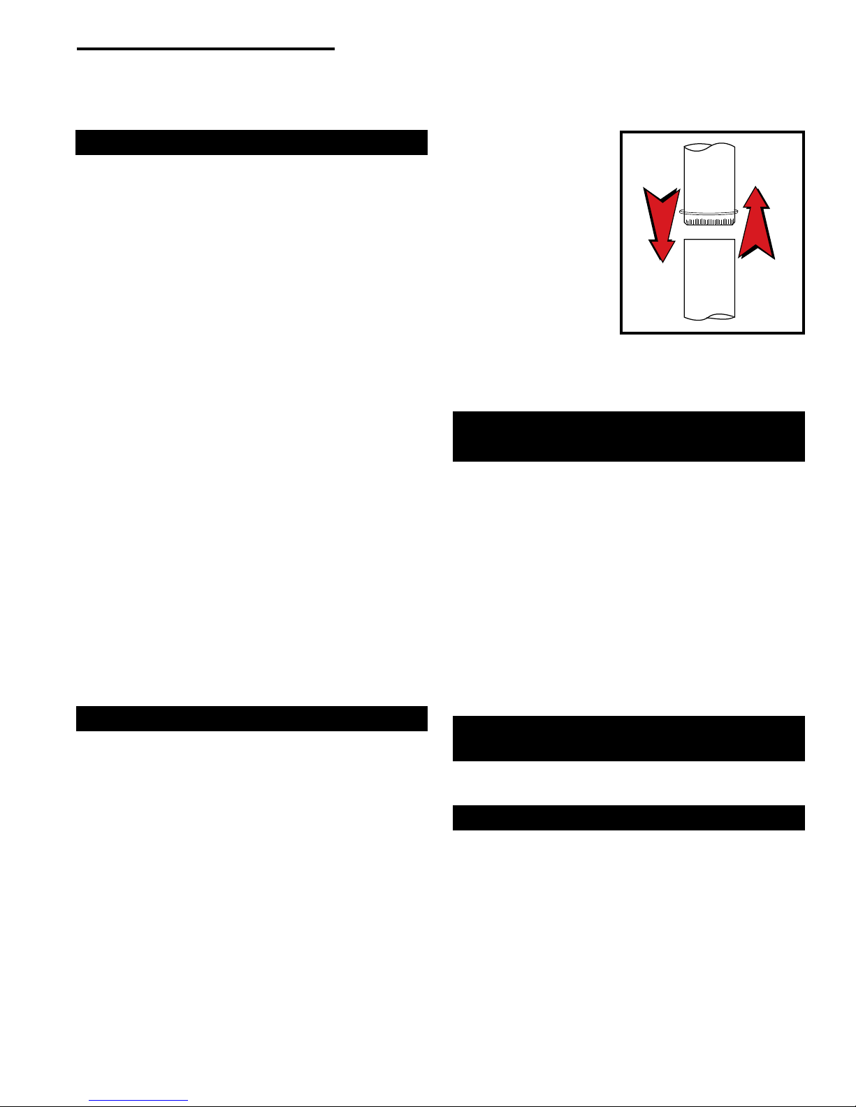
Single-wall Chimney Connectors
•
Begin assembly at the ue collar of the stove. Insert the
rst crimped end into the stove’s ue collar, and keep
each crimped end pointing toward the stove. (Fig. 5)
Using the holes in the ue collar as guides, drill 1/8" (3
mm) holes in the bottom of the rst section of chimney
connector and secure it to the ue collar with three #10
x 1/2" sheet metal screws. Lift off the griddle, and shield
the stove’s surface between the griddle opening and
the front of the ue collar to protect the nish when you
drill the front hole.
• Fasten each joint between sections of chimney con-
nector, including telescoping joints, with at least three
(3) sheet metal screws. The pre-drilled holes in the top
of each section of chimney connector serve as guides
when you drill 1/8" (3 mm) holes in the bottom of the
next section.
• Fasten the chimney connector to the chimney. Instruc-
tions for various installations follow. Figure 6 illustrates
the general layout of
chimney connector
parts.
• Be sure the installed
stove and chimney
connector are correct distances from
nearby combustible
materials.
NOTE: Special slip pipes
and thimble sleeves that
form telescoping joints
between sections of
chimney connector are
available to simplify installations. They often eliminate the
need to cut individual connector sections. Consult your
local dealer about these special pieces.
Toward
Stove
Flue Gas
Direction
ST242
Fig. 5 Chimney connector.
Securing the Single-wall Connector to a
Prefabricated Chimney
Follow the installation instructions of the chimney manufacturer exactly as you install the chimney. The manufacturer
of the chimney will supply the accessories to support the
chimney, either from the roof of the house, at the ceiling of
the room where the stove is installed, or from an exterior wall.
Special adapters are available from your local dealer to
make the connection between the prefabricated chimney
and the chimney connector. The top of such adapters
attaches directly to the chimney or to the chimney’s ceiling support package, while the bottom of the adapter is
screwed to the chimney connector.
These adapters are designed so the top end will t outside
the inner wall of the chimney, and the bottom end will t
inside the rst section of chimney connector.
Securing the Single-wall Connector to a
Masonry Chimney
Both freestanding masonry chimneys and replace masonry
chimneys may be used for your installation.
Freestanding Installations
If the chimney connector must pass through a combustible
wall to reach the chimney, follow the recommendations in
the Wall Pass-Through section that follows. The opening
through the chimney wall to the ue (the “breech”) must
be lined with either a ceramic or metal cylinder, called
the “thimble,” which is cemented securely in place. Most
chimney breeches incorporate thimbles, but the t must be
snug and the joint between the thimble and the chimney
wall must be cemented rmly.
30005220
7
Deant® FlexBurn® 1975 Non-Catalytic / Catalytic Wood Burning Stove
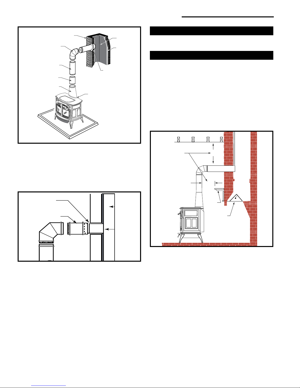
DEFIANT
*
*
Chimney
Elbow
Slip Pipe
Standard
Connector
Oval to
Round Adapter
Flue Collar
Fig. 6 An exploded view of the chimney connection in a freestanding masonry installation.
Flue
Flue Inner
Thimble
ST492
A special piece called the “thimble sleeve,” slightly smaller
in diameter than standard connectors and most thimbles,
will facilitate the removal of the chimney connector system
for inspection and cleaning. (Fig. 7) Thimble sleeves are
available from your local dealer.
Fireplace Installations
The chimney connector may be connected to the chimney
above the replace opening or through the replace.
Above the Fireplace
The Deant® may be connected to a chimney above a
replace opening. (Fig. 8) In such installations, the stove
is positioned on the hearth in front of the replace and the
chimney connector rises from the stove top and then angles
ninety degrees back into the chimney. The chimney liner
should extend to the point at which the chimney connector
enters the chimney.
If the chimney connector in your installation enters the
chimney above a replace, follow all the guidelines mentioned above for freestanding installations. In addition, give
special consideration to the following points:
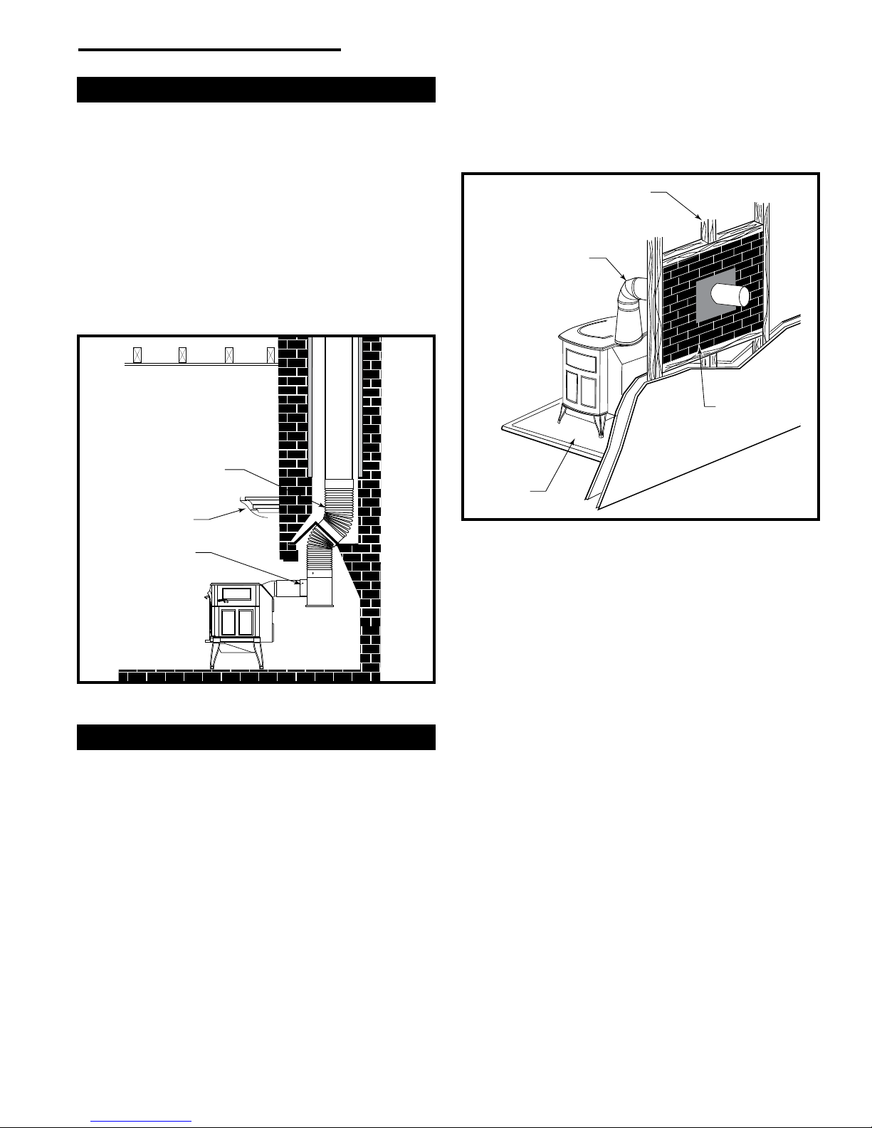
Check These
Clearances
Thimble Sleeve
Flue
Chimney Connector
Keep
sleeve
end ush
with ue
tile
ST243
Fig. 7 The thimble, made of either ceramic or metal, must be
cemented securely in place.
To install a thimble sleeve, slide it into the breech until it is
ush with the inner ue wall. Do not extend it into the actual
ue passage, as this could interfere with the draft.
The thimble sleeve should protrude 1-2" (25-50 mm) into
the room. Use furnace cement and thin gasketing to seal
the sleeve in place in the thimble. Secure the chimney
connector to the outer end of the sleeve with sheet metal
screws.
Without a thimble, a suitable length of chimney connector
can be extended through the breech to the inner face of
the ue liner, and cemented securely in place. Additional
pieces of connector are then attached with sheet metal
screws.
Mantel
Seal
This Off
ST244a
Fig. 8 In this installation, the chimney connector attaches to the
chimney above the replace opening.
• Check the clearance between the stove and the
chimney connector, and any combustible trim or the
mantel.
• Check the clearance between the chimney connector
and the ceiling. The clearance should be at least 30"
(762 mm) with unshielded connectors. Consult the
clearance charts for other installation options.
• The replace damper must be sealed to prevent room
air from escaping up the ue. However, it must be
possible to re-open the damper to inspect or clean the
chimney.
8
30005220
Deant® FlexBurn® 1975 Non-Catalytic / Catalytic Wood Burning Stove
D
E
F
I
A
N
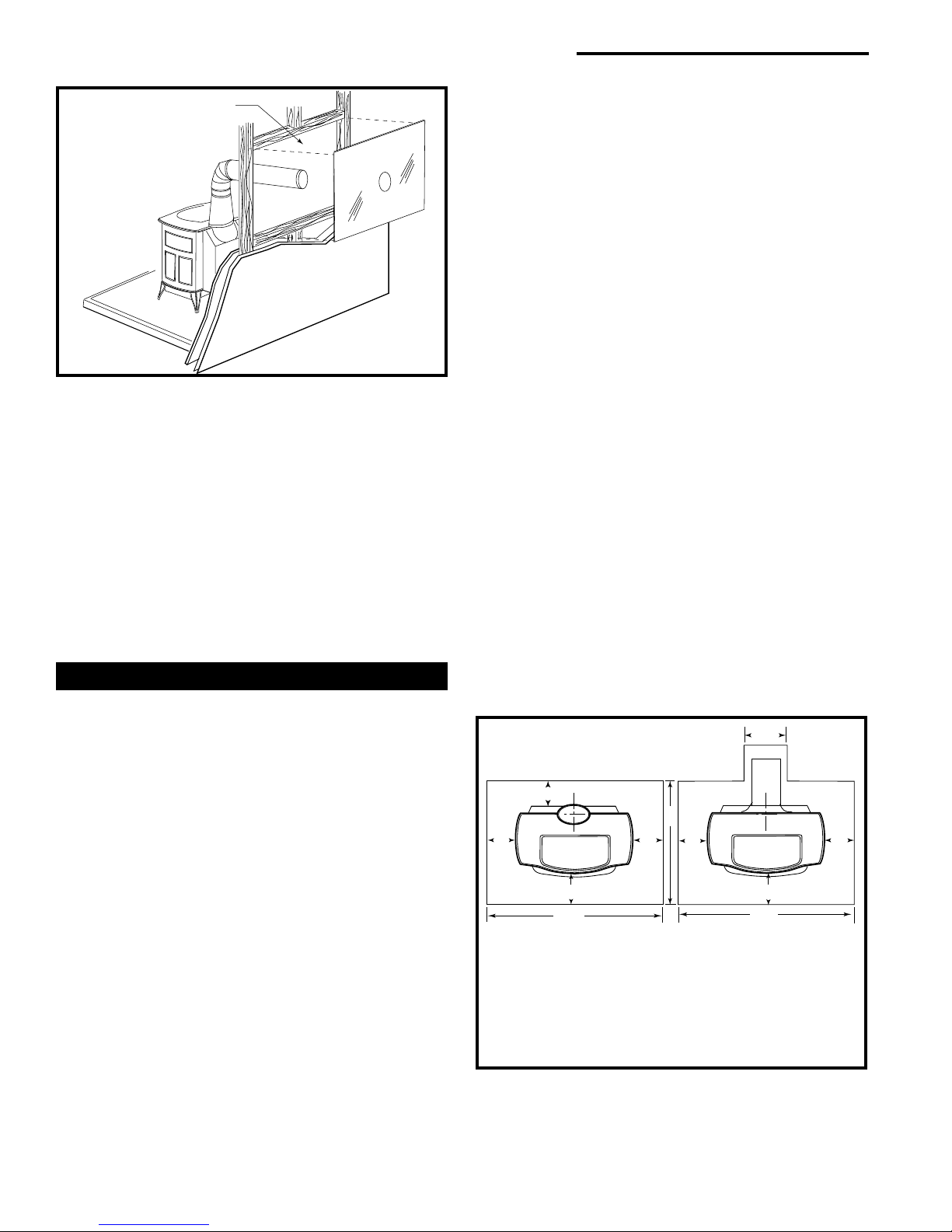
Through the Fireplace
If your replace opening height is at least 29" (737 mm),
you may install a Deant® through the opening using a
“positive connection” kit, available from your local dealer.
Positive connection kits ensure a tight t between the stove
ue collar and the chimney ue. (Fig. 9)
Fireplace installations, whether connected to the ue above
or through the replace opening, have special clearance
requirements to adjacent trim and the mantel. You’ll nd
the required safe clearances for Deant® replace instal-
lations on Page 13.
Floor protection requirements also apply to replace installations. This information is on Page 11.
Flexible
Connector
Mantel Shield
Fireplace Adapter Kit
“Positive Connection”
Figure 10 shows one NFPA-recommended method. All
combustible material in the wall is cut away from the single-wall connector to provide the required 12" (305 mm)
clearance. Any material used to close up the opening must
be noncombustible.
Wall Stud
Chimney
Connector
12" of
Noncombustible
Material
Floor Protection
Fig. 10 An approved wall pass-through for the United States.
Three other methods are also approved by the NFPA:
ST493
ST245
Fig. 9 Through the replace installation.
Wall Pass-Throughs
Whenever possible, design your installation so the connector does not pass through a combustible wall. If you are
considering a wall pass-through in your installation, check
with your building inspector before you begin. Also, check
with the chimney connector manufacturer for any specic
requirements.
Accessories are available for use as wall pass-throughs.
If using one of these, make sure it has been tested and
listed for use as a wall pass-through.
In the United States, the National Fire Protection Association (NFPA) has established guidelines for passing chimney
connectors through combustible walls. Many building
code inspectors follow these guidelines when approving
installations.
• Placing a section of chimney connector inside a venti-
lated thimble, which in turn is separated from combus-
tibles by 6" (152 mm) of berglass insulating material.
• Placing a section of chimney connector inside a section
of 9" (230 mm) diameter, solid-insulated, factory-built
chimney, with 2" (51 mm) of air space between the
chimney section and combustibles.
• Using a section of solid-insulated double-wall high
temperature chimney, with an inside diameter the same
as the chimney connector, at least one inch of solid
insulation, and a minimum of 9" (229 mm) air space
between the outer wall of the chimney section and
combustibles.
In Canada, The Canadian Standards Association has established different guidelines for wall pass-throughs. Figure
11 shows one method, in which all combustible material in
the wall is cut away to provide the required 18" (457 mm)
clearance for the connector. The resulting space must
remain empty. A ush-mounted sheet metal cover may
be used on one side only. If covers must be used on both
sides, each cover must be mounted on noncombustible
spacers at least 1" (25 mm) clear of the wall.
Your local dealer or your local building inspector can
30005220
9
Deant® FlexBurn® 1975 Non-Catalytic / Catalytic Wood Burning Stove
D
E
F
I
A
N
T
D
E
A
B
A
E
C
E
F
E
F
18" (460mm) clearance
between pipe and
sides/top/bottom of
opening
Fig. 11 An approved wall pass-through for Canada.
provide details for other approved methods of passing
a chimney connector through a combustible wall in your
area. In Canada, this type of installation must conform to
CAN/CSA-B365, Installation Code for Solid Fuel Burning
Appliances and Equipment.
NOTE: Do not vent your Deant® into a factory-built
(zero-clearance) replace. These appliances and their
chimneys are specically designed as a unit for use as
replaces. It may void the listing or be hazardous to adapt
them for any other use.
DO NOT CONNECT THE DEFIANT® TO ANY AIR DISTRIBUTION DUCT OR SYSTEM.
Floor Protection
A tremendous amount of heat radiates from the bottom
plate of your stove. The oor area directly under and
around the stove will require protection from radiant heat
as well as from stray sparks or embers that may escape
the rebox.
Heat protection is provided with the use of the Bottom Heat
Shield supplied with the stove.
Most installations will require the bottom heat shield to be
attached. Only when the stove is placed on a completely
noncombustible surface such as unpainted concrete over
earth may it be used without the heat shield.
With the bottom heat shield installed the Deant® 1975
was tested using a 1⁄2" (13mm) non-combustible hearth
material with a thermal conductivity, (k) = 0.47 BTU - in/
hr - ft2 -°F, resulting in the requirement of providing a total
thermal resistance (R) of 1.06. (Refer to “How to Determine
if Alternate Floor Protection Materials are Acceptable” sec-
tion.) The oor protector may be covered with a decorative
noncombustible material if desired. Do not obstruct the
space under the heater.
When using a re screen with doors open, UL737, Standard
for Fireplace Stoves, this unit was tested using a 1" (25mm)
ST494
non-combustible hearth pad with a thermal conductivity, (k)
= 0.47 BTU - in/hr - ft2 -°F, resulting in the requirement of
providing a total thermal resistance (R) of 2.12. (Refer to
“How to Determine if alternate Floor Protection Materials
are Acceptable” section.) The oor protector may be cov-
ered with a decorative noncombustible material if desired.
Do not obstruct the space under the heater. An 8" chimney
and chimney connector is required an the bypass damper
must be in the fully open position.
Important: All installations on a combustible oor require the use of the supplied bottom heat shield.
Protection requirements vary somewhat between the Untied States and Canada as follows:
In U. S. installations the oor protector is required under
the stove and must extend at least 16" (not including the
ash lip) from the front of the stove (“F”, Fig. 12), and at least
6" from the sides and rear. (“D” and “E”, Fig. 12)
In rear venting congurations, oor protection must also
extend under the chimney connector and 2" to either side.
(“C”, Fig. 12) For the 8" (203 mm) connector, the protector
must be a minimum of 12" (305 mm) wide. For the 6" (152
mm) connector, the protector must be 10" (254 mm) wide.
The protector must be centered under the connector.
To meet these requirements, a oor protector must be at
least 44" wide and 46" deep.
In Canada: A noncombustible oor protector is required
under the stove as well. The oor protector must extend
18" (457 mm) to the front (“F”, Fig. 12), and 8" (203 mm)
from the sides and rear. (“D” and “E”, Fig. 12)
To meet these requirements, a oor protector must be at
least 46" (1168 mm) wide and 50" (1270 mm) deep.
U.S. Canada
A. 44" 48" (1219 mm)
B. 46" 50" (1270 mm)
C. 12" 12" (305 mm) 8" Connector
10" 10" (250 mm) 6" Connector
D. 6" 8" (203 mm)
E. 6" 8" (203 mm)
F. 16" 18" (460 mm)
Fig. 12 Required oor protection dimensions.
ST500
10
30005220
Deant® FlexBurn® 1975 Non-Catalytic / Catalytic Wood Burning Stove
How to Determine if Alternate Floor
Protection Materials are Acceptable
All oor protection must be noncombustible (i.e. metals,
brick, stone, mineral ber boards, etc.). Any organic materi-
als (i.e. plastics, wood paper products, etc.) are combus-
tible and must not be used. The oor protection specied
includes some form of thermal designation such as R-value
(thermal resistance) or k-factor (thermal conductivity).
Procedure:
1. Convert specications to R-value:
i. R-value given - no conversion needed.
ii. k-factor is given with a required thickness (T) in
inches:
iii. K-factor is given with a required thickness (T) in
inches:
iv. r-factor is given with a required thickness (T) in
inches: R = r x T
2. Determine the R-value of the proposed alternate oor
protector:
i. Use the formula in Step 1 to convert values not ex-
pressed as R.
ii. For multiple layers, add R-values of each layer to
determine overall R-value.
3. If the overall R-value of the system is greater than the
R-value of the specied oor protector, the alternate is
acceptable.
EXAMPLE: The specied oor protector should be 1/2-inch
thick material with k-factor of 0.84. The proposed alternate
is 4" brick with an r-factor of 0.2 over 1/8" mineral board
with a k-factor of 0.29
Step a: Use formula above to convert specication to R-
value:
R = x T = x 0.5 = 0.59
Step b: Calculate R of proposed system.
4" brick of r = 0.2, therefore:
R
= 0.2 x 4 = 0.8
brick
1/8" mineral board of k = 0.29, therefore
R
mineralboard
R
total
= R
brick
Step c: Compare proposed system Rtotal of 1.231 to
specied R of 0.59. Since proposed system Rtotal is
greater than required, the system is acceptable.
Denitions
1
R = x T
k
1
k
1
0.29
1
K x 12
0.84
mineralboard
1
= 0.8 + 0.431 = 1.231
R = x T
= x 0.125 = 0.431
+ R
Floor Protection for Fireplace Installation
Do not assume that your replace hearth is completely
noncombustible. Many replace hearths do not satisfy the
“completely noncombustible” requirement because the brick
or concrete in front of the replace opening is supported by
heavy wood framing. Because heat passes readily through
brick or concrete, it can easily pass through to the wood.
As a result, such replace hearths can be a re hazard and
are considered a combustible oor.
For all replace installations, follow the oor protection
guidelines described above, including the need for a bottom
shield. Keep in mind that many raised hearths will extend
less than the required clearance from the front of the heat-
er. In such cases, sufcient oor protection as described
above must be added in front of the hearth to satisfy the
minimum oor protector requirement from the front of the
stove: 16" (410 mm) in the United States and 18" (460 mm)
in Canada. Hearth rugs do not satisfy the requirement for
oor protection as they are not re proof.
Fireplace installations also have special clearance require-
ments to the side walls, side decorative trim and replace
mantel. Refer to the information on replace and mantel
trim shields in this section.
Keep the Stove a Safe Distance
From Surrounding Materials
Both a stove and its chimney connector radiate heat in all
directions when operating, and nearby combustible materials can overheat dangerously if they are too close to the
heat source. A safe installation requires that adequate
clearance be maintained between the hot stove and its
connector and nearby combustibles.
Clearance is the distance between either your stove or
chimney connector, and nearby walls, oors, the ceiling,
and any other xed combustible surface. The Deant® has
specic clearance requirements that have been estab-
lished after careful research and testing. These clearance
requirements must be strictly observed.
In addition, keep furnishings and other combustible materials away from the stove. In general, a distance of 48"
(1219 mm) must be maintained between the stove and
moveable combustible items such as drying clothes, furni-
ture, newspapers, rewood, etc. Keeping those clearance
areas empty assures that nearby surfaces and objects will
not overheat.
Safe Ways to Reduce Clearances
R =
K =
(ft2)(hr)(°F)
Btu
(Btu)(ft)
(ft2)(hr)(°F)
k = = K x 12
r = =
30005220
(Btu)(in)
2
)(hr)(°F)
(ft
(ft2)(hr)(°F)
(Btu)(in)
Clearance requirements are established to meet every
installation possibility, and they involve the combination
of these variables:
1
k
• When the stove pipe has no listed heat shield mounted
on it.
• When the wall has no heat shield mounted on it.
11
Deant® FlexBurn® 1975 Non-Catalytic / Catalytic Wood Burning Stove
1" (25mm)
1/4" (6mm)
• When the wall has a heat shield mounted on it.
• When the wall and stove pipe have heat shields.
In general, the greatest clearance is required when you
place a stove and its connector near a wall with no heat
shield.
For example, when the Deant® is installed parallel to the
rear wall and no connector shield is used, it must be at
least 15" (381 mm) from the wall behind it and at least 21"
(533 mm) from walls on either side. These dimensions
are measured from the top edge of the stove to the combustible wall.
If the Deant® is installed in a corner and no shield is used,
the corners of the stove top must be at least 5" (127 mm)
from nearby walls.
Clearances may be reduced only by means approved by
the regulatory authority, and in accordance with the clearances listed in this manual. Refer to Page 14 for approved
clearance reduction specications.
NOTE: A minimum ceiling height of 8’ (2.4 m) is required
for all installations of the Deant®.
NOTE: Installation of the Deant® is not permitted in
alcoves.
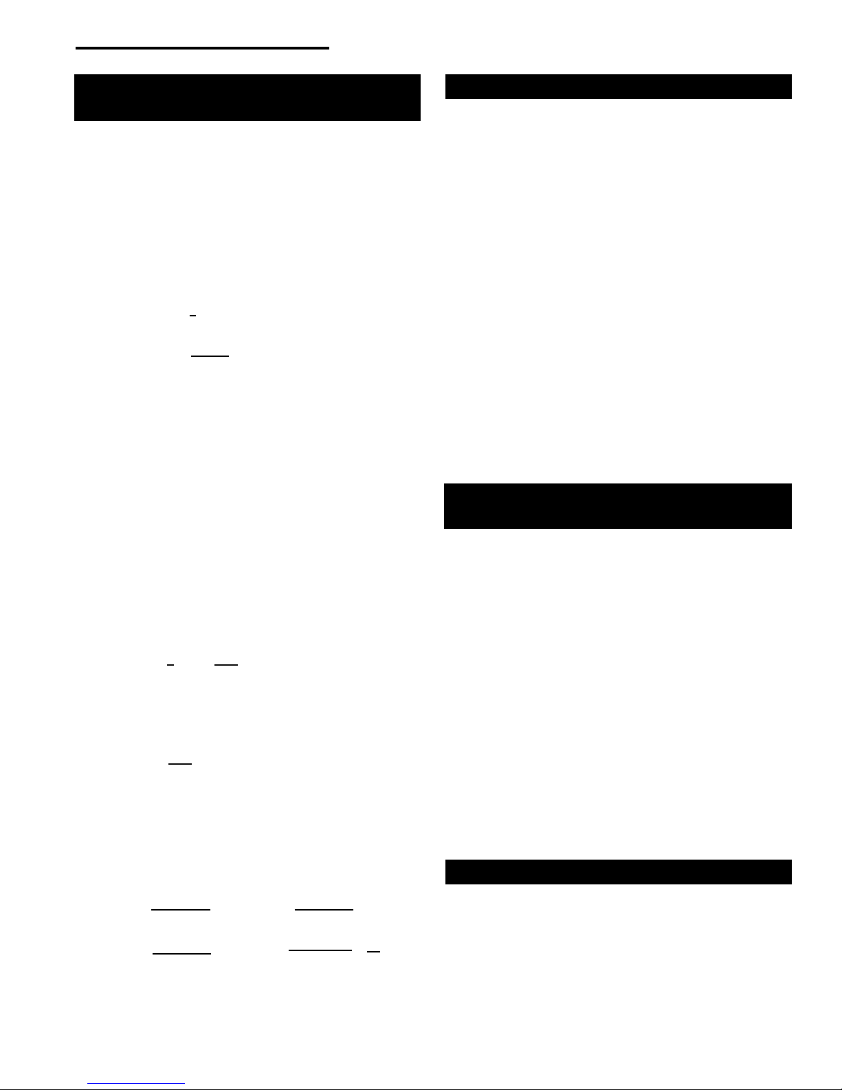
Wall Shields
One way to reduce clearances is with a wall shield constructed of 24 gauge or heavier sheet metal, or of another
noncombustible material such as 1/2" (13 mm) insulation
board such as Durock® or Wonderboard®, or common brick
“laid on at,” with the 31⁄2" (90 mm) side down.
Shields must be spaced out from the combustible surface
1" (25 mm) on noncombustible spacers, as in Figure 13.
The spacers should not be directly behind the stove or
chimney connector.
Air must be able to ow between the wall and the shield.
At least 50% of the bottom 1" (25 mm) of the shield must
be open, and the shield must be open at the top. Metal
screening across the top will keep small stray objects from
being trapped behind the shield. (Fig. 13)
The shield must be a minimum of 48" (1219 mm) tall, and
must extend at least 19" (483 mm) higher than the top
of the stove, whichever is higher. The shield behind the
chimney connector must be 30" (760 mm) wide, centered
behind the pipe; for installations that use an approved
prefabricated chimney to pass through the ceiling, the
shield behind the chimney connector must stop 1" (25 mm)
below the ceiling.
With 8" connections and chimneys, because of potentially
higher pipe temperatures, the shield must extend the full
height of the wall (up to 9’ (2.7 m)) and stop 1" (25 mm)
below the ceiling.
Air Flow
Screen
Wall Shield
Stud Wall
Framing
Noncombustible
Spacers and
Fasteners
Drywall
Air Flow
Fig. 13 Approved wall shield construction.
Shield
Metal Spacer
ST248
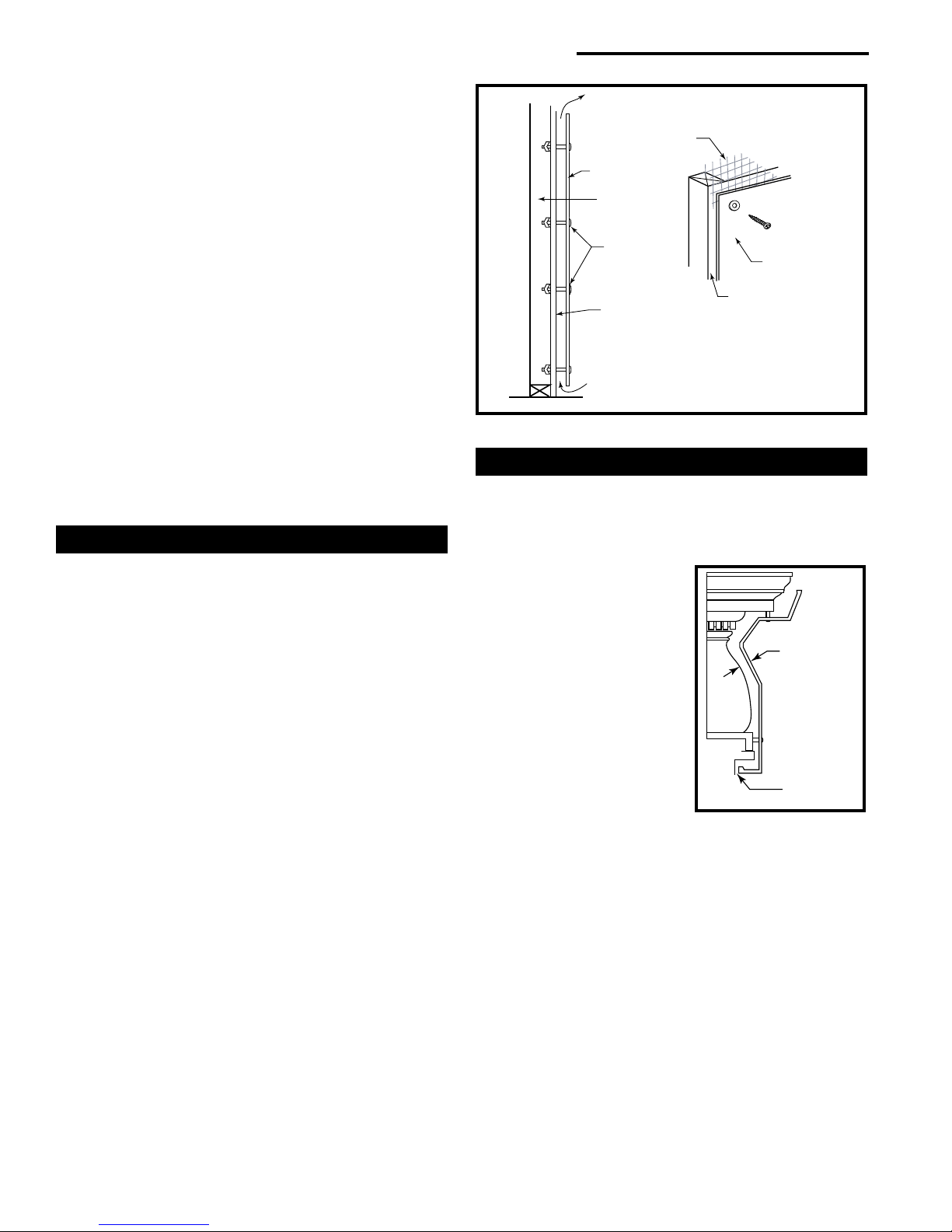
Fireplace and Mantel Trim Shields
A replace installation requires special clearance between
the side of the stove and the right and left walls, between
the side of the stove and the decorative side trim on the
replace face, and between the top of the stove and the
mantel.
Noncombustible shields
installed 1" (25 mm) away
from the combustible surface
on noncombustible spacers,
called ventilated shields, may
be used to reduce clearances.
To protect a mantel from the
heat of a stove in a replace
installation, use a custom-made
ventilated mantel shield that is
at least 48" (1220 mm) long,
centered over the stove. (Fig.
14) Ventilated shields for side
trim must extend the full length
of the trim.
An unprotected mantel (“A”, Fig. 15) cannot be more than
9" (230 mm) deep and must have a minimum clearance of
41" (1041 mm), measured from the stove’s top plate. With
a ventilated shield, this clearance may be reduced safely
to 29" (737 mm).
Unprotected top trim (B) protruding 3/4" (19 mm) or less
from the face of the replace must be a minimum of 28"
(711 mm) from the stove’s top surface. With a ventilated
trim shield, this clearance may be reduced safely to 21"
(533 mm).
Unprotected side trim (C) that protrudes 3/4" (19 mm) or
less from the face of a replace must have a minimum
clearance of 14" (356 mm), measured from the stove’s top
ST501
Fig. 14 A custom-formed
mantel shield.
12
30005220
 Loading...