

Vermont Castings CFX24NV, CFX32NV, CFX24PV, CFX32PV Installation And Operating Instructions Manual
CFX Series Vent Free Gas Fireplace
Installation and Operating Instructions
Models: CFX24, CFX32 Millivolt Control, Natural Gas
or Liquid Propane
WARNING: FIRE OR EXPLOSION HAZARD
If the information in this manual is not followed
exactly , a fi re or explosion may result causing
property damage, personal injury or loss of life.
– Do not store or use gasoline or other
fl ammable vapors and liquids in the vicinity
of this or any other appliance.
– WHAT TO DO IF YOU SMELL GAS
• Do not try to light any appliance.
• Do not touch any electrical switch; do not
use any phone in your building.
• Immediately call your gas supplier from
a neighbor's phone. Follow the gas
supplier's instructions.
• If you cannot reach your gas supplier, call
the fi re department.
– Installation and service must be performed
by a qualifi ed installer, service agency or
the gas supplier.
This is an unvented gas-fi red heater. It uses air
(oxygen) from the room in which it is installed.
Provisions for adequate combustion and
ventilation air must be provided. Refer to Page 7.
INSTALLER: Leave this manual with the appliance.
CONSUMER: Retain this manual for future reference.
20301726 9/14 Rev. 6

CFX VENT FREE FIREPLACE SYSTEM
Thank you for purchasing a Vermont Castings Group product. We are proud to manufacture all of
our gas and wood burning appliances in the USA. We hope that you enjoy your new fi replace and
have many happy memories around it for years to come.
CONTENTS
Important Safety Information .................................3–4
Product Features and Specifi cations ....................5–6
Operation ................................................................5
Gas Pressures ........................................................5
Gas Specifi cations ..................................................5
Ignition Controls ......................................................5
Pilot .........................................................................5
Thermal Generator ..................................................5
Fireplace & Mantel Dimensions .................................6
Getting Started .............................................................7
Unpacking ...............................................................7
Installation Information ............................................ 7
Fireplace Location and Clearances ...........................8
Determining Fireplace Location ..............................8
Clearances and Height Requirements ...................8
Fireplace Installation .............................................9–12
Fireplace Installation in Wall ...................................9
Mantel Installation .................................................10
Firebox to Mantel Installation ................................10
Removing Screen ................................................. 11
Optional Firebrick Panels ...................................... 12
Gas Connection .................................................. 13–15
Check Gas Type ...................................................13
Install Gas Pipe to Fireplace/Burner .....................13
Connect the Gas ...................................................14
Check Gas Pressure ............................................. 15
Electrical Connections ........................................16–17
Electrical Wiring ....................................................16
Connecting Optional Wall Switch or Thermostat ...16
Connecting Remote Receiver ...............................17
Check System Operation ......................................17
Final Steps ..........................................................18–20
Proper Installation Sequence (CFX24) .................18
Proper Installation Sequence (CFX32) .................18
Place Rock Wool ...................................................19
Check Pilot Flame ................................................ 19
Correct Log Flame Appearance ........................... 19
Optional Equipment .............................................. 20
Operating Instructions ....................................... 20–23
Operating Instructions ........................................... 20
For Your Safety Read Before Lighting ..................21
Millivolt Control Lighting Instructions ....................22
To Turn Off Gas to Heater .....................................22
Match Lighting Instructions ..................................23
Cleaning and Servicing .........................................23
Troubleshooting ..................................................24–25
Replacement Parts .............................................26–28
Warranty .................................................................... 29
2
20301726
IMPORTANT SAFETY INFORMATION
CFX VENT FREE FIREPLACE SYSTEM
IMPORTANT
Read these instructions carefully before installing or trying to operate this vent-free gas heater.
WARNING:
• Any change to this heater or its controls can be dangerous.
• Improper installation or use of the heater can cause serious injury or death from fi re, burns, explosion
or carbon monoxide poisoning.
• Do not allow fans to blow directly into the fi replace. Avoid any drafts that alter burner fl ame patterns.
• Do not use a blower insert, heat exchanger insert or other accessory, not approved for use with this
heater where applicable.
1. Due to high temperatures, the appliance be located
out of traffi c and away from furniture and draperies.
2. Children and adults should be alerted to the hazard
of high surface temperature and should stay away
to avoid burns or clothing ignition.
3. Y oung children should be carefully supervised when
they are in the same room with the appliance.
4. Do not place clothing or other fl ammable material on
or near the appliance.
5. Any safety screen or guard removed for servicing an
appliance, must be replaced prior to operating the
heater.
6. Installation and repair should be done by a qualifi ed
service person.
7. To prevent malfunction and/or sooting, an unvented
gas heater should be cleaned before use at least
annually by a professional service person. More
frequent cleaning may be required due to excessive
lint from carpeting, bedding material, etc. It is
imperative that control compartments, burners and
circulating air passageways be kept clean.
8. CARBON MONOXIDE POISONING: Early signs of
carbon monoxide poisoning are similar to the fl u with
headaches, dizziness and/or nausea. If you have these
signs, obtain fresh air immediately. Have the heater
serviced as it may not be operating properly.
9. This unit complies with ANSI Z21.11.2 unvented heaters standard, latest edition.
10. Do not install the CFX Model in a bathroom or bedroom.
11. Correct installation of the ceramic fi ber logs, proper
location of the heater, and annual cleaning are necessary to avoid potential problems with sooting. Sooting,
resulting from improper installation or operation, can
settle on surfaces outside the fi replace. See log place-
ment instructions for proper installation.
12. Avoid any drafts that alter burner fl ame patterns. Do not
allow fans to blow directly into fi replace. Do not place
a blower inside burn area of fi rebox. Ceiling fans may
create drafts that alter burner fl ame patterns. Sooting
and improper burning will occur.
13. CAUTION: Candles, incense, oil lamps, etc. produce
combustion by-products including soot. Vent-free
appliances will not fi lter or clean soot produced by
these types of products. In addition, the smoke and/
or aromatics (scents) may be re-burnt in the vent-free
appliance which can produce odors. It is recommended
to minimize the use of candles, incense, etc. while the
vent-free appliance is in operation.
14. An unvented gas-fi red heater uses air (oxygen) from
the room in which it is installed. Provisions for adequate
combustion and ventilation air must be provided. See
installation guidelines.
15. This heater shall not be installed in a room or space
unless the required volume of indoor combustion air is
provided by the method described in the National Fuel
Gas Code, ANSI Z223.1/NFPA 54, the International
Fuel Gas Code or applicable local codes.
16. Keep room area clear and free from combustible
materials, gasoline and other fl ammable vapors and
liquids.
17. Unvented gas heaters are a supplemental zone heater.
They are not intended to be a primary heating appliance.
18. Unvented gas heaters emit moisture into the living
area. In most homes of average construction, this
does not pose a problem. In houses of extremely
tight construction, additional mechanical ventilation is
recommended.
19. During manufacturing, fabricating and shipping, various
components of this appliance are treated with certain
oils, fi lms or bonding agents. These chemicals are not
harmful but may produce annoying smoke and smells
20301726
3

CFX VENT FREE FIREPLACE SYSTEM
IMPORTANT SAFETY INFORMATION
as they are burned off during the initial operation of the
appliance; possibly causing headaches, or eye or lung
irritation. This is a normal and temporary occurrence.
The initial break-in operation should last two to three
hours with the burner at the highest setting. Provide
maximum ventilation by opening windows or doors to
allow odors to dissipate. Any odors remaining after this
initial break-in period will be slight and will disappear
with continued use.
20. Input ratings are shown in BTU per hour and are for
elevations up to 2,000 feet. For elevations above 2,000
feet, input ratings should be reduced 4 percent for each
1,000 feet above sea level. Refer to the National Fuel
Gas Code.
21. The appliance and its appliance main gas valve must
be disconnected from the gas supply piping system
during any pressure testing of that system at test pressures in excess of 1/2 psig (3.5 kPa).
22. The appliance must be isolated from the gas supply
piping system by closing its equipment shutoff valve
during any pressure testing of the gas supply piping
system at test pressures equal to or less than 1/2 psig
(3.5 kPa).
23. Do not use this room heater if any part has been under
water. Immediately call a qualifi ed service technician
to inspect the room heater and to replace any part of
the control system and any gas control which has been
under water.
24. Never burn solid fuels in a fi replace where a unvented
room heater is installed.
25. Always have a fi replace screen in place when the
appliance is in operation, and unless other provisions
for combustion air are provided, the screen shall have
an opening(s) for induction of combustion air.
26. Do not fi ll spaces around the fi rebox with insulation or
other materials. These spaces must be maintained to
prevent the fi rebox from coming in contact with com-
bustible materials.
This appliance may be installed in an aftermarket,
permanently located, manufactured (mobile)
home, where not prohibited by local codes.
This appliance is only for use with the type of
gas indicated on the rating plate. This appliance
is not convertible for use with other gases.
CODES
Adhere to all local codes or, in their absence, the latest
edition of THE NA TIONAL FUEL GAS CODE ANSI Z223.1
or NFPA54 which can be obtained from…
American National Standards Institute, Inc.
1430 Broadway
New York, NY 10018
or
National Fire Protection Association, Inc.
Batterymarch Park
Quincy, MA 02269
4
20301726
PRODUCT FEATURES & SPECIFICATIONS
OPERATION
This unvented gas heater requires no outside venting and
burns cleanly with high heating effi ciency.
This zero-clearance unvented gas heater can be installed
against any wall that is accessible to a gas line.
CFX VENT FREE FIREPLACE SYSTEM
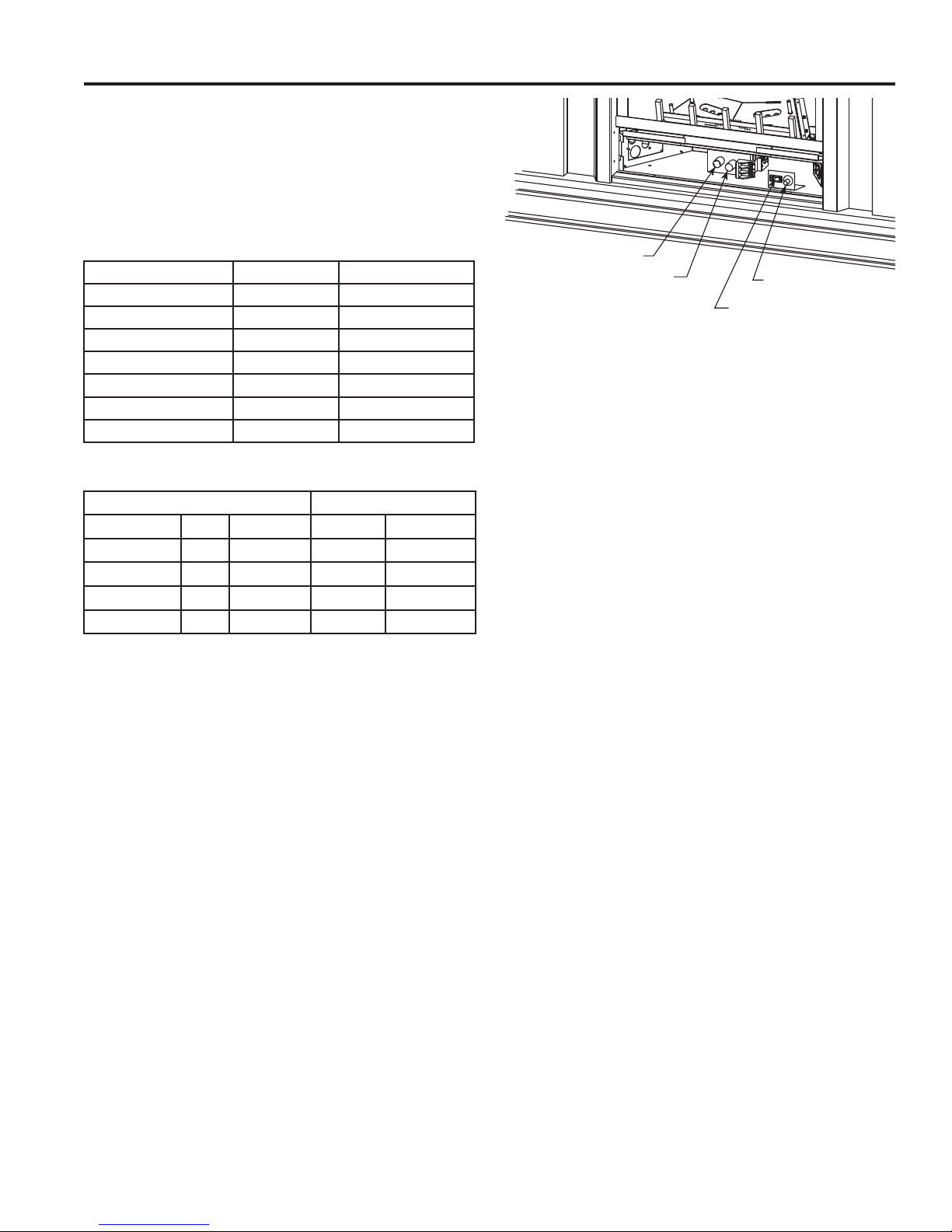
GAS PRESSURES
Control Fuel Millivolt
Regulator Pressure Natural Gas 3.5" w.c.
Pilot Regulator Natural Gas 3.5" w.c.
Max. Inlet Pressure Natural Gas 10.5" w.c.
Min. Inlet Pressure Natural Gas 5.0" w.c.
Regulator Pressure LP 10.0" w.c.
Max. Inlet Pressure LP 13.0" w.c.
Min. Inlet Pressure LP 11.0" w.c.
GAS SPECIFICATIONS
Input BTU/hr.
Model Fuel Control Max. Min.
CFX24NV Nat. Millivolt 22,000 17,000
CFX24PV LP Millivolt 22,000 17,000
CFX32NV Nat. Millivolt 26,000 20,000
CFX32PV LP Millivolt 26,000 20,000
NOTE: For LP models an external regulator is required
to reduce supply pressure to a maximum of 13" w.c.
HI/LO Control Knob
Control Knob
Figure 1 Control Access Door Shown Open
On/Off Switch
Piezo Igniter
PILOT
The gas log heater is fi tted with a specially designed safety
pilot light which senses the amount of oxygen available in
the room and shuts the gas log heater off if the oxygen level
begins to drop below a satisfactory level. The pilot can only
be re-lit when adequate fresh air is available.
THERMAL GENERATOR
The millivolt gas log pilot is fi tted with a millivolt generator
to provide power for remote activation.
IGNITION CONTROLS
The Piezo igniter allows ignition of the pilot without the use
of matches or batteries.
The millivolt control has four (4) positions:
OFF - All gas to the gas logs is shut off at the
valve.
IGN - Valve position to light/maintain a stand-
ing pilot.
ON - V alve position to turn ON/OFF log set
with remote switch/thermostat.
LOW/HI - Variable position to control fl ame height
(heat output). Both front and rear burners are in operation to provide realistic
glow and yellow fl ame.
20301726
5
CFX VENT FREE FIREPLACE SYSTEM
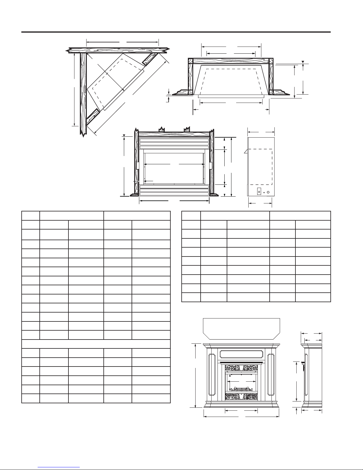
FIREPLACE & MANTEL DIMENSIONS
S
R
S
Q
Min. Rough
Opening
Height
N
1/2”
or 5/8”
I
O - Min. Rough Opening Width
B
A
D
L
M
J
G
C
E
F
K
Min. Rough
Opening
Depth
P
H
Ref. CFX24(N/P)VWM CFX32(N/P)VWM
A24
B22
C26
1
⁄2" (622 mm) 32" (813 mm)
1
⁄2" (572 mm) 283⁄4" (730 mm)
1
⁄2" (673 mm) 30" (762 mm)
D 14" (356 mm) 213⁄4" (553 mm)
E 17" (432 mm) 201⁄4" (514 mm)
F4
G4
H11
5
⁄8" (118 mm) 43⁄4" (121 mm)
7
⁄8" (124 mm) 5" (127 mm)
7
⁄8" (302 mm) 133⁄8" (340 mm)
I 1" (25 mm) 15⁄8" (41 mm)
J10
1
⁄2" (267 mm) 12" (305 mm)
K 9" (229 mm) 105⁄8" (270 mm)
L13
1
⁄8" (333 mm) 171⁄2" (445 mm)
M 21" (533 mm) 27" (686 mm)
Framing Dimensions
N26
O24
P10
Q42
R 21" (533 mm) 26
3
⁄4" (680 mm) 301⁄4" (768 mm)
3
⁄4" (629 mm) 321⁄2" (826 mm)
1
⁄2" (267 mm) 121⁄4" (311 mm)
1
⁄2" (1080 mm) 533⁄4" (1326 mm)
3
⁄4" (680 mm)
S 30" (762 mm) 38" (965 mm)
Figure 2 Fireplace and Framing Dimensions for CFXWM models
Ref. CFX24(N/P)(U/DW) CFX32(N/P)(U/DW)
T11
U19
V26
3
⁄4" (299 mm) 151⁄4" (387 mm)
3
⁄4" (502 mm) 26" (660 mm)
7
⁄8" (683 mm) 33" (838 mm)
W* 521⁄2" (1334 mm) 619⁄16" (1564 mm)
X* 44' (1118 mm) 503⁄4" (1289 mm)
Y26
5
⁄8" (676 mm) 305⁄8" (778 mm)
Z* 41⁄2" (114 mm) 4" (102 mm)
AA* 15" (381 mm) 181⁄4" (464 mm)
BB* 111⁄2" (292 mm) 147⁄8" (378 mm)
*Not applicable to CFXWM models.
AA
BB
X
T
U
V
W
Figure 3 Firebox Dimensions for CFXU and CFXDW models
Y
Z
AA
6
20301726
GETTING STARTED
CFX VENT FREE FIREPLACE SYSTEM
UNPACKING
Make sure you have received all parts:
Check your packing list to verify that all listed parts have
been received. You should have the following:
• Unvented gas heater
• Two (2) 90° angle brackets*
• Facing
• Installation/operating instructions
• Two (2) anchoring screws
• Cabinet*
• Ceramic fi ber logs
• Four (4) black screws *
*Not included with CFXWM models
Millivolt controlled heater designed to be operated with
optional devices for ON/OFF functions.
• Hand held Remote with receiver
• Wall T-stat with 20' wire
• Wall switch with 20' wire
• Hand held Thermostat Remote
Gloves are recommended when handling
ceramic fi ber logs to prevent skin irritation
from loose fi bers. Logs are fragile — handle
with care.
CAUTION
Carefully inspect the contents for shipping damage. If any
parts are missing or damaged, immediately inform the
dealer from whom you purchased the appliance. Do not
attempt to install any part of the appliance unless you
have all parts in good condition.
What you will need for installation:
You must have the following items available before pro-
ceeding with installation:
• External regulator (for propane/LPG only)
• Piping which complies with local codes
• Phillips head screwdriver
• Pipe sealant approved for use with propane/LPG
(Resistant to sulfur compounds)
• Pipe wrench
WARNING
Do not install the heater:
• Where curtains, furniture, clothing,
or other fl ammable objects are less
than 42" from the front of the heater.
• In high traffi c areas.
• In windy or drafty areas.
INSTALLATION INFORMATION
In planning the installation for the fi replace it is neces-
sary to determine where the unit is to be installed and
whether optional accessories are desired. Gas supply
piping should also be planned. The following steps represent the normal sequence of installation. Each installation is unique, however, and might require a different
sequence.
1. Determine desired location for fi replace. Refer to the
Location of Fireplace and Clearances and Height
Requirements sections in this manual.
NOTE: Be sure all packing material has been removed
from underside the unit.
2. Assemble mantel (if applicable) and install fi replace
according to the instructions in this manual.
2. Install logs per instructions found in this manual.
3. Field wire main power supply to units with fan kit. Refer
to the Electrical Section found in this manual. (Electrical
connections should only be performed by an experienced, licensed certifi ed tradesman).
4. Install optional ON/OFF kit on units with millivolt control.
Refer to the installation instructions included with the
kit and also refer to the Electrical Wiring section found
in this manual.
5. Plumb gas line according to the Connecting the
Gas section found in this manual. (Gas connections
should only be performed by an experienced,
licensed/certifi ed tradesman).
WARNING: If the area in which the heater
may be operated does not meet the
required volume for indoor combustion
air, combustion and ventilation air shall be
provided by one of the methods described in the
National Fuel Gas Code, ANSI Z223.1/NFPA 54,
the International Fuel Gas Code or applicable
local codes.
20301726
7
CFX VENT FREE FIREPLACE SYSTEM
FIREPLACE LOCATION & CLEARANCES
DETERMINING FIREPLACE LOCATION
Carefully select the best location for installation of your
unvented fi replace. The following factors should be taken
into consideration.
• Clearance to side wall, ceiling, woodwork and window
or other combustibles. Refer to Clearances and Height
Requirements section. Minimum clearances to combustibles must be maintained.
• Location must not be affected by drafts caused by
kitchen exhaust fans, ceiling fans, return air registers
for forced air furnaces/air conditioners, windows or
doors.
• Installation must provide adequate ventilation and com-
bustion air.
• DO NOT INSTALL THE CFX MODEL IN A BED-
ROOM OR BATHROOM.
• Location should be out of high traffi c areas and away
from furniture and draperies due to heat from fi rebox.
• Never obstruct the front opening of the unvented fi re-
place or restrict the fl ow of combustion and ventilation
air.
• Do not install in the vicinity where gasoline or other fl am-
mable liquids may be stored. The unvented fi rebox must
be kept clear and free from the combustible materials.
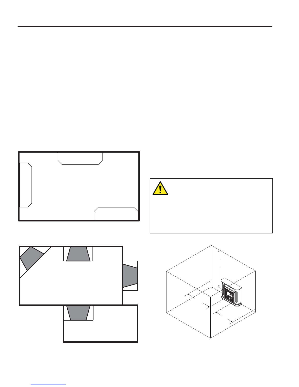
CLEARANCES AND HEIGHT REQUIREMENTS
Ensure that minimum clearances shown in Figure 5 are
maintained. Left and right clearances are determined when
facing the front of the fi rebox.
Follow these instructions carefully to ensure safe installation. Failure to follow these requirements may create a
fi re hazard.
1. Sidewall Clearances — The clearance from the inside
of the appliance to any combustible adjacent wall should
not be less than 9". Figure 5
2. Ceiling Clearance — The ceiling must be at least 42"
from the top of the fi rebox opening. Figure 5
3. Back W all Clearance — The appliance may be placed
against a combustible back wall.
Figure 4a Suggested Locations for CFXU or CFXDW models
WARNING: The dimensions shown in
Figure 4 are minimum clearances to
maintain in installing this heater. Left
and right clearances are determined when
facing the front of the heater.
Follow these instructions carefully to ensure
safe installation. Failure to follow instructions
exactly can create a fi re hazard.
42”
Min.
9”
Min.
9”
Min.
Figure 4bSuggested Locations for CFXWM models
8
Figure 5 Clearances and Height Requirements
20301726
FIREPLACE INSTALLATION
CFX VENT FREE FIREPLACE SYSTEM
Floor Clearance — The fi replace may be installed directly
on a combustible fl oor or a raised platform of an appropriate
height. Do not place fi replace on carpeting, vinyl, tile or
other soft fl oor coverings. It may, however , be placed on fl at
wood, plywood, particle board or other hard surfaces. Be
sure fi replace rests on a solid continuous fl oor or platform
with appropriate framing for support and so that no cold
air can enter from under the fi rebox.
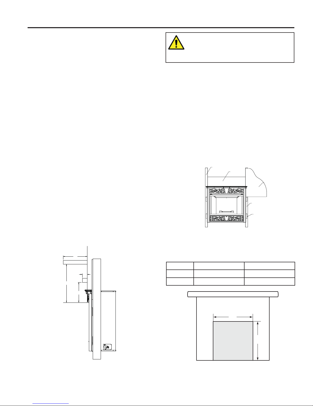
Mantel clearances — The CFX face must be installed. If a
combustible mantel is installed. It must meet the clearance
requirements detailed in Figure 6.
NOTE: The Vermont Castings Group Barrington Mantel
model series is specifi cally designed to comply with all
mantel temperature requirements. (The CFX32NVDW
uses the BWC400-DW. The CFX24NVDW uses the
BWC300-DW.) Any custom-built mantel must comply with
all clearance requirements shown in this instruction manual.
If unit is to be built in, the fi replace framing can be built
before or after the appliance is set in place. BE SURE THA T
ALL P ACKING MA TERIAL HAS BEEN REMOVED FROM
THE UNDERSIDE OF THE UNIT PRIOR TO SETTING
THE FIREBOX IN PLACE. Construct fi replace framing
following Figure 2 on Page 6 for fi replace dimensions. The
framing headers may rest directly on top of the fi rebox.
The fi replace may be installed directly on a combustible
fl oor or a raised platform of an appropriate height. Do
not place fi replace on carpeting, vinyl, tile or other soft
fl oor coverings. It may, however, be placed on fl at wood,
plywood, particle board or other hard surfaces. Be sure
fi replace rests on a solid continuous fl oor or platform with
appropriate framing for support and so that no cold air can
enter from under the fi rebox.
Anchor fi replace to the side framing members using nailing
fl anges.
12"
21⁄2"
19"
10"
WARNING: The fi replace must be installed
in accordance with the clearance and
height requirements identifi ed in this
manual.
FIREPLACE INSTALLATION IN WALL
Note: The information below applies only to the CFXWM
models.
1. Remove 5 total screws (3 top, 2 bottom) to remove front
face.
2. Select proper nailing fl anges located on each side of
the fi rebox and bend them out.
3. Slide the fi rebox into prepared framing or position fi rebox
in its fi nal position and frame later.
4. Level the fi rebox by checking the top edge of the fi rebox.
Shim if necessary.
5. Anchor fi rebox to the side framing members using 8d
nails or other suitable fasteners. Figure 7
6. Re-install CFX face.
Stud
Figure 7Nailing Flanges
When finishing a custom cabinet, mantel or other built-in
enclosure, the opening size to accommodate the fi replace with
trim installed is as follows:
Ref. CFX24 CFX32
J26
3
⁄4" (680mm) 311⁄4" (800mm)
K 25" (635mm) 3213⁄16" (833mm)
Header
Wall Board
Stud
Nailing flange
Figure 6 Mantel Clearances
20301726
K
J
Figure 8 Custom Cabinet
9
 Loading...