

Vermont Castings BC36MH, BC42MH Installation & Operating Manual
Manufactured Housing
Woodburning Fireplace
Homeowner’s Installation &
Operating Manual
For Models:
BC36MH, BC42MH
DO NOT DISCARD THIS MANUAL: Retain for future use.
7412972 1/13 Rev. 17
BC36MH, BC42MH Woodburning Fireplace
Safety Information
Please Read This Manual Before Installing And Using Fireplace
IMPORTANT: Read all instructions and warnings carefully before starting installation. Failure to follow these instructions
may result in a possible re hazard and will void the warranty.
Description
The BCMH replace is a solid fuel, heat circulating woodburning replace engineered for use in manufactured
housing.
Precautions
Vermont Castings Group replaces and component parts
have been highly tested and will operate safely when
installed in accordance with instructions provided in this
manual. Carefully read and understand all instructions
before beginning installation.
If you notice any damage to replace or component parts,
immediately report damage to your Vermont Castings
Group dealer.
Only use Vermont Castings Group components or the warranty will be voided and a re hazard may be created.
Vermont Castings Group warranty will be voided by and
Vermont Castings Group disclaims any responsibility for
the following actions:
• Installation of any damaged replace or chimney
component;
• Modication of replace, chimney assembly or
any component parts thereof; (except for chase
ashings as detailed in the Chimney Top installation
instructions).
• Installation other than as instructed by Vermont
Castings Group; or
• Installation and/or use of any component part not
manufactured or approved by Vermont Castings
Group in combination or assembly with a Vermont
Castings Group replace system, notwithstanding any independent testing laboratory or other
third party approval of such component parts or
accessory.
Any such action may possibly cause a re hazard.
Consult local building codes to ensure that you are in
compliance before installing the replace.
Fireplaces must be vented to the out-of-doors.
Do not obstruct or modify air inlets/outlets in any
manner.
Do not install combustible materials on any of the black
replace surround.
Burn only solid wood fuel or gas logs.
Do not install a solid fuel burning insert or other
products not specied for use with this replace.
Drafts
A guide for home designers and installers:
To help prevent performance problems of this replace,
such as spillage of combustion products into the living
space, conditions should be avoided that cause negative
pressure in the surrounding area. The replace should not
be located in areas that can have negative drafts. These
can include small rooms with frequently swinging doors,
or the presence of large furnace intake return air registers
located close to the replace.
Gas Logs
If you plan to install a gas log, the gas line should be
installed before framing the replace. The gas line must
be installed by a certied gas line installer.
Proposition 65 Warning: Fuels used in gas, woodburning or oil red appliances, and the products of
combustion of such fuels, contain chemicals known to
the State of California to cause cancer, birth defects
and other reproductive harm.
California Health & Safety Code Sec. 25249.6
BC36MH / BC42MH
Listed
UL 127 / ULC-S610
Standard for Factory Built Fireplaces
Table of Contents
Safety Information .........................................2
Specications and Framing ........................... 3
Parts Identication ......................................... 4
Planning Information ...................................... 5
Installation .....................................................7
Fan/Blower ..................................................17
Replacement Parts ...................................... 19
Accessories ................................................. 21
Warranty ..................................................... 23
2
7412972
BC36MH, BC42MH Woodburning Fireplace
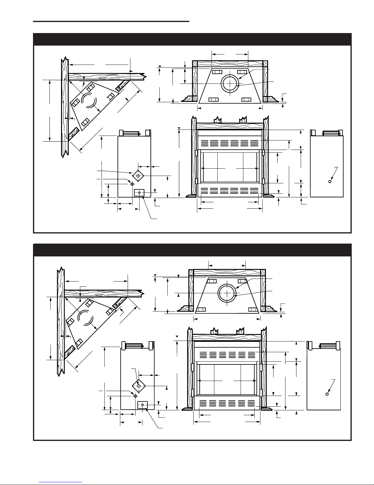
42"
(1067mm)
346"
(880mm)
46" (1168mm)
6"
6
" (16mm)
56O" (13mm)
56O"
6M"
(502mm)
56O" (64mm)
56O" (876mm)
56M"
(540mm)
6M"
(197mm)
Recessed
Nailing
Flange
11" Dia.
(279mm)
Rough Opening Width 47"
Rough
Opening
Height
Rough
Opening
Depth
Gas Line
Access
49" (1245mm)
49" (1245mm)
56O
" (1765mm)
6"
(187mm)
20"
(508mm)
56O"
(521mm)
" (711mm)
406M"
(1035mm)
6"
(372mm)
56M"
(337mm)
366"
(930mm)
3"
(76mm)
56O"
(241mm)
56O"
(191mm)
Outside
Air
Gas Line
Access
Electrical Access
*
(1194mm)
56M
" (895mm)
8" Dia.
(203mm)
1156O”
(292mm)
56M"
(540mm)
36"
(914mm)
346"
(880mm)
40" (1016mm)
6M"
(502mm)
56O"
(64mm)
56O" (876mm)
6M"
(197 mm)
11" Dia.
Rough Opening Width 41"
Rough
Opening
Height
Rough
Opening
Depth
456M"
(1162mm)
456M"
(1162mm)
6M"
(1645mm)
6"
(187 mm)
20"
(508mm)
"
(559mm)
406M"
(1035mm)
6"
(372mm)
56M"
(337mm)
366"
(930mm)
956O"
(241mm)
56O"
(191mm)
1/2"(13mm)
56O"
(13mm)
Outside Air
Gas Line
Access
Gas Line
Access
56O"
(521mm)
*
(1041mm)
(279mm)
3"
(76mm)
Electrical Access
8" Dia.
(203mm)
6" (822mm)
1/2”
1/2”
1156O”
(292 mm)
BC36MH Manufactured Housing Fireplace
* If elbows are offset to the back of the unit, chase depth will be 22⁵⁄₈” (575 mm).
Fig. 1 BC36MH specications and framing.
BC42MH Manufactured Housing Fireplace
*If elbows are offset to the back of the unit, chase depth will be 22⁵⁄₈" (575 mm).
Fig. 2 BC42MH Series specications and framing.
7412972
3
BC36MH, BC42MH Woodburning Fireplace
A
B
C
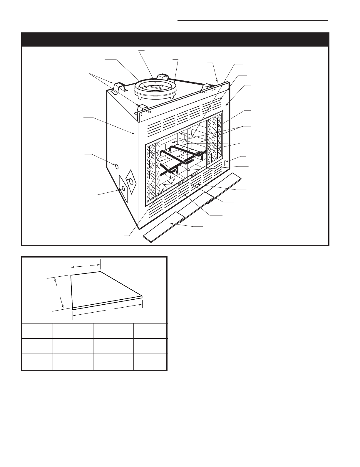
BCMH Parts Identication
Flue Collar
Damper
Outer Collar
Top Panel
Extension
Damper Control
Standoffs
(4 provided)
Surround
Facing Trim
Gas Line Access
(both sides)
Outside Air Access Cover Plate
Electrical Access
Glass Doors
Outlet Grille
Surround
Screen
Brick Sides and Back
Gas Line Access
(both sides)
Blower Switch
Hearth
Air Inlet
Grate
Firebox
Metal Safety Strip(s)
Shown Not in Place
(1,2 or 3 pieces)
Fig. 3 Parts of the BCMH replace.
Front Width Back Width Depth
A B C
BC36MH 33Z⁄v" 19⁵⁄₈" 15Z⁄v"
(845 mm) (499 mm) (387 mm)
BC42MH 39Z⁄v” 25⁵⁄₈” 15Z⁄v”
(997 mm) (651 mm) (387 mm)
Fig. 4 Hearth dimensions.
CAUTION: The structural integrity of the wall and ceil-
ing/roof of a manufactured home must be maintained.
It is not recommended to cut roof trusses or any other
structural member of the home. Consult local codes on
how to preserve the structural integrity of a manufactured home.
WARNING: Do not install in sleeping area.
4
FP1531
7412972
BC36MH, BC42MH Woodburning Fireplace
L
1
L
1
L
T
MODEL SK
2 WALL CHIMNEY
TOTAL
LENGTH
(LT)
INSTALLED
LENGTH
(L1)
SK81
SK818
SK83
SK84
11Z⁄₂
"
17Z⁄₂
"
35Z⁄₂
"
47Z⁄₂
"
10Z⁄₂
"
16Z⁄₂
"
34Z⁄₂
"
46Z⁄₂
"
Planning Information
Preplanning an installation is very important to ensure
safety and to save time and money. An installer must
predetermine where a replace will be set and how the
chimney system will be run.
Required Items
The following parts are required for installation of the
BCMH in a mobile home:
TABLE 1
Radiant Shield/Firestop SKRSFMH*
Chimney Flashing 8-6-12*
Chimney Top RLTSK8*
Hearth Extension EH2416 or equal
Storm Collar DB-8A*
(2) 36” Chimney Sections SK83*
(2) 18” Chimney Sections SK818*
Collars & Duct Assembly Included with replace
BCMHCK is the standard Chimney Kit package that includes items
marked with *
Note: Refer to Accessory Section on Page 18 for optional Chimney
Package and optional Chimney Top.
NOTE: When these replaces are properly assembled
with the above listed venting accessories, the installation complies with HUD’s Manufactured Home Construction and Safety Standards (3280.703, 3280.709g)
and Model Manufactured Home Installation Standards
(3285.505(f)).
Models BC36MH and BC42MH may also be installed
into a site-built or modular home when appropriate IRC,
IBC and/or local building codes are followed. In those
installations, neither an outside air kit nor the SKRSFMH Radiant Shield/Firestop may be required.
If you choose to install the MH model replace into a
site-built or modular home, any chimney components
available for conventional models BC36/42 may be
used.
The MH model replaces are supplied standard with
components that allow connection of a 6” outside fresh
air ex vent. If you choose to use these components to
install an outside air kit into a site-built or modular home
application, accessory termination kit Model AK6MH
may be used to complete the installation.
The replace must be spaced 1/2” (13 mm) from a
combustible back wall and 1/2” (13 mm) from a combustible side wall or support. Refer to Specications,
Page 3, Figure 1 and Air space Data, Figure 14, to be
sure the location selected for the replace provides for
clearance and framing restrictions.
Planning the Chimney Run
Determine how the chimney will be run, length of run
and chimney components required to complete the job.
Never install a chimney below minimum heights.
Remember, the replace may not be installed in a bedroom. It is not recommended to cut roof trusses. Consult the local codes on how to preserve the structural
integrity of the mobile home oor, wall and ceiling/roof.
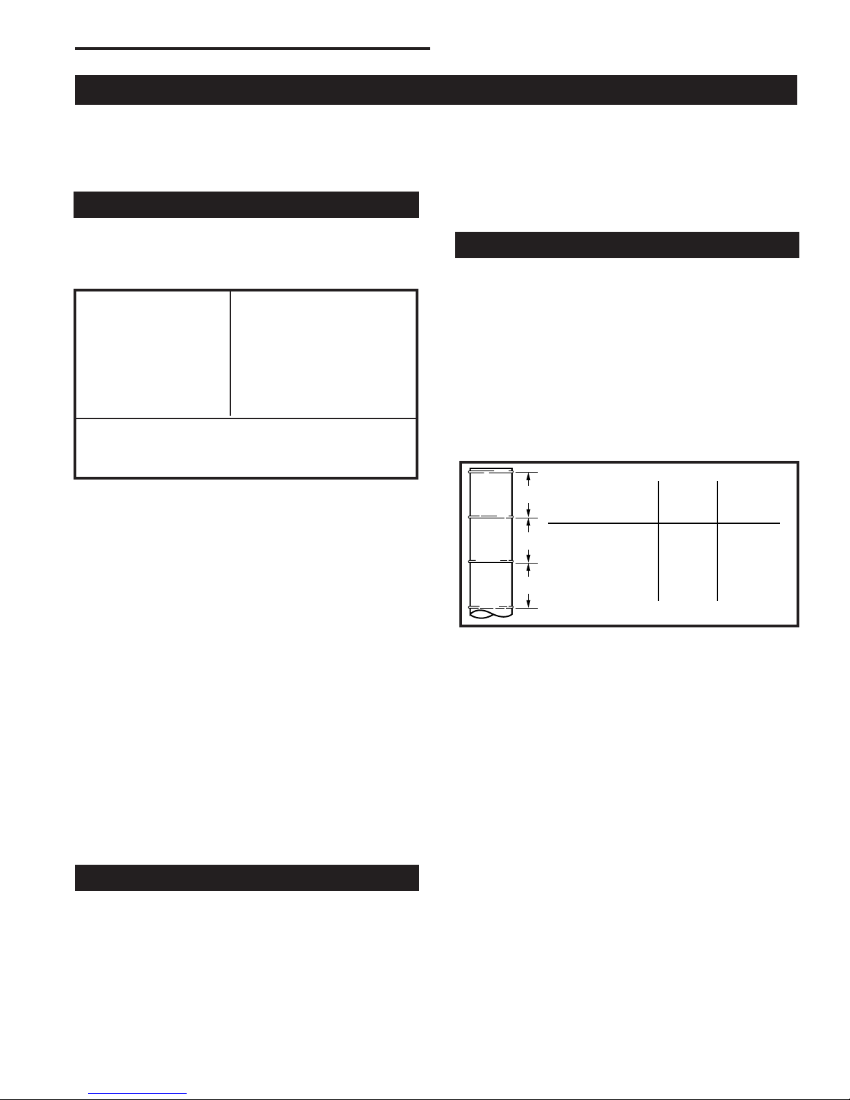
NOTE: The installed length of the chimney section is
less than its total length (except for the last section
installed), because of its overlap at joints. (Fig. 6)
FP288
Fig. 6 Installed lengths of chimney sections.
In planning a chimney system, it is important to know:
• The height of a chimney is measured from the hearth
to the exit point on the termination.
• A guy wire stabilizer is required for chimneys extending more than 6’ (1.8 m) above a roof line.
Mounting the Fireplace
A replace may only be mounted on the following surfaces:
• A at combustible surface
• A raised wooden platform
• A concrete block or other solid object placed beneath each of the four (4) corners
7412972
5
BC36MH, BC42MH Woodburning Fireplace
OFFSET
RISE
D
RISE
B
G
H
B
OFFSET
C
E
6 FT.
G
H
A
HEARTH
FLOOR
CHIMNEY
SECTION
CHIMNEY FLUE EXIT
ELBOW
30˚
OFFSET
ELBOW
30˚
OFFSET
ELBOW
30˚
RETURN
ELBOW
30˚
RETURN
ELBOW
SKCS8
SUPPORT
Example 1 Example 2 Example 3
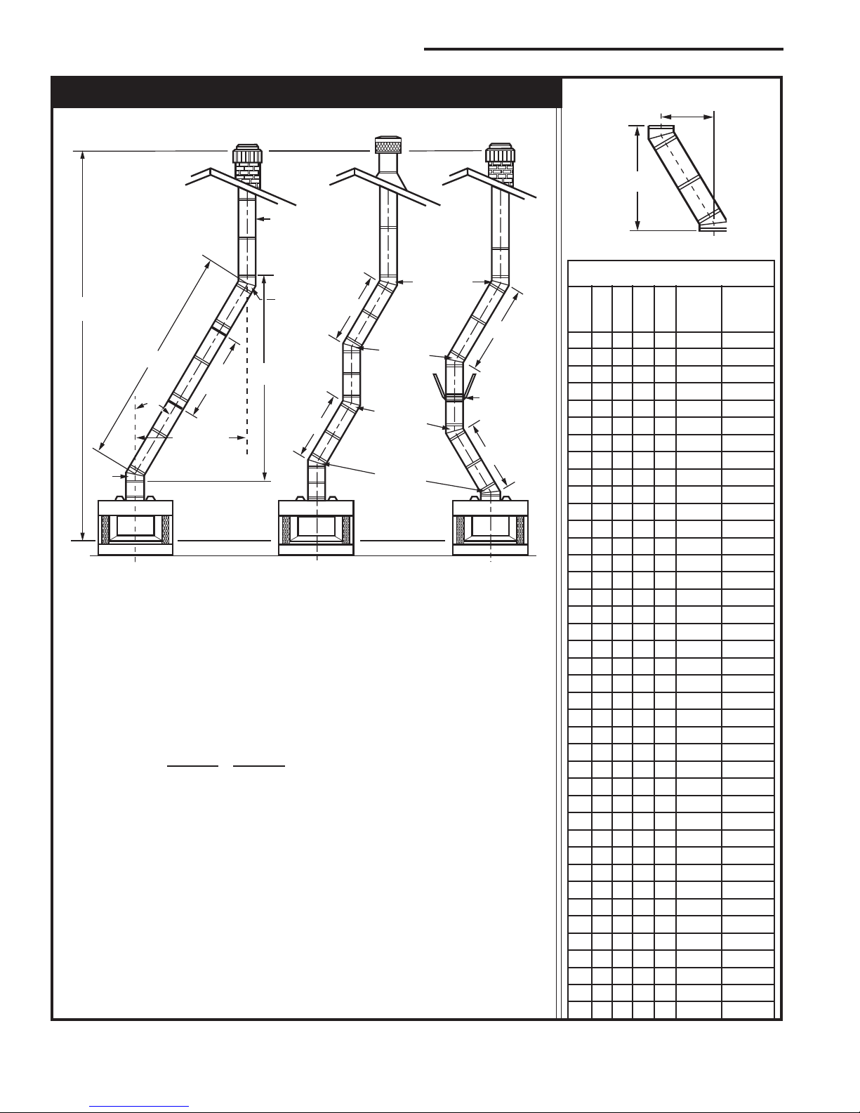
Chimney Requirements - Offset Installations
FP282
30° Elbow Offsets
Notes: G + H cannot exceed 20 feet.
Air space clearances: SK8 (2-wall = 1Z⁄₂" and "S" Series (3-wall) = 2"
Illustration Key
The following safety rules apply to
offset installations (letters correspond
with illustration above):
A. Height of the chimney is measured
from the hearth to the chimney exit.
BC36MH BC42MH
Maximum: 90'0" 90'0"
Minimum:
Without Elbows 12' 6" 12' 6"
With 2 Elbows* 14' 6" 14' 6"
With 4 Elbows* 21' 0" 21' 0"
B. Do not use more than 4 elbows per
chimney.
Attach the straps of the return (top)
elbow to a structural framing member.
The offset (rst) elbow of any pair does
not have straps.
Fig. 5 Chimney system requirements.
6
1'
0 0 0 0 0 3" 11"
1 0 0 0 0 8Z⁄v" 20"
0 1 0 0 0 11Z⁄v" 25Z⁄v"
2 0 0 0 0 13Z⁄₂" 29Z⁄v"
1 1 0 0 0 16Z⁄₂" 34Z⁄v"
0 0 1 0 0 20Z⁄v" 40³⁄v"
2 1 0 0 0 21³⁄v" 43Z⁄₂"
0 0 0 1 0 26Z⁄v" 51Z⁄v"
0 1 1 0 0 28Z⁄₂" 55Z⁄v"
1 0 0 1 0 31Z⁄₂" 60Z⁄v”
0 1 0 1 0 34Z⁄₂" 65Z⁄₂"
0 0 2 0 0 37Z⁄₂" 70³⁄v"
1 1 0 1 1 41Z⁄₂" 77³⁄v"
0 0 1 1 1 45" 83³⁄v"
FP269
C. The chimney cannot be more than 30°
(45° in Canada) from the vertical plane in
any installation*.
D. The maximum length of the angled run
of the total chimney system is 20 feet. (G
plus H cannot exceed 20 feet.)
E. A chimney support (Model SKCS8)
is required every 6 feet of angled run of
chimney. Chimney supports are required
for every 30 feet and 60 feet (SK8 pipe)
or 20 feet and 40 feet (3-wall pipe) of vertical chimney height above the hearth.
Determine the offset distance of your
chimney arrangement from the centerline
of the replace to the centerline of the
chimney where it is to pass through the
rst ceiling.
NOTE: This offset distance may not be
your full offset distance. See Examples 2
and 3.
0 1 2 0 1 47Z⁄v" 87Z⁄₂"
0 0 0 2 1 51" 94"
0 1 1 1 1 53Z⁄v" 98"
0 0 3 0 1 56Z⁄v" 103Z⁄v"
0 1 0 2 1 59Z⁄v" 108Z⁄₂"
0 0 2 1 1 62Z⁄v" 113Z⁄₂"
0 1 3 0 1 64Z⁄₂" 117Z⁄₂"
0 0 1 2 1 68Z⁄v" 124"
0 1 2 1 1 70Z⁄₂" 128"
0 0 0 3 1 74Z⁄v" 134Z⁄₂"
0 1 1 2 2 78" 140³⁄v"
0 0 3 1 2 81" 146"
0 1 0 3 2 84" 151Z⁄v"
0 0 2 2 2 87" 156Z⁄₂"
0 1 3 1 2 89Z⁄v" 160Z⁄v"
0 0 1 3 2 93" 166³⁄v"
0 1 2 2 2 95Z⁄v" 170³⁄v"
0 0 0 4 2 99Z⁄v" 177³⁄v"
0 1 1 3 2 101Z⁄v" 181³⁄v"
0 0 3 2 2 104Z⁄v" 186Z⁄v"
0 1 0 4 2 107Z⁄v" 191Z⁄₂"
0 0 2 3 2 110Z⁄v" 196³⁄v"
0 1 3 2 3 114" 203Z⁄v"
0 0 1 4 3 117³⁄v" 209³⁄v"
0 1 2 3 3 120" 213Z⁄₂"
0 0 0 5 3 123³⁄v" 220"
1¹⁄₂'
3' 4'
Offset
Chimney
Support
Rise
7412972
BC36MH, BC42MH Woodburning Fireplace
2' Min.
2' Min.
3'
Min.
0 To 10'
3'
Min.
0 To 10'
Reference
Point
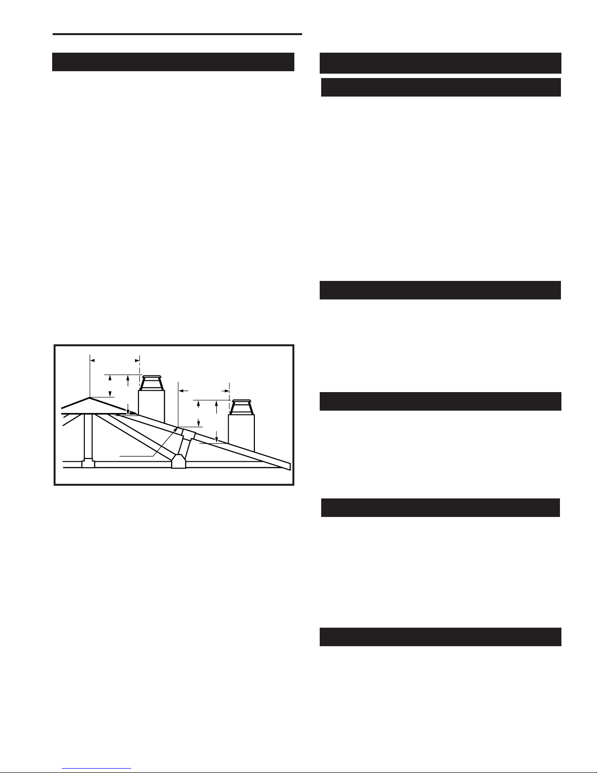
The Ten Foot Rule
Major U.S. building codes specify a minimum chimney
height above the roof top. The “Ten Foot Rule” is a re
safety rule and not a draft rule. It is recommended that
you always meet or exceed the “Ten Foot Rule”. (Fig.
7)
The key points of the “Ten Foot Rule” are:
1. If the horizontal distance from the chimney to the
peak of the roof is 10’ (3 m) or less, the top of the
chimney must be at least 2’ (610 mm) above the
peak of the roof, but never less than 3’ (914 mm)
in height above the highest point where it passes
through the roof.
2. If a horizontal distance from the chimney to the
peak of the roof is more than 10’ (3 m), a chimney
height reference point is established on the surface
of the roof a distance of 10’ (3 m) from the chimney
in a horizontal plane. The top of the chimney must
be at least 2’ (610 mm) above the reference point,
but never less than 3’ (914 mm) in height above the
highest point where it passes through the roof.
Installation
Install Electrical Connection
CAUTION: All wiring shall be done by a qualied
electrician and shall be in compliance with all local,
city and state building codes.
IMPORTANT: To prevent electrical shock, the power for
the home must be disabled. This can be accomplished
by positioning the circuit breaker to off.
The BCMH is equipped with a factory installed FK-12
fan and the EB1 junction box. The fan requires 120V
AC, 60Hz wiring to be run to the left side of the unit.
This should be completed before the replace is nished.
NOTE: Check local building codes to determine if a
junction box is required at the romex pigtail/house wire
connection.
Chimney Setup
Since you have already preplanned the chimney run,
you should know exactly how the installation is to be accomplished - how much pipe is required and the type of
termination to be used.
CAUTION: Report to your dealer any parts damaged
in shipment, specically check the end connection
of chimney sections.
Fig. 7 Ten Foot Rule illustration.
7412972
AC246
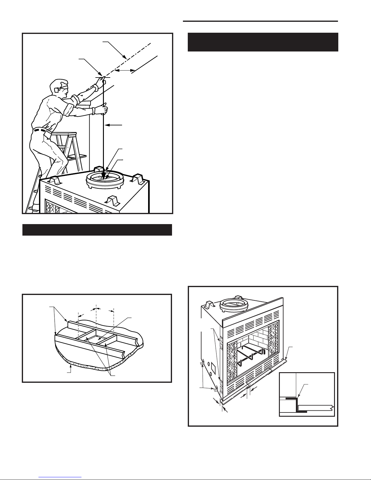
Straight-Up Chimney Installation
To mark the centerline of the ue, put the replace in
nal position and measure out from the wall 7⁷⁄₈” (200
mm). Mark a spot on the ceiling directly above the
replace. Draw a line parallel to the back wall through
this mark. (Fig. 8) Using a plumb bob positioned directly
over centerpoint of replace ue collar, mark the ceiling
to establish the chimney centerpoint. (Fig. 8)
Ceiling Chimney Hole
Drive a nail up through the ceiling at the marked chimney centerpoint. Check where the hole will be cut for
ceiling joists and any other obstructions such as wiring
or plumbing runs. If necessary, reposition the chimney
and/or the replace to better accommodate these joists
and/or obstructions. Remember: it is not recommended
to cut roof trusses, as the structural integrity of the
mobile home oor, wall and ceiling/roof must be maintained.
Cutting the Hole
Cover replace collar opening and cut proper sized
chimney hole in ceiling. (Fig. 9)
7
BC36MH, BC42MH Woodburning Fireplace
56O"
(38 mm)
Chimney Centerline
Actual Centerpoint
7⁷⁄₈”
(200mm)
Plumb Line
Plumb Bob
Imaginary Centerpoint
FP556MH
Fig. 8 Locate centerline of chimney with plumb line.
Framing the Ceiling Hole
Frame the ceiling chimney hole as shown in Figure 9. It
is good practice to use framing lumber that is the same
size as the ceiling joists.
The inside dimension of the frame must be the same
as the hole size in order to provide the required 1Z⁄₂”
(38 mm) air space between the outside diameter of the
chimney and the edges of the framed ceiling hole.
Positioning, Safety Strips,
Securing The Fireplace
Slide replace into position.
Lift the replace front slightly and slide the metal safety
strips under front bottom edge about 1Z⁄₂” (38 mm),
allowing the remainder to extend in front of rebox.
Overlap strips at least 1/2” (13 mm) to provide a positive joint. (Flat safety strips are packed with replace)
(Fig. 10)
Safety strips are used to ensure that any combustible
materials in front of the replace are protected even
though a noncombustible hearth extension is required.
If replace is to be elevated above the oor, a “Z”
shaped metal safety strip must be fabricated and used
to protect combustible surfaces in front of the replace.
This “Z” shaped safety strip is not provided but must
be fabricated of metal with each horizontal leg at least
1Z⁄₂ inches wide and equal in length to the metal strips
provided with the replace.
NOTE: Safety strips are not required over noncombustible oors where all supports at the base of the replace
are noncombustible.
To prevent shifting of the replace, nail down straps and
nailing anges are supplied on the replace.
Secure replace to oor with four (4) nail down straps
located at the bottom of either side of the replace.
Secure the replace to the vertical framing studs using
the appropriate nailing anges on either side of the
replace front face. (Fig. 10)
Existing Roof
Joists
FP551A
Fig. 9 Typical frame for ceiling chimney hole.
Ceiling
14Z⁄₂”
(368mm)
14Z⁄₂”
(368mm)
New Framing Members
8
Chimney Hole
Nailing
Flanges
Nail
Down
Straps
Fig. 10 Safety strip installation.
1/2” (13mm)
Min. Overlap
Metal Safety Strips
(1, 2 or 3 pieces)
Fireplace
Platform
(not included)
Hearth Ext.
“Z” Safety
Strip
FP557MH
7412972
 Loading...