

Vermont Castings AVFL42NTSC, AVFL42PTSC Installation & Operating Instructions Manual
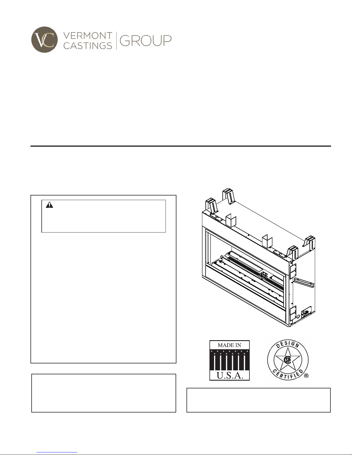
AVFL Vent Free Fireplace System
Installation & Operating Instructions
Models: AVFL42NTSC & AVFL42PTSC
WARNING: If the information in this
manual is not followed exactly, a fi re or
explosion may result causing property
damage, personal injury or loss of life.
• Do not store or use gasoline or other
fl ammable vapors and liquids in the
vicinity of this or any other appliance.
• WHAT TO DO IF YOU SMELL GAS
– Do not try to light any appliance.
– Do not touch any electrical switch; do
not use any phone in your building.
– Leave the buildling immediately.
– Immediately call your gas supplier from
a neighbor's phone. Follow the gas
supplier's instructions.
– If you cannot reach your gas supplier,
call the fi re department.
• Installation and service must be performed
by a qualifi ed installer, service agency or
the gas supplier.
This is an unvented gas-fi red heater. It uses air
(oxygen) from the room in which it is installed.
Provisions for adequate combustion and ventil-
ation air must be provided. Refer to Page 7.
INSTALLER: Leave this manual with the appliance.
CONSUMER: Retain this manual for future
reference.
20305467 5/14 Rev. 1

AVFL Vent Free Fireplace
CONTENTS
Thank you and congratulations on your purchase of an
Vermont Castings Group Fireplace.
PLEASE READ THE INSTALLATION AND OPERATION INSTRUCTIONS BEFORE USING THE APPLIANCE!
IMPORTANT: Read all instructions and warnings carefully before starting installation.
Failure to follow these instructions may result in a possible fi re hazard and will void the warranty.
Important Safety Information .................................... 3
Building Code Information .........................................4
Product Features .........................................................5
AVFL42 Controls ...................................................... 5
Gas Specifi cations & Orifi ce Size ............................. 5
Gas Pressures .......................................................... 5
Fireplace and Framing Dimensions .......................... 6
Pre-installation Information ........................................7
Getting Started .........................................................7
What You Will Need .................................................. 7
Planning the Installation ...........................................7
Adequate Combustion and Ventilation Air ................ 7
Fireplace Location .................................................... 8
Clearances & Height Requirements ......................... 9
Fireplace Installation .................................................10
Secure Fireplace to Framing .................................. 10
Finishing Material ................................................... 10
Noncombustible Facing Installation ...........................................10
Connect the Gas .................................................... 11
Check Gas Pressure ..............................................12
Electrical Installation.................................................13
Wiring Junction Box ............................................... 13
Signature Command® Wiring Diagram ................... 14
Final Installation ........................................................15
Installation of Air Defl ection Glass .......................... 15
Glass Only Placement ............................................ 15
Glass & Optional Stone Kit Placement ................... 15
Placement of Optional Logs ...................................16
Operating Instructions ..............................................17
For Your Safety Read Before Lighting .................... 17
Turning On Unit ...................................................... 18
To Turn Off Gas to Appliance .................................. 18
Signature Command® System Operation ................19
Features ................................................................. 19
Battery Installation .................................................. 19
System Confi guration/Setup ................................... 19
Cold Climate Option ...............................................19
Functions/Operation ............................................... 21
Touch Screen Remote Control Operation ............... 22
Troubleshooting ...................................................... 27
Maintenance and Cleaning .......................................28
Flame Appearance ................................................. 28
Check the Pilot Flame ............................................28
Check Burner Flame Appearance .......................... 28
Cleaning and Servicing .......................................... 29
Operating Information ............................................. 29
Troubleshooting ........................................................30
Signature Command
Replacement Parts .................................................... 32
Firebox ................................................................... 32
Logs ........................................................................ 33
Stones .................................................................... 33
Signature Command® System ................................ 34
Optional Accessories ................................................ 35
Limited Lifetime Warranty Policy .............................39
®
System ................................ 31
2
20305467

IMPORTANT SAFETY INFORMATION
AVFL Vent Free Fireplace
INSTALLER
Please leave these instructions with the appliance.
OWNER
Please retain these instructions for future reference
• Any change to this heater or its controls can be dangerous.
• Improper installation or use of the heater can cause serious injury or death from fi re, burns,
explosion or carbon monoxide poisoning.
• Do not allow fans to blow directly into the fi replace. A void any drafts that alter burner fl ame
patterns.
WARNING
• Do not use a blower insert, heat exchanger insert or other accessory, not approved for use
with this heater where applicable.
1. Due to high temperatures, the appliance should be
located out of traffi c and away from furniture and
draperies.
2. Children and adults should be alerted to the hazard
of high surface temperature and should stay away
to avoid burns or clothing ignition.
3. Young children should be carefully supervised when
they are in the same room with the appliance.
4. Do not place clothing or other fl ammable material
on or near the appliance.
5. Any safety screen or guard removed for servicing
an appliance, must be replaced prior to operating
the heater.
6. Installation and repair should be done by a qualifi ed service person. To prevent malfunction and/or
sooting, an unvented gas heater should be cleaned
before use and at least annually by a professional
service person. More frequent cleaning may be
required due to excessive lint from carpeting,
bedding materials, etc. It is imperative that control
compartments, burners and circulating air passageways be kept clean.
7. WARNING: Any change to this heater or its controls
can be dangerous.
8. Unvented gas heaters are a supplemental zone
heater. They are not intended to be the primary
heating appliance.
9. CARBON MONOXIDE POISONING: Early signs of
carbon monoxide poisoning are similar to the fl u with
headaches, dizziness and/or nausea. If you have these
signs, obtain fresh air immediately. Have the heater
serviced as it may not be operating properly.
10. The installation must conform with local codes or, in
the absence of local codes, with the National Fuel
Gas Code, ANSI Z223.l/NFPA54.
11. This unit complies with ANSI Z21.11.2 Unvented
Heaters, latest edition.
12. Do not install the heaters in a bathroom or bedroom.
13. Correct installation of the ceramic fi ber logs, proper
location of the heater, and annual cleaning are necessary to avoid potential problems with sooting. Sooting,
resulting from improper installation or operation, can
settle on surfaces outside the fi replace. Refer to log
placement instructions for proper installation.
14. Avoid any drafts that alter burner fl ame patterns. Do not
allow fans to blow directly into fi replace. Do not place
a blower inside burn area of fi rebox. Ceiling fans may
create drafts that alter burner fl ame patterns. Sooting
and improper burning will occur.
15. Caution: Candles, incense, oil lamps, etc. produce
combustion byproducts including soot. Vent-free
appliances will not fi lter or clean soot produced by
these types of products. In addition, the smoke and/
or aromatics (scents) may be reburned in the vent-free
appliance which can produce odors. It is recommended
to minimize the use of candles, incense, etc. while the
vent-free appliance is in operation.
16. This is an unvented gas-fired heater. It uses air
(oxygen) from the room in which it is installed. Provisions for adequate combustion and ventilation air must
be provided. Refer to Page 7.
17. This heater shall not be installed in a room or space
unless the required volume of indoor combustion air is
provided by the method described in the National Fuel
Gas Code, ANSI Z223.1/NFPA 54, the International
Fuel Gas Code or applicable local codes.
18. Keep room area clear and free from combustible materials, gasoline and other fl ammable vapors and liquids.
19. Unvented gas heaters emit moisture into the living
area. In most homes of average construction, this
does not pose a problem. In houses of extremely
tight construction, additional mechanical ventilation is
recommended.
20. During manufacturing, fabricating and shipping, various
components of this appliance are treated with certain
oils, fi lms or bonding agents. These chemicals are not
.
20305467
3

AVFL Vent Free Fireplace
harmful but may produce annoying smoke and smells
as they are burned off during the initial operation of the
appliance; possibly causing headaches or eye or lung
irritation. This is a normal and temporary occurrence.
The initial break-in operation should last two to three
hours with the burner at the highest setting. Provide
maximum ventilation by opening windows or doors to
allow odors to dissipate. Any odors remaining after this
initial break-in period will be slight and will disappear
with continued use.
21. Input ratings are shown in BTU per hour and are for
elevations up to 2,000 feet. For elevations above 2,000
feet, input ratings should be reduced 4 percent for each
1,000 feet above sea level. Refer to the National Fuel
Gas Code.
22. The appliance and its appliance main gas valve must
be disconnected from the gas supply piping system
during any pressure testing of that system at test
pressures in excess of
23. The appliance must be isolated from gas supply piping
system by closing its equipment shutoff valve during
any pressure testing of the gas supply piping system at
test pressures equal to or less than 1⁄2 psig (3.5 kPa).
24. Do not use this room heater if any part has been under
water. Immediately call a qualifi ed service technician
to inspect the room heater and to replace any part of
the control system and any gas control which has been
under water.
25. Never burn solid fuels in a fi replace where a unvented
room heater is installed.
1
⁄2 psig (3.5 kPa).
IMPORTANT SAFETY INFORMATION
This appliance may be installed in an aftermarket, permanently located, manufactured
(mobile) home, where not prohibited by local
codes.
This appliance is only for use with the type of
gas indicated on the rating plate. This appliance
is not convertible for use with other gases.
BUILDING CODE INFORMATION
Adhere to all local codes or, in their absence, the latest
edition of THE NATIONAL FUEL GAS CODE ANSI Z223.1
or NFPA54 which can be obtained from:
American National Standards Institute, Inc.
1430 Broadway
New York, NY 10018
or
National Fire Protection Association, Inc.
Batterymarch Park
Quincy, MA 02269
4
20305467
PRODUCT FEATURES
AVFL Vent Free Fireplace
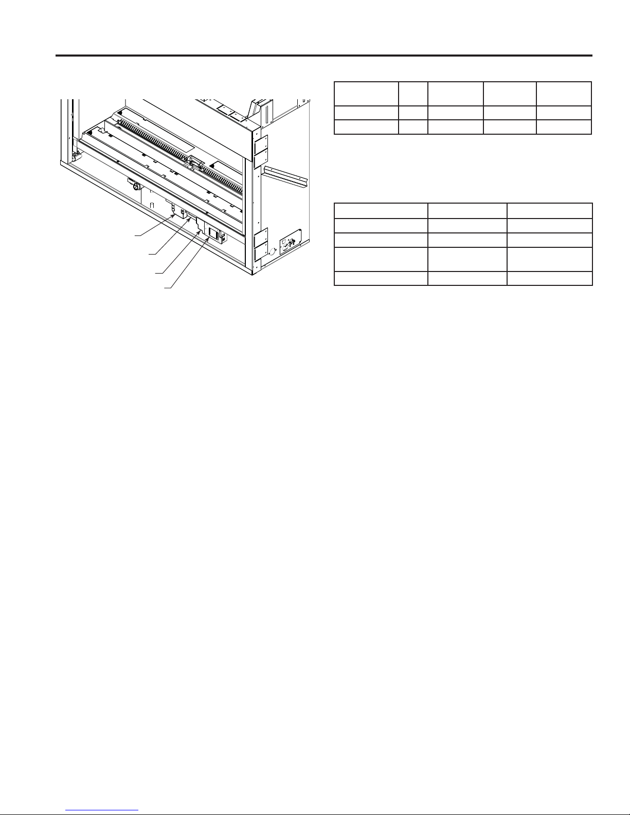
AVFL42 CONTROLS
Thermocouple
Module
Command Center
Control Board
AC Module
Figure 1 –
AVFL42 Controls (Control Access Door Shown Open)
FP3020
GAS SPECIFICATIONS & ORIFICE SIZE
MODEL FUEL
AVFL42NTSC NAT. 37,000 24,500 2.20 mm
AVFL42PTSC LP. 36,000 28,500 #55
MAX. INPUT
(BTU/h)
NOTE: For LP models an external regulator is required
to reduce supply pressure to a maximum of 13" w.c.
MIN. INPUT
(BTU/h)
ORIFICE
SIZE
GAS PRESSURES
NATURAL PROPANE (LP)
Inlet Minimum 5.0" w.c. 11.0" w.c.
Inlet Maximum 10.5" w.c. 13.0" w.c.
Regulator Pressure
Setting
Pilot Regulator 3.5" w.c. —
3.5" w.c. 10" w.c.
20305467
5
AVFL Vent Free Fireplace
48C\v" (1238 mm)
34Z\x"
(876 mm)
" (13 mm)
1/2
or 5/8
" (16 mm)
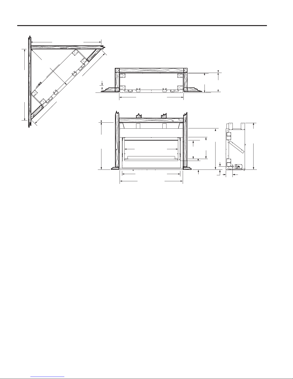
FIREPLACE AND FRAMING DIMENSIONS
Minimum
Rough
Depth
13"
(330 mm)
13 1/2"
(343 mm)
48C\v" (1238 mm)
68ZB\zn" (1751 mm)
Figure 2 –
Fireplace and Framing Dimensions
Minimum
Rough
Height
32"
(813 mm)
44" (1118 mm)
Rough Opening Width
37 1/2" (953 mm)
39 3/4" (1010 mm)
43" (1092 mm)
(386 mm)
13 1/4"
(337 mm)
6 1/16"
(154 mm)
15 3/16"
2 1/4"
(57 mm)
28"
(711 mm)
(813 mm)
4 5/8"
(118 mm)
32"
6
20305467

PRE-INSTALLATION INFORMATION
AVFL Vent Free Fireplace
GETTING STARTED
Check your packing list to verify that all listed parts have
been received. You should have the following:
• Unvented gas heater
• Two (2) anchoring screws
• Installation/operating instructions
• 5" non-combustible board
• 2" x 32" defl ector glass
• Two (2) bags fi reglass
• Twelve (12) 20 watt bulbs
• One (1) 100 watt bulb
• TSFSC remote control
Carefully inspect the contents for shipping damage. If any
parts are missing or damaged, immediately inform the
dealer from whom you purchased the appliance. Do not
attempt to install any part of the appliance unless you
have all parts in good condition.
WHAT YOU WILL NEED
You must have the following items available before proceeding with installation:
• External regulator (for propane/LPG only)
• Manual shutoff valve
• Piping which complies with local codes
• Sediment trap
• Phillips head screwdriver
• Tee joint.
• Pipe sealant approved for use with propane/LPG
(Resistant to sulfur compounds)
• Pipe wrench
Do not install the heater:
• Where curtains, furniture, clothing, or
other fl ammable objects are less than
36" from the front of the heater.
• In high traffi c areas.
WARNING
• In windy or drafty areas.
Gloves are recommended when handling
ceramic fi ber logs to prevent skin irritation
from loose fi bers. Logs are fragile — handle
with care.
WARNING
PLANNING THE INSTALLATION
In planning the installation for the fi replace it is necessary
to determine where the unit is to be installed and whether
optional accessories are desired. Gas supply piping should
also be planned. The following steps represent the normal
sequence of installation. Each installation is unique, however, and might require a different sequence.
1. Position fi replace in desired location. Refer to the Fire-
place Location (page 8, Figure 3) and Clearances and
Height Requirements (page 9, Figures 4 and 5) sections
and Fireplace and Framing Dimensions (page 6, Figure
2) illustration found in this manual.
NOTE: Be sure all packing material has been removed
from under the unit.
2. Install following the instructions found in this manual.
3. Field wire main power supply to junction box. Refer to
the Electrical Installation section (page 13). (Electrical
connections should only be performed by an experienced, licensed certifi ed service person).
4. Plumb gas line. Refer to the Connect the Gas (page
11, Figure 7) section found in this manual. (Gas
connections should only be performed by an experienced, licensed/certifi ed service person).
5. Complete fi nish wall material and/or surround.
ADEQUATE COMBUSTION AND VENTILATION AIR
This heater shall not be installed in a confi ned space or
unusually tight construction unless provisions are provided
for adequate combustion and ventilation air.
The National Fuel Gas Code, (ANSI Z223.1/NFPA54),
defi nes a confi ned space as a space whose volume is less
than 50 cubic feet per 1,000 BTU per hour (4.8m3 per kw) of
the aggregate input rating of all appliances installed in that
pace, and an unconfi ned space as a space whose volume
is not less than 50 cubic feet per 1,000 BTU per hour (4.8
m3 per kw) of the aggregate input rating of all appliances
installed in that space. Rooms communicating directly with
the space in which the appliances are installed, through
openings not furnished with doors, are considered a part
of a confi ned space.
Unusually tight construction is defi ned as construction
where:
a. walls and ceilings exposed to the outside atmosphere
have a continuous water vapor retarder with a rating of
1 perm (6 x 10
gasketed or sealed, and
b. weather stripping has been added on openable windows
and doors, and
11
kg per pa/sec-m2) or less with openings
20305467
7
AVFL Vent Free Fireplace
PRE-INSTALLATION INFORMATION
c. caulking or sealants are applied to areas such as joints
around window and door frames, between sole plates
and fl oors, between wall-ceiling joints, between wall
panels, at penetrations for plumbing, electrical and gas
lines and other openings.
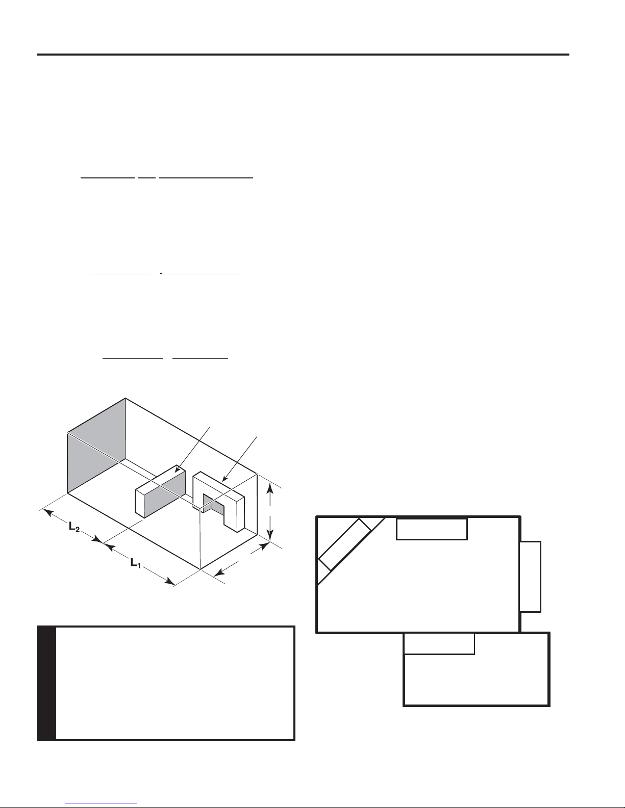
The following formula can be used to determine the maximum heater rating per the defi nition of unconfi ned space:
BTU/Hr = (L
Consider two connecting rooms with an open area
between, with the following dimensions:
L1 = 151/2 Ft., L2 = 12 Ft., W = 12 Ft., H = 8 Ft.
BTU/Hr = (151/2 + 12) x (12) x (8)
If there were a door between the two rooms the calculation
would be based only on the room with the heater.
BTU/Hr = (151/2) x (12) x (8)
1 + L2) Ft x (W) Ft x (H) Ft
50
50
50
Counter
Fireplace
FIREPLACE LOCATION
This unvented gas heater requires no outside venting and
burns cleanly and effi ciency. As a zero-clearance unvented
gas heater, it can be installed against (or recessed into)
any wall that is accessible to a gas line.
Carefully select the best location for installation of your
unvented fi replace. The following factors should be taken
into consideration.
• Clearance to side wall, ceiling, woodwork and window
or other combustibles. Refer to Clearance and Height
Requirements section on Page 9. Minimum clearances
to combustibles must be maintained.
• Location must not be affected by drafts caused by
kitchen exhaust fans, ceiling fans, return air registers
for forced air furnaces / air conditioners, windows or
doors.
• Installation must provide adequate ventilation and
combustion air.
• DO NOT INSTALL THIS MODEL IN A BEDROOM
OR BATHROOM.
• Location should be out of high traffi c areas and
away from furniture and draperies due to heat from
fi rebox.
• Never obstruct the front opening of the unvented fi re-
place or restrict the fl ow of combustion and ventilation
air.
• Minimize modifi cations to existing construction. Refer
to Figure 3 below for location suggestions.
• Do not install in the vicinity where gasoline or other
fl ammable liquids may be stored. The unvented fi re-
box must be kept clear and free from the combustible
materials.
If the area in which the heater may be
operated does not meet the required volume
for indoor combustion air, combustion and
ventilation air shall be provided by one
of the methods described in the National
Fuel Gas Code, ANSI Z223.1/NFPA 54, the
WARNING
International Fuel Gas Code or applicable
local codes.
8
W
H
Figure 3 –
Possible Fireplace Locations
FP3029
20305467
PRE-INSTALLATION INFORMATION
AVFL Vent Free Fireplace
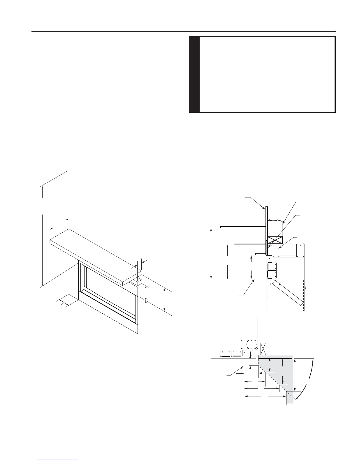
CLEARANCES AND HEIGHT REQUIREMENTS
Ensure that minimum clearances shown in Figures 4 and
5 are maintained. Left and right clearances are determined
when facing the front of the fi rebox.
Follow these instructions carefully to ensure safe installation. Failure to follow these requirements may create a
fi re hazard.
Sidewall Clearances — The clearance from the inside of
the appliance to any combustible adjacent wall should not
be less than 6". Figure 4
Ceiling Clearance — The ceiling or any other combustible
material must be at least 36" from the fi rebox opening.
Figure 4
Back Wall Clearance — The appliance may be placed
against a combustible back wall.
36" Minimum
From Opening
" Max.
12
Depth
The dimensions shown in Figures 4 and
5 are minimum clearances to maintain
when installing this heater. Left and right
clearances are determined when facing the
front of the heater.
Follow these instructions carefully to
WARNING
ensure safe installation. Failure to follow
instructions exactly can create a fire
hazard.
Floor Clearance — The fi replace may be installed directly
on a combustible fl oor or a raised platform of an appropriate
height. Do not place fi replace on carpeting, vinyl, tile or
other soft fl oor coverings. It may, however, be placed on fl at
wood, plywood, particle board or other hard surfaces. Be
sure fi replace rests on a solid continuous fl oor or platform
with appropriate framing for support so that no cold air can
enter from under the fi rebox.
Mantel clearances — Must meet the clearance requirements detailed in Figures 4 and 5.
Wall
12"
Stud
Insulation
Board
" Min.
6
Figure 4 –
Sidewall and Ceiling Clearances
21/2" Max
Depth
28" Min.
From Opening
18
" Min.
From Opening
FP3006
28"
Top of Fireplace
Opening
SIDE VIEW
Fireplace
Opening
TOP VIEW
23"
6"
18"
1"
256O"
3"
Standoff
1
2
/2"
FP3007
156O"
356O"
456O"
45°
5"
6"
FP3008
20305467
Figure 5 –
Mantel Clearances
9
AVFL Vent Free Fireplace
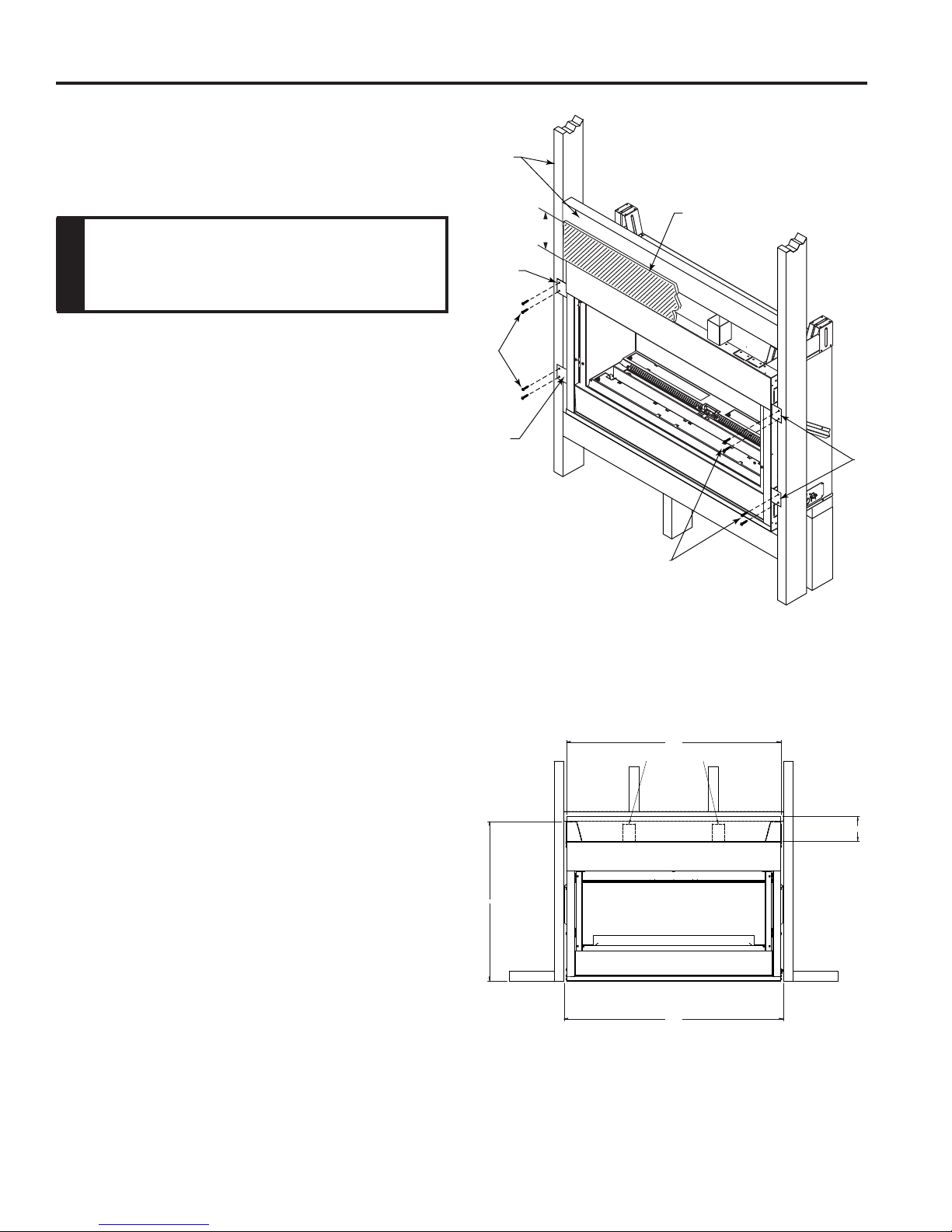
SECURE FIREPLACE TO FRAMING
FIREPLACE INSTALLATION
The fi replace must be secured to the framing studs as
shown in Figure 6. Use four (4) screws to attach fi replace
1
to framing. The side nailing fl anges are
⁄2" or 5⁄8" to accom-
modate different wall thickness.
Never install combustible materials over
front face of fi replace.
NOTE
FINISHING MATERIAL
NOTE: Any remote wiring (i.e. remote control, wall
switch), must be done prior to fi nal fi nishing to avoid costly
reconstruction.
Only noncombustible materials (i.e. brick, tile, slate, steel,
or other materials with a UL fi re rating of Zero) may be
used to cover the black painted face of the appliance. It is
permissible to bring combustible wall board to the top of
the standoffs on the top and to the wall board stand-offs
on the sides of the unit. A 300°F minimum adhesive may
be used to attach facing materials to the black surface. If
joints between the fi nished wall and the fi replace surround
are sealed, a 300°F minimum sealant material (General
Electric RTV103 or equivalent) must be used.
NOTE: Fireplace may be installed on top of framing or
platform constructed of combustible materials which do
not protrude beyond the face.
Framing
Members
5”
Nailing
Flange
Screws
Nailing
Flange
Screws
Figure 6 –
Secure Fireplace to Framing Studs
Noncombustible Material
FP3009
Nailing
Flange
NONCOMBUSTIBLE FACING INSTALLATION
CAUTION: The noncombustible wall board supplied with
this unit can be damaged if dropped or struck. Handle
with care.
1. Using drywall screws secure noncombustible board to
the two brackets on top of unit. IMPORTANT: To avoid
cracking the board, pre-drill holes prior to securing to the
unit/framing.
2. Wipe any debris or dust from the noncombustible board
and drywall.
3. It is highly recommended to prime the facing using a
quality primer prior to taping and mudding. This will
ensure proper adhesion of both the tape and mud. The
supplied board is very porous.
4. Tape the seams using a mesh type tape.
5. Mud seams as normal. We recommend using a product
call Durabond high strength compound for the fi rst coat.
This product can be purchased at any hardware store.
Follow manufacturer's recommendations for curing the
mud. NOTE: Depending upon the fi nal fi nishing method,
use a minimum rated 300 degree sealant, drywall compound or thin set to seal the side and top joints.
6. Prime wall for a second time for proper adhesion of paint.
43"
MOUNTING POINTS
32"
44"
Figure 6A –
Noncombustible facing installation
5"
10
20305467
FIREPLACE INSTALLATION
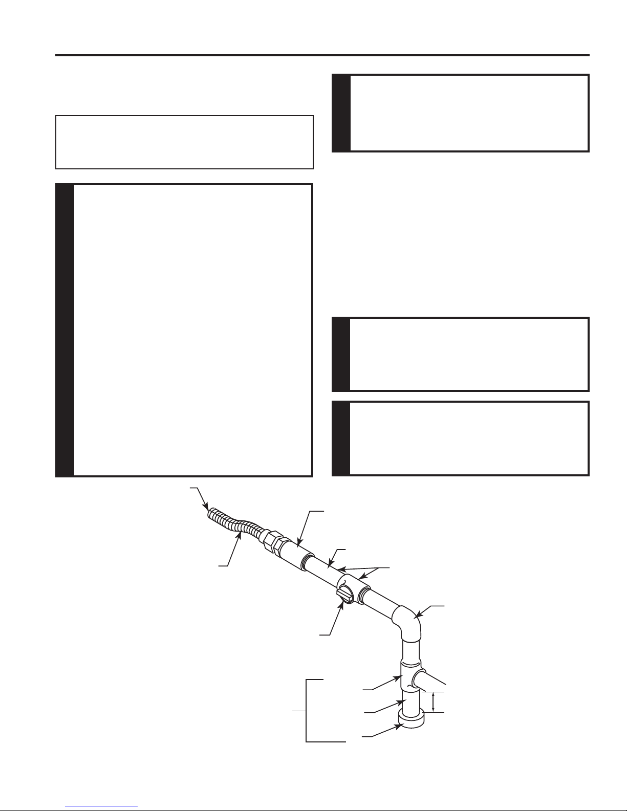
CONNECT THE GAS
NOTICE: A qualifi ed gas appliance installer must connect
the heater to the gas supply. Consult all local codes.
WARNING
This appliance is equipped for either natural or
propane gas. Field conversion is not permitted.
Use new black iron or steel pipe. Internally
tinned copper or copper tubing can be
used per National Fuel Code, section 2.6.3,
providing gas meets hydrogen sulfi de limits,
and where permitted by local codes. Gas
piping system must be sized to provide
minimum inlet pressure (Listed on Data
Plate) at the maximum fl ow rate (BTU/hr).
Undue pressure loss will occur if the pipe
is too small.
A manual shutoff valve must be installed
upstream of the appliance. Union tee
WARNING
and plugged 1⁄8" NPT pressure tapping
point should be installed upstream of the
appliance. Figure 7
A sediment trap should be installed upstream
to prevent moisture and contaminants from
passing through the pipe to appliance
controls and burners. Failure to do so
could prevent the appliance from operating
reliable. Figure 7
AVFL Vent Free Fireplace
CHECK GAS TYPE: The gas supply must
be the same as stated on the heater’s rating
plate. If the gas supply is different, DO NOT
INST ALL THE HEA TER. Contact your dealer
WARNING
for the correct model.
IMPORTANT: Loosen the pipe adapter on the fl ex tube
before installing to the system piping.
Always use an external regulator for all propane/LPG heaters only, to reduce the supply tank pressure to a maximum
of 13" w.c. This is in addition to the internal regulator in the
heater valve.
When tightening the joint to the valve, hold the valve
securely to prevent movement.
Test all gas joints from the gas meter to the heater valve for
leaks using a gas analyzer or soap and water solution after
completing connection. DO NOT USE AN OPEN FLAME.
Connecting directly to an unregulated
propane/LP tank can cause an
explosion.
WARNING
DO NOT USE OPEN FLAME TO CHECK
FOR GAS LEAKS.
WARNING
Figure 7 –
Gas Connection
20305467
To Fireplace
Stainless
Flexible Tube
Manual Shutoff
Valve
Sediment
Trap
Pipe
Coupling
Pipe
Tee Joint
Pipe Nipple
Cap
Locations Pressure Tapping
Point Installation
Gas Supply
Inlet
3" Min.
FP2447
11
AVFL Vent Free Fireplace
FIREPLACE INSTALLATION
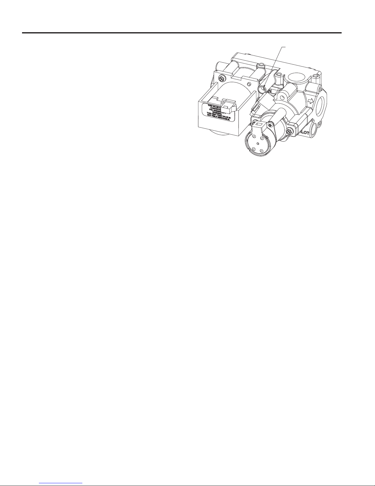
CHECK GAS PRESSURE
Figure 8
Check the gas pressure with the appliance burning and
the control set to HIGH.
Open control access door at bottom front of unit to fi nd
valve and regulator referred to below.
The valve regulator controls the burner pressure which
should be checked at the pressure test point.
Turn captured screw counterclockwise two or three turns
and then place tubing to pressure gauge over test point.
Use test point “A” closest to gas inlet. After taking pressure
reading, be sure and turn captured screw clockwise fi rmly
to reseal. Do not over torque. Check for gas leaks.
Test Port 'A'
FP3036
Figure 8 –
Pressure Test Point Location – Signature Command® Valve
12
20305467
 Loading...