

Vermont Castings 400DVB(N/P)(V/SC)7SB, 300DVBPV7, 500DVB(N/P)(V/SC)7SB, 300DVBNV7, 300DVBNSC7 Installation And Operating Instructions Manual
...
S
For models purchased after 4/16/15, please see addendum.
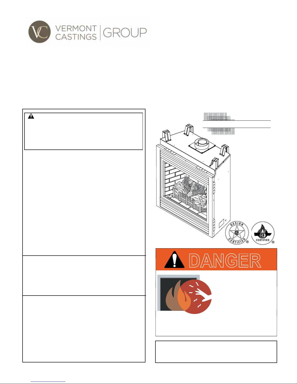
DVB Series Direct Vent Gas Fireplace
Installation and Operating Instructions
Models: 300DVB(N/P)(V/SC)7SB, 400DVB(N/P)(V/SC)7SB,
500DVB(N/P)(V/SC)7SB
WARNING:
FIRE OR EXPLOSION HAZARD
Failure to follow safety warnings exactly
could result in serious injury, death or
property damage.
• Do not store or use gasoline or other
ammable vapors and liquids in the
vicinity of this or any other appliance.
• WHAT TO DO IF YOU SMELL GAS
– Do not try to light any appliance.
– Do not touch any electrical switch; do
not use any phone in your building.
– Leave the building immediately.
– Immediately call your gas supplier from
a neighbor's phone. Follow the gas
supplier's instructions.
– If you cannot reach your gas supplier,
call the re department.
• Installation and service must be performed
by a qualied installer, service agency or
the gas supplier.
WARNING: Improper installation, adjustment,
alteration, service or maintenance can cause
injury or property damage. Refer to this manual.
For assistance or additional information consult
a qualified installer, service agency or the
gas supplier.
This appliance may be installed in an aftermarket,*
permanently located, manufactured home (USA
only) or mobile home, where not prohibited by
local codes.
This appliance is for use only with the type of gas
indicated on the rating plate. This appliance is
not convertible for use with other gases, unless
a certied kit is used.
* Aftermarket: Completion of sale, not for purpose of resale, from
the manufacturer.
CERTIFIED
AFETY BARRIER
DANGER
HOT GLASS WILL
CAUSE BURNS.
DO NOT TOUCH GLASS
UNTIL COOLED.
NEVER ALLOW CHILDREN
TO TOUCH GLASS.
A barrier designed to reduce the risk of burns from
the hot viewing glass is provided with this
appliance and shall be installed.
INSTALLER: Leave this manual with the appliance.
CONSUMER: Retain this manual for future reference.
20306740 11/14 Rev. 1

DVB Series Direct Vent Gas Fireplace
20306740
CONTENTS
Thank you and congratulations on your purchase of a
Vermont Castings Group Fireplace.
PLEASE READ THE INSTALLATION AND OPERATION INSTRUCTIONS BEFORE USING THE APPLIANCE!
IMPORTANT: Read all instructions and warnings carefully before starting installation.
Failure to follow these instructions may result in a possible re hazard and will void the warranty.
Important Safety Information ................................... 3
Code Approval ...................................................... 4
Pre-Installation Information ...................................... 5
Product Specications ..........................................5
High Elevations .....................................................5
Gas Pressures ......................................................5
Gas Specications & Orices ................................ 5
Before You Start .................................................... 5
Fireplace & Framing Dimensions .......................... 6
Firebox Framing .................................................... 7
Fireplace Location ................................................. 7
Cold Climate Insulation ......................................... 7
Clearance to Combustibles ................................... 8
Mantel Clearances ................................................ 8
Secure Fireplace to Floor or Framing ................... 9
Finishing Material .................................................. 9
Venting Installation ..................................................10
Optional Top Vent Application .............................10
Installation Precautions ....................................... 11
General Venting .................................................. 11
Termination Location ........................................... 12
General Information Assembly Vent Pipes .......... 13
Twist Lock Pipes .................................................14
How to Use the Vent Graph ................................ 14
Venting Clearances ............................................. 15
Rear Wall Vent Applications & Installation .......... 16
Top Vent Sidewall Applications & Installation ...... 17
Vertical Sidewall Installation ................................ 19
Below Grade Installations ...................................21
Vertical Through-the-Roof Applications &
Installation ........................................................... 21
Fireplace Installation ............................................... 24
Check Gas Type..................................................24
Installing Gas Piping ........................................... 25
Installation - Millivolt .............................................. 26
Millivolt Check Gas Pressure ..............................26
Electrical Wiring .................................................. 27
Remote Wall Switch Installation ......................... 27
Optional Fan/Blower Systems ............................ 27
Operating Instructions - Millivolt ........................... 28
Lighting Pilot for the First Time ...........................28
Lighting Pilot ....................................................... 29
Lighting Burner .................................................... 30
To Turn Off Gas ................................................... 30
Installation - Signature Command System ........... 31
Check Gas Pressure ........................................... 31
Electrical Installation ........................................... 31
Junction Box Wiring ............................................ 32
Command Center Wall Installation ......................32
Wall Switch Installation ....................................... 32
Signature Command Wiring Diagram .................33
Optional Fan/Blower Systems ............................. 34
Operating Instructions - Signature Command ..... 36
Operating Instructions ......................................... 37
To Turn Off Gas To Appliance .............................37
Features .............................................................. 38
Battery Installation .............................................. 38
System Conguration/Setup ............................... 39
Cold Climate Option ............................................ 39
Functions/Operation ............................................ 40
Final Installation ...................................................... 41
Glass Removal .................................................... 41
Rockwool Placement .......................................... 42
Log Placement .................................................... 42
Lava Rock and Embers Placement ..................... 42
Safety Screen Barrier Installation ....................... 43
Cleaning and Maintenance ..................................... 44
Burner, Pilot and Control Compartment ..............44
Pilot Flame .......................................................... 44
Burner Flame ...................................................... 44
Vent System ........................................................45
Glass Door .......................................................... 45
Logs ....................................................................45
Rock Wool .......................................................... 45
Troubleshooting ......................................................46
Standing Pilot Ignition .........................................46
Signature Command System ..............................47
Replacement Parts .................................................. 48
Firebox Components ........................................... 48
Logs ....................................................................50
Standing Pilot Millivolt Control ........................... 51
Signature Command System ..............................53
Vertical Venting Components .............................. 55
Horizontal Venting Components ......................... 56
Massachusetts Residents Only.............................. 58
Warranty ...................................................................59
Efciencies...............................................................60
2
DVB Series Direct Vent Gas Fireplace
20306740
IMPORTANT SAFETY INFORMATION
INSTALLER
Please leave these instructions with the appliance.
• Read this owner’s manual carefully and completely before trying to assemble, operate, or service
this replace.
• Any change to this replace or its controls can be dangerous.
• Improper installation or use of this replace can cause serious injury or death from re, burns,
WARNING
This replace is a vented product. This replace must be
properly installed by a qualied service person. The glass
door must be properly seated and sealed. If this unit is not
properly installed by a qualied service person with glass
door properly seated and sealed, combustion leakage
can occur.
CARBON MONOXIDE POISONING: Early signs of carbon
monoxide poisoning are similar to the u with headaches,
dizziness and/or nausea. If you have these signs, the re-
place may not have been installed properly. Get fresh air
at once! Have the replace inspected and serviced by a
qualied service person. Some people are more affected
by carbon monoxide than others. These include pregnant
women, people with heart or lung disease or anemia, those
under the inuence of alcohol, and those at high altitudes.
Propane/LP gas and natural gas are both odorless. An
odor-making agent is added to each of these gases. The
odor helps you detect a gas leak. However, the odor added
to these gases can fade. Gas may be present even though
no odor exists.
Make certain you read and understand all warnings. Keep
this manual for reference. It is your guide to safe and proper
operation of this replace.
1. This appliance is only for use with the type of gas
indicated on the rating plate. This appliance is not
convertible for use with other gases unless a certied
kit is used.
2. For propane/LP replace, do not place propane/LP
supply tank(s) inside any structure. Locate propane/
LP supply tank(s) outdoors. To prevent performance
problems, do not use propane/LP fuel tank of less than
100 lbs. capacity.
3. If you smell gas
explosions, electrical shock and carbon monoxide poisoning.
• shut off gas supply.
• do not try to light any appliance.
• do not touch any electrical switch; do not use any
phone in your building.
• immediately call your gas supplier from a neighbor’s
phone. Follow the gas supplier’s instructions.
OWNER
Please retain these instructions for future reference
4. Never install the replace
.
• in a recreational vehicle
• where curtains, furniture, clothing, or other am-
mable objects are less than 42" from the front, top,
or sides of the replace
• in high trafc areas
• in windy or drafty areas
5. This replace reaches high temperatures. Keep children
and adults away from hot surfaces to avoid burns or
clothing ignition. Fireplace will remain hot for a time
after shutdown. Allow surfaces to cool before touching.
6. Young children should be carefully supervised when
they are in the same room as the appliance. Toddlers,
young children and others may be susceptible to
accidental contact burns. A physical barrier is recommended if there are at risk individuals in the house. To
restrict access to a replace or stove, install an adjustable safety gate to keep toddlers, young children and
other at risk individuals out of the room and away from
hot surfaces.
7. Do not modify replace under any circumstances. Any
parts removed for servicing must be replaced prior to
operating replace.
8. Turn replace off and let cool before servicing, installing,
or repairing. Only a qualied service person should
install, service, or repair the replace. Have burner
system inspected annually by a qualied service person.
9. You must keep control compartments, burners, and
circulating air passages clean. More frequent cleaning
may be needed due to excessive lint and dust. Turn off
the gas valve and pilot light before cleaning replace.
10. Have venting system inspected annually by a qualied
service person. If needed, have venting system cleaned
or repaired. Refer to Cleaning and Maintenance, Page 43.
11. Keep the area around your replace clear of combustible materials, gasoline, and other ammable vapor
and liquids. Do not run replace where these are used
or stored. Do not place items such as clothing or dec-
orations on or around replace.
3
DVB Series Direct Vent Gas Fireplace
20306740
12. Do not use this replace to cook food or burn paper or
other objects.
13. Never place anything on top of replace.
14. Do not use any solid fuels (wood, coal, paper, card-
board, etc.) in this replace. Use only the gas type
indicated on rating plate.
15. This appliance, when installed, must be electrically
grounded in accordance with local codes or in the
absence of local codes, with the National Electrical
Code, ANSI/NFPA 70, or the Canadian Electrical Code,
CSA C22.1.
16. Do not obstruct the ow of combustion and ventilation
air in any way. Provide adequate clearances around
air openings into the combustion chamber along with
adequate accessibility clearance for servicing and
proper operation.
17. When the appliance is installed directly on carpeting,
tile or other combustible material other than wood
ooring, you must set appliance on a metal or wood
panel or hearth pad extending the full width and depth
of the appliance.
18. Do not use replace if any part has been exposed to
or has been under water. Immediately call a qualied
service technician to inspect the appliance and replace
any part of the control system and any gas control
which as been submerged in water.
19. Do not operate replace if any log is broken.
20. Do not use a blower insert, heat exchanger insert, or
any other accessory not approved for use with this
replace.
21. Do not operate the replace with glass door removed,
cracked, or broken.
IMPORTANT SAFETY INFORMATION
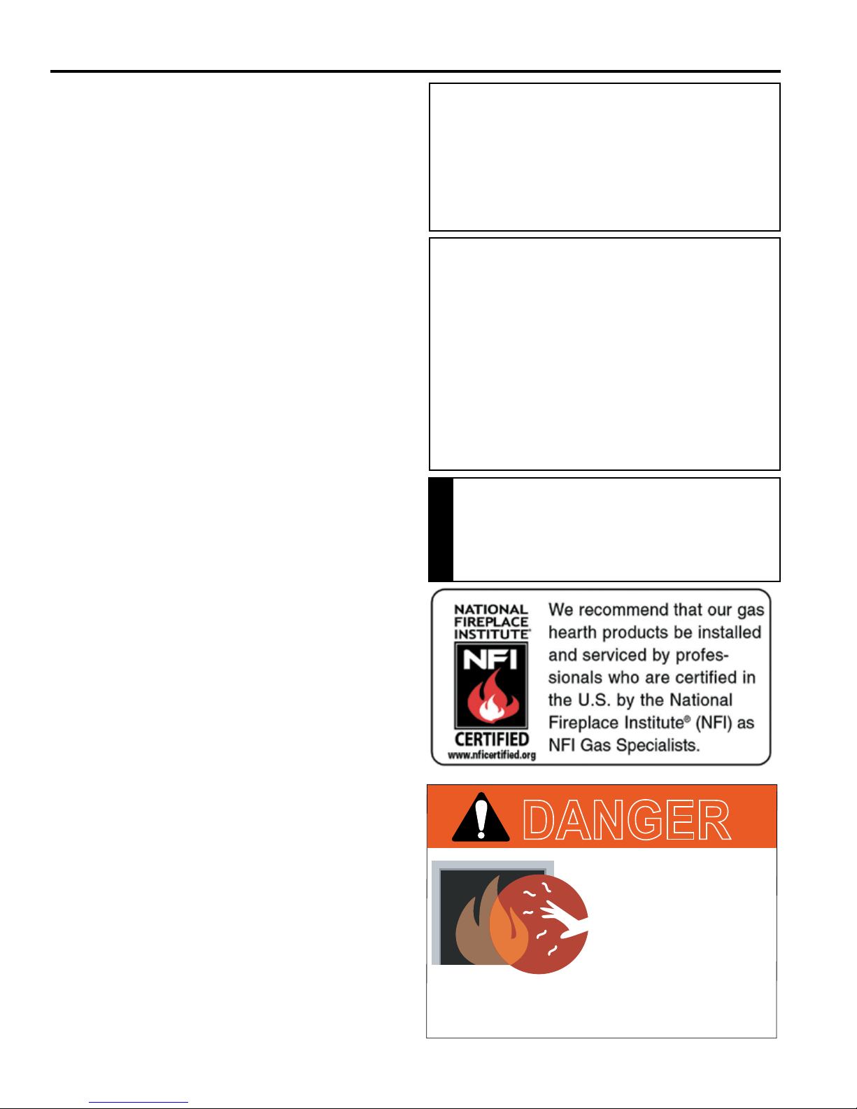
IMPORTANT:
PLEASE READ THE FOLLOWING
CAREFULLY
It is normal for replaces fabricated of steel to give off
some expansion and/or contraction noises during the
start up or cool down cycle. Similar noises are found
with your furnace heat exchanger or car engine.
IMPORTANT:
PLEASE READ THE FOLLOWING
CAREFULLY
It is not unusual for gas replaces to give off some
odor the rst time it is burned. This is due to the
manufacturing process.
Please ensure that your room is well ventilated
during burn off — open all windows.
It is recommended that you burn your replace for at
least ten (10) hours the rst time you use it. Place the
fan switch in the “OFF” position during this time.
Never connect unit to private (non-utility)
gas wells. This gas is commonly known
as wellhead gas.
WARNING
CODE APPROVAL
Direct Vent type appliances draw all combustion air from
outside of the dwelling through the vent pipe.
These appliances have been tested by CSA and found to
comply with the established standards for DIRECT VENT
GAS FIREPLACE HEATERS in the USA and Canada as
follows:
LISTED VENTED GAS FIREPLACE HEATER
TESTED TO:
ANSI Z21.88-2014_CSA 2.33-2014 STANDARDS
A manufactured home (USA only) or mobile home OEM
installation must conform with the Manufactured Home
Construction and Safety Standard, Title 24 CFR, Part
3280, or when such a standard is not applicable, the
Standard for Manufactured Home Installations, ANSI/
NCSBCS A225.1, or Standard for Gas Equipped Rec-
reational Vehicles and Mobile Housing, CSA Z240.4.
4
DANGER
HOT GLASS WILL
CAUSE BURNS.
DO NOT TOUCH GLASS
UNTIL COOLED.
NEVER ALLOW CHILDREN
TO TOUCH GLASS.
A barrier designed to reduce the risk of burns from
the hot viewing glass is provided with this
appliance and shall be installed.
DVB Series Direct Vent Gas Fireplace
20306740
PRE-INSTALLATION INFORMATION
PRODUCT SPECIFICATIONS
This appliance has been certied for use with either
•
natural or propane gas. Refer to appropriate data
plates.
• This appliance is not for use with solid fuels.
• The appliance is approved for bedroom or bedsitting
room installations.
• The appliance must be installed in accordance with local
codes if any. If none exist use the current installation
code. ANSI Z223.1/NFPA 54 in the USA, CSA B149 in
Canada.
• This appliance is mobile home approved.
• The appliance must be properly connected to a venting
system.
• The appliance is not approved for closet or recessed
installations.
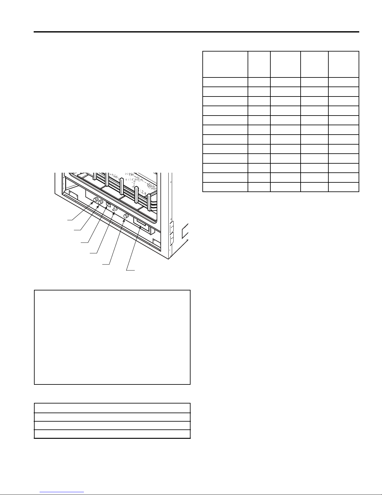
Hi/Lo Knob
Off/Pilot/On Knob
On/Off/RS Switch
Ignitor
Figure 1 -
300/400/500 DVB Fireplace
(Millivolt Control Shown)
Blower Control
Optional Remote
Receiver
FP2087
HIGH ELEVATIONS
Input ratings are shown in BTU per hour and are certied
without deration for elevations up to 4,500 feet (1,370
m) above sea level.
For elevations above 4,500 feet (1,370 m) in USA,
installation must be in accordance with the current
ANSI Z223.1/NFPA 54 and/or local codes having jurisdiction.
In Canada, please consult provincial and/or local authorities having jurisdiction for installation at elevations
above 4,500 feet (1,370 m).
GAS PRESSURES
Natural Propane (LP)
Inlet Minimum 4.5” w.c. 11.0” w.c.
Inlet Maximum 10.5” w.c. 13.0” w.c.
Manifold Pressure 3.5” w.c. 10.0” w.c.
GAS SPECIFICATIONS & ORIFICE SIZE
Max.
Model Fuel
300DVBNV7 Nat. 21,000 15,000 #43
300DVBPV7 LP 21,000 15,000 #54
300DVBNSC7 Nat. 21,000 15,000 #43
300DVBNPC7 LP 21,000 15,000 #54
400DVBNV7 Nat. 24,000 17,000 #41
400DVBPV7 LP 24,000 17,000 #53
400DVBNSC7 Nat. 24,000 17,000 #41
400DVBNPC7 LP 24,000 17,000 #53
500DVBNV7 Nat. 26,000 20,000 #40
500DVBPV7 LP 26,000 20,000 1.55 mm
500DVBNSC7 Nat. 26,000 20,000 #40
500DVBPSC7 LP 26,000 20,000 1.55 mm
Input
BTU/h
Min.
Input
BTU/h
Orice
Size
BEFORE YOU START
Read this homeowner manual thoroughly and follow all
instructions carefully. Inspect all contents for shipping
damage and immediately inform your dealer if any damage
is found. Do not install any unit with damaged, incomplete,
or substitute parts. Check your packing list to verify that
all listed parts have been received. You should have the
following:
• Fireplace (Firebox and Burner System)
• Rock Wool
• Log Set
ITEMS REQUIRED FOR INSTALLATION
• Phillips Screwdriver • Framing Materials
• Hammer • Wall Finishing Materials
• Saw and/or saber saw • Level
• Electric Drill and Bits • Tee Joint
• Pliers • Measuring Tape
• Square • Pipe Wrench
• Caulking Material (Noncombustible)
• Fireplace Surround Material (Noncombustible)
• Piping Complying with Local Codes
• Pipe Sealant Approved for use with Propane/LPG
(Resistant to Sulfur Compounds)
5

DVB Series Direct Vent Gas Fireplace
20306740
FIREPLACE AND FRAMING DIMENSIONS
PRE-INSTALLATION INFORMATION
S
T
S
R
Figure 2 Fireplace and Framing Dimensions
Min. Rough
Opening
Depth
H
Q
Min. Rough
Opening
Height
P
E
D
1/2”
5/8”
O - Min. Rough Opening Width
K
L
C
M
A
1/2”
5/8”
B
N
F
1/2” or 5/8”
G
I
3¹⁄₂”
J
1/2”
5/8"
8¹⁄₄”
300DVB 400DVB 500DVB
A 33
B 29
1
⁄16" (840 mm) 371⁄16" (941 mm) 411⁄16" (1043 mm)
7
⁄8" (759 mm) 32" (813 mm) 36" (914 mm)
C 27" (686 mm) 29" (737 mm) 33" (838 mm)
D 16
1
⁄2" (419 mm) 181⁄2" (470 mm) 201⁄2" (521mm)
E 28" (711 mm) 29" (737 mm) 33" (838 mm)
F 18" (457 mm) 20
G 33
7
⁄8" (860 mm) 371⁄2" (953 mm) 371⁄2" (953 mm)
3
⁄8" (518 mm) 203⁄8" (518 mm)
H 14" (357 mm) 16" (406 mm) 16" (406 mm)
I 37
J 29
K 2
L 1
M 1
N 31
O 33
P 38" (966 mm) 41
Q 13
R 55
S 39
T 271
7
⁄8" (962 mm) 411⁄2" (1054 mm) 411⁄2" (1054 mm)
5
⁄8" (753 mm) 331⁄8" (841 mm) 331⁄8" (841 mm)
1
⁄8" (54 mm) 11⁄4" (32 mm) 11⁄4" (32 mm)
1
⁄2" (38 mm) 21⁄2" (64 mm) 21⁄2" (64 mm)
5
⁄16" (24 mm) 15⁄16" (24 mm) 15⁄16" (24 mm)
5
⁄8" (803 mm) 343⁄4" (883 mm) 343⁄4" (883 mm)
1
⁄2" (851 mm) 371⁄2" (953 mm) 411⁄2" (1054 mm)
5
⁄8" (1057 mm) 415⁄8" (1057 mm)
3
⁄4" (349 mm) 153⁄4" (400 mm) 153⁄4" (400 mm)
1
⁄16" (1414 mm) 607⁄8" (1546 mm) 647⁄8" (1648 mm)
3
⁄8" (1000 mm) 431⁄16" (1094 mm) 457⁄8" (1165 mm)
3
⁄16" (706 mm) 307⁄16" (773 mm) 327⁄16" (824 mm)
6
DVB Series Direct Vent Gas Fireplace
20306740
PRE-INSTALLATION INFORMATION
FIREBOX FRAMING
Firebox framing can be built before or after the appliance
is set in place. Refer to Figure 2 for replace and framing
dimensions. Construct rebox framing following Figure 2
for your specic installation requirements. The framing
headers may rest on the top of the rebox standoffs. Do
not bring headers below top of standoffs.
The rebox may be installed directly on a combustible oor
or raised on a platform of an appropriate height. When
the rebox is installed directly on carpeting, tile, or other
combustible material, other than wood ooring, the rebox
shall be installed on a metal or wood panel extending the
full width and depth of the enclosure.
FIREPLACE LOCATION
Plan for the installation of your appliance. This includes
determining where the unit is to be installed, the vent con-
guration to be used, framing and nishing details, and
whether any optional accessories (i.e. blower, wall switch,
or remote control) are desired. Consult your local building
code agency to ensure compliance with local codes, including permits and inspections.
The following factors should be taken into consideration:
• Clearance to side-wall, ceiling, woodwork, and win-
dows. Minimum clearances to combustibles must be
maintained.
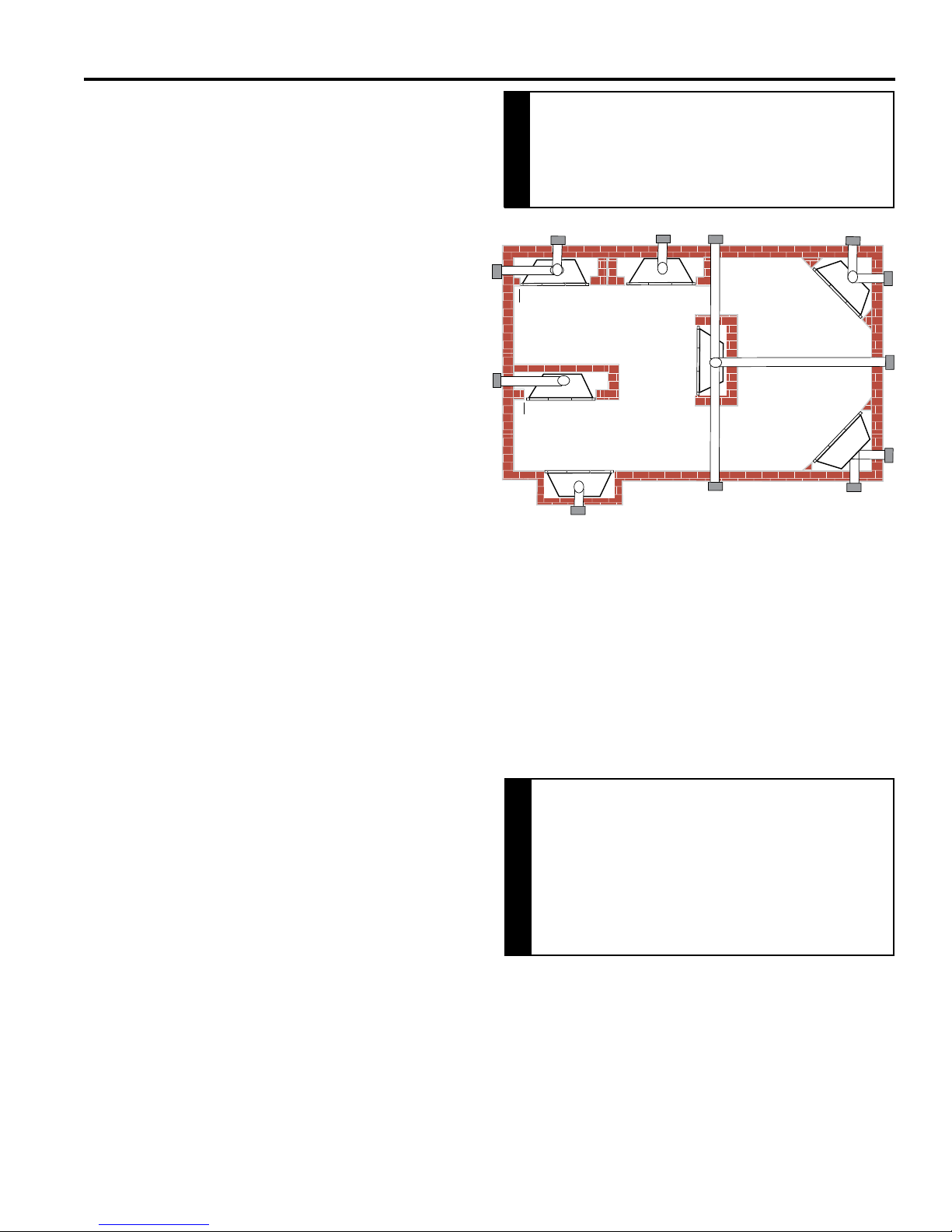
• This replace may be installed along a wall, across a
corner, or use an exterior chase. Refer to Figure 3 for
suggested locations.
• Location should be out of high trafc areas and away
from furniture and draperies due to heat from appliance.
• Never obstruct the front opening of the replace.
• Do not install in the vicinity where gasoline or other
ammable liquids may be stored.
• Vent pipe routing. Refer to Venting section found in
this manual for allowable venting congurations.
• These units can be installed in a bedroom. See Na-
tional Fuel Gas Code ANSI Z233.1/NFPA 54 — (current edition), the Uniform Mechanical Code — (current
edition), and Local Building Codes for specic installation requirements.
Do not ll spaces around rebox with
insulation or other materials. This could
cause a re.
WARNING
E
Y
D
Y
F
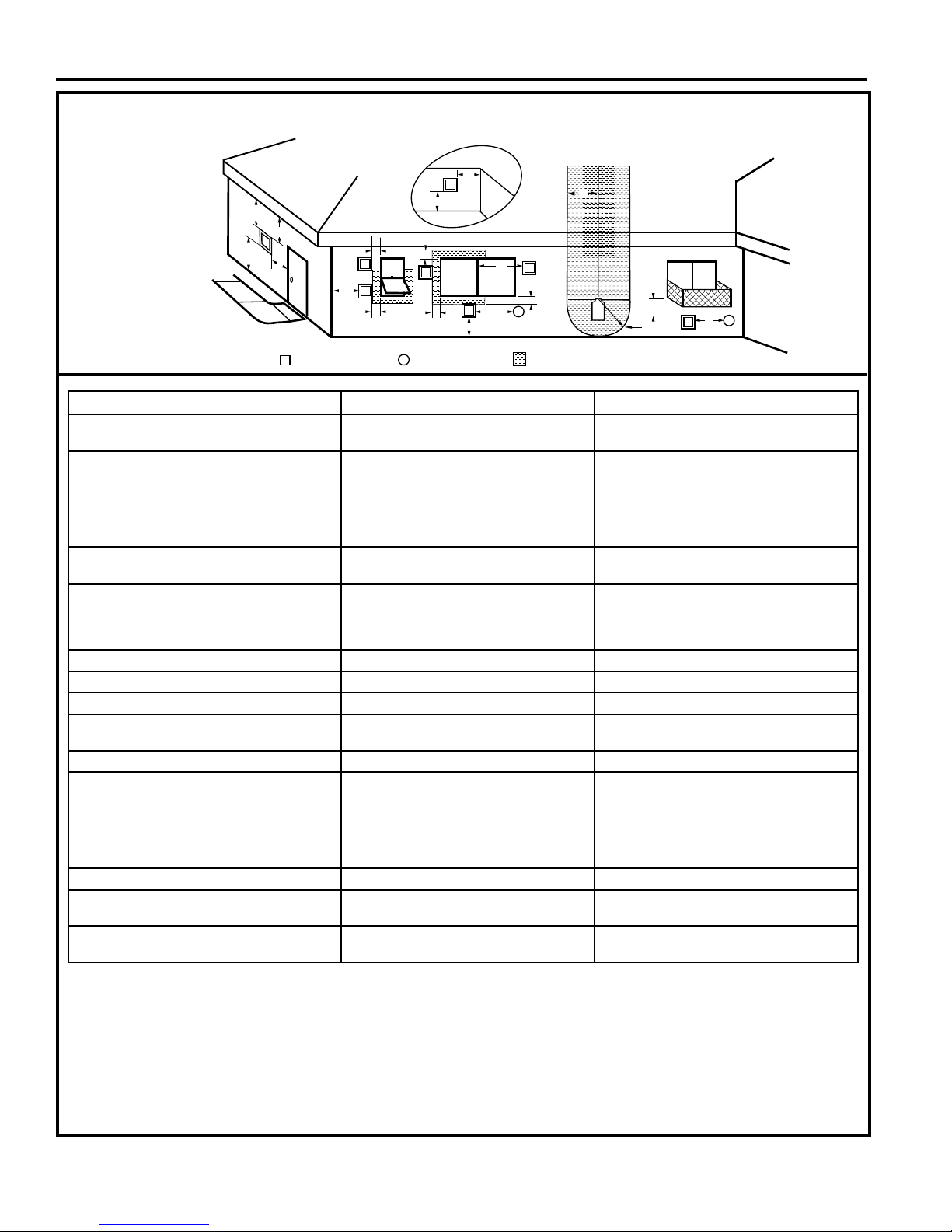
Figure 3 Fireplace Locations
** Island (C) and room divider (D) installation is possible as long
as the horizontal portion of vent system (X) does not exceed
20'. Refer to Termination Location on Pages 12 and 13.
* When you install your replace in (D) room divider or (E)
at on wall corner positions (Y), a minimum of 6" clearance
must be maintained from perpendicular wall and front of
replace.
A
C
A Flat on Wall
B Cross Corner
C Island**
D Room Divider*
E Flat on Wall Corner*
F Chase Installation
Y 4” Minimum
B
X
B
COLD CLIMATE INSULATION
If you live in a cold climate, seal all cracks
around your appliance, and wherever cold air
could enter the room, with noncombustible
material. It is especially important to insulate
NOTE
the outside chase cavity between the studs
and under the oor on which the appliance
rests, if the oor is above ground level.
NOTE: Refer to cold climate pilot information on Page 39
for more information on standing pilot vs. intermittent pilot
options.
7
DVB Series Direct Vent Gas Fireplace
20306740
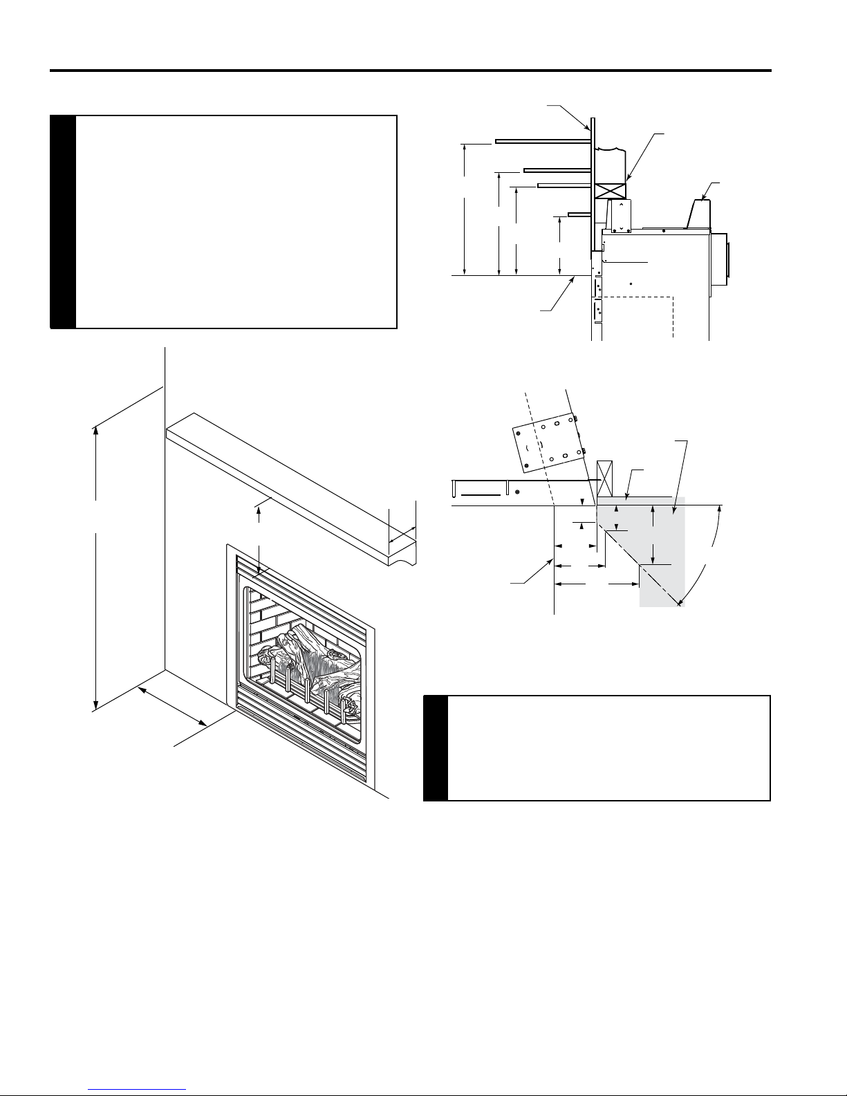
CLEARANCES TO COMBUSTIBLES
PRE-INSTALLATION INFORMATION
Wall
Follow these instructions carefully to
ensure safe installation. Failure to follow
instructions exactly can create a fire
hazard.
The appliance cannot be installed on a carpet,
tile or other combustible material other than
wood ooring. If installed on carpet or vinyl
WARNING
ooring, the appliance shall be installed on
a metal, wood or noncombustible material
panel extending full width and depth of the
appliance.
Ceiling
Combustible Mantel
71” Minimum
11” Minimum
12”
Max.
11”
7”
Top of Exhaust
Louvers
FP2093a
Side of Fireplace Opening
12”
8”
5”
6”
2”
3”
Side View
1"
2¹⁄₂”
3"
Stud
Standoff
FP2204
Combustible
Material Area
Wall
1¹⁄₂”
2¹⁄₂”
45°
4"
Min. 4”
From Either
Side Wall
Figure 4 Clearances
MANTEL CLEARANCES
NOTE: The combustible area above the facing must
not protrude more than 1/2" from the facing. If it does,
it is considered a mantel and must meet the mantel
requirements listed in this manual.
NOTE: The Vermont Castings Group Barrington Cabinet
Mantel Model series BWC300, BWC400 and BWC500
are specially designed to comply with all mantel temperature requirements. Any custom-built mantel must comply
with all clearance requirements shown in this instruction
manual.
Top View
Figure 5 Mantel Clearances
Never obstruct or modify the air inlet or
outlet grilles (louvers). This may create
a re hazard.
WARNING
8
DVB Series Direct Vent Gas Fireplace
20306740
PRE-INSTALLATION INFORMATION
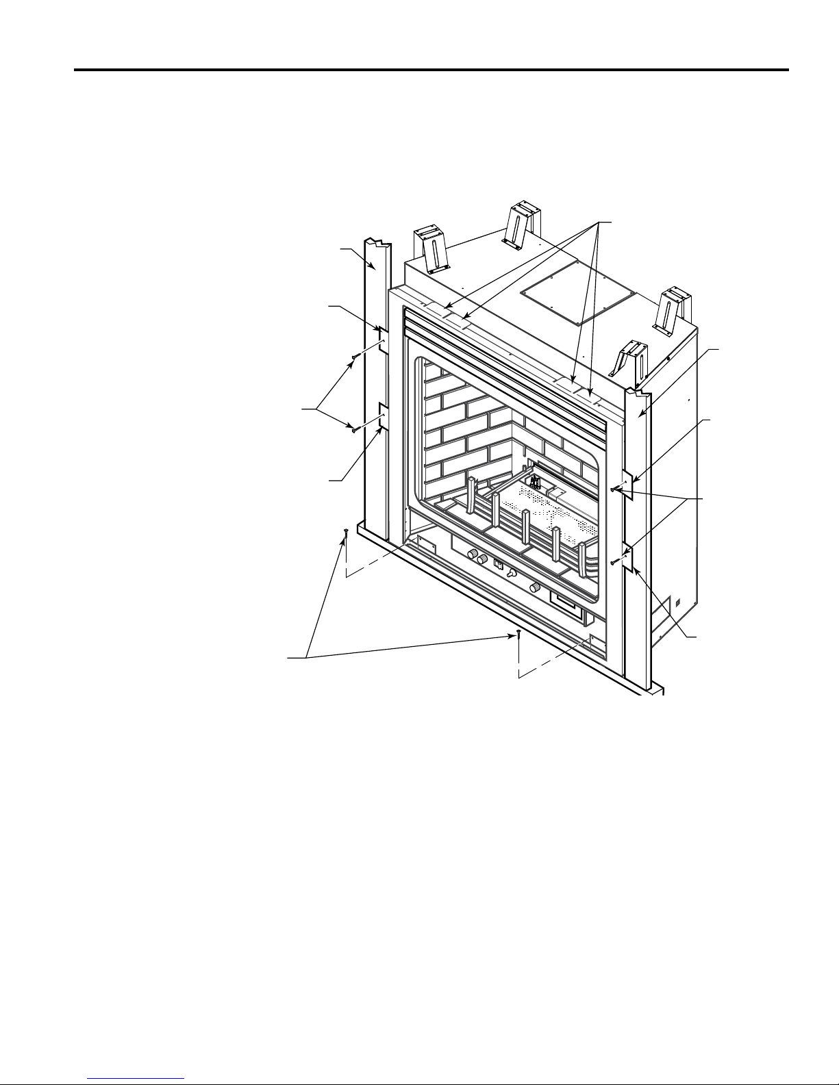
SECURE FIREPLACE TO FLOOR or FRAMING
The replace must be secured to the oor and/or to framing
studs as shown in Figure 6. Use two (2) wood screws or
masonry/ concrete screws to secure replace to the oor.
Use four (4) screws to attach replace to framing. The side
nailing anges are 1/2" or 5/8" to accommodate different
wall thickness.
Framing
Nailing Flange
Drywall Support Tabs
(Do not use for framing or
header)
Framing
Screws
Nailing Flange
Screws
Figure 6 Secure Fireplace to Floor and Framing Studs
FINISHING MATERIAL
NOTE: Any remote wiring (i.e. remote control, wall switch,
and optional fan) must be done prior to nal nishing to
avoid costly reconstruction.
Only noncombustible materials (i.e. brick, tile, slate, steel,
or other materials with a UL re rating of Zero) may be
used to cover the black surface of the appliance. A 300°F
minimum adhesive may be used to attach facing materials
to the black surface. If joints between the nished wall
and the replace surround are sealed, a 300°F minimum
sealant material (General Electric RTV103 or equivalent)
must be used.
Nailing Flange
Screws
Nailing Flange
FP2094a
9
DVB Series Direct Vent Gas Fireplace
20306740
For models purchased after 4/16/15, please see addendum.
VENTING INSTALLATION
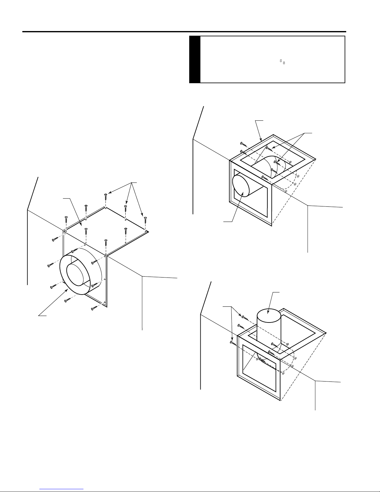
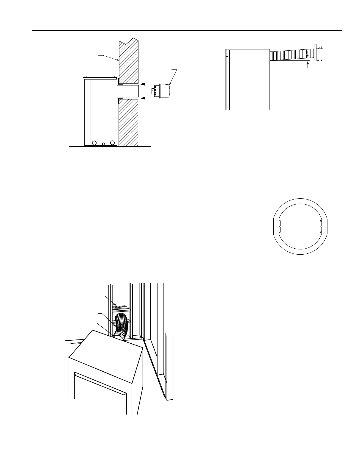
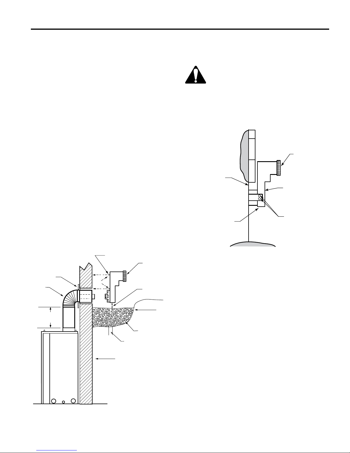
OPTIONAL TOP VENT APPLICATION
The appliance is shipped as a rear vent unit. If the installa-
tion layout requires the unit to be a top vent conguration
the appliance can be converted by following the steps
below.
When removing and retting the plates and adapter be
sure the associated gaskets are undamaged and retted
as required.
1. Remove the eight (8) screws securing the ue pipe
adapter to the replace body. Figure 7
2. Set the ue pipe adapter aside, complete with the
gasket. Do not damage the gaskets as the adapter and
gasket must be retted.
3. Remove the eight (8) screws securing the ue pipe
cover to the top of the intake box and remove the cover
and gasket. Figure 7
Screws
Flue Pipe
Cover
After conversion to top vent conguration,
the 4” (102 mm) flue pipe should be
concentric within the 65⁄8” (175 mm) outer
collar (within 1/4”)
WARNING
Flue Cover
Screws
Flue Pipe
Adapter
Figure 7 Remove 16 Screws from Flue Pipe Adapter and Flue
Pipe Cover
FP1991
4. Remove six (6) screws securing the ue pipe to the
back of the intake box and remove the pipe and gasket.
Figure 8
5. Replace ue pipe to top of rebox. Ensure the gasket
is in place and undamaged. Secure with six (6) screws.
Figure 9
6. Place the ue pipe cover and gasket removed in step
3 over the ue opening in back of the intake box.
7. Ret the ue pipe adapter and gasket to the top of
replace. Secure the adapter with eight (8) screws re-
moved in Step 1.
Flue Pipe
FP1992
Figure 8 Remove Flue Pipe
Flue Pipe
Screws
FP1993
Figure 9 Attach Flue Pipe to Top Vent Configuration
10

DVB Series Direct Vent Gas Fireplace
20306740
For models purchased after 4/16/15, please see addendum.
VENTING INSTALLATION
Read all instructions completely and
thoroughly before attempting installation.
Failure to do so could result in serious
injury, property damage or loss of life.
Operation of improperly installed and
maintained venting system could result in
WARNING
serious injury, property damage or loss of
life.
INSTALLATION PRECAUTIONS
Consult local building codes before beginning the
installation. The installer must make sure to select the
proper vent system for installation. Before installing vent
kit, the installer must read this replace manual and vent
kit instructions.
Only a qualied installer/service person should install venting system. The installer must follow these safety rules:
• Wear gloves and safety glasses for protection.
• Use extreme caution when using ladders or when on
rooftops.
• Be aware of electrical wiring locations in walls and
ceilings.
The following actions will void the warranty on your venting system:
• Installation of any damaged venting component.
• Unauthorized modication of the venting system.
• Installation of any component part not manufactured
or approved by MHS.
• Installation other than permitted by these instruc-
tions.
Always maintain minimum clearances around
vent systems. The minimum clearances to
combustibles for horizontal vent pipe are 3"
at the top* and 1" at the sides and bottom
of the vent system until the pipe penetrates
the nearest vertical wall (1" required). A 1"
minimum clearance all around the pipe must
be maintained at outside wall and on vertical
runs. Do not pack the open air spaces with
WARNING
insulation or other materials. This could
cause high temperatures and may present
a re hazard.
* Unless the vertical run is 71/2 feet or higher
(top vent units only), the clearances for the
horizontal run is 1" at the top.
GENERAL VENTING
Your replace is approved to be vented either through the
side wall, or vertical through the roof.
• Only Vermont Castings Group venting compo-
nents specically approved and labelled for this
replace may be used.
• Flexible UL1777 listed venting may be used in any
venting application where rigid direct vent components
can be used. All restrictions, clearances and allowanc-
es that pertain to the rigid piping apply to the exible
venting.
Flex kits may not be modied. Flex kits may be added
to the end of a vent run made of rigid vent sections
using pipe manufacturer's approved ex to pipe adapters. This may occur only if doing so does not violate
any of the venting length, height, routing, horizontal to
vertical raito requirements or clearance considerations
detailed in this manual.
• Venting terminals shall not be recessed into a wall or
siding.
• Horizontal venting which incorporates the twist lock
pipe must be installed on a level plane without an inclining or declining slope.
• Horizontal venting which incorporates the use of ex
venting shall have an inclining slope from the unit of 1”
(25 mm) per 24” (610 mm).
There must not be any obstruction such as bushes, garden sheds, fences, decks or utility buildings within 24”
(610 mm) from the front of the termination hood.
Do not locate termination hood where excessive snow or
ice build up may occur. Be sure to check vent termination area after snow falls, and clear to prevent accidental
blockage of venting system. When using snow blowers,
make sure snow is not directed towards vent termination
area.
Location of Vent Termination
It is imperative the vent termination be located observing
the minimum clearances as shown on following page.
This fireplace must be vented to the
outside. The venting system must NEVER
be attached to a chimney serving a separate
solid fuel burning appliance. Each gas
appliance must use a separate vent system.
WARNING
Do not use common vent systems.
Failure to follow these instructions will
void the warranty.
NOTICE
11
DVB Series Direct Vent Gas Fireplace
20306740
V
X
X
X
D
E
B
B
B
C
B
M
B
A
J
K
F
L
VENT TERMINATION AIR SUPPLY INLET
AREA WHERE TERMINAL IS NOT PERMITTED
H
I
Fixed
Closed
Operable
Operable
Fixed
Closed
B
INSIDE
CORNER DETAIL
A
G
CFM145a
V
V
V
V
V
V
V
V
For models purchased after 4/16/15, please see addendum.
TERMINATION LOCATION
Figure 15 –
Termination Locations
VENTING INSTALLATION
A = Clearance above grade, veranda, porch,
CANADIAN INSTALLATIONS
1
12" (30cm) 12" (30cm)
US INSTALLATIONS
2
deck or balcony
B = Clearance to window or door that may be
opened
C = Clearance to permanently closed window 12" (305mm) recommended to prevent
D = Vertical clearance to ventilated soft
6" (15cm) for appliances <10,000 BTU/h
(3kW)
12" (30cm) for appliances >10,000 BTU/h
(3kW) and <100,000 BTU/h (30kW)
36" (91cm) for appliances >100,000 BTU/h
(30kW)
6" (15cm) for appliances <10,000 BTU/h
(3kW)
9" (23cm) for appliances >10,000 BTU/h
(3kW) and <50,000 BTU/h (15kW)
12" (30cm) for appliances >50,000 BTU/h
(15kW)
12" (305mm) recommended to prevent
window condensation
window condensation
18" (458mm) 18" (458mm)
located above the terminal within a horizontal distance of 2' (610 mm) from the
center line of the terminal
E = Clearance to unventilated soft 12" (305mm) 12" (305mm)
F = Clearance to outside corner see next page see next page
G = Clearance to inside corner see next page see next page
H = Clearance to each inside of center line
extended above meter/regulator assembly
3' (91cm) within a height of 15' (5m) above
the meter/regulator assembly
3' (91cm) within a height of 15' (5m) above
the meter/regulator assembly
I = Clearance to service regulator vent outlet 3' (91cm) 3' (91cm)
J = Clearance to non-mechanical air supply
inlet to building or the combustion air inlet
to any other appliance
6" (15cm) for appliances <10,000 BTU/h
(3kW)
12" (30cm) for appliances >10,000 BTU/h
(3kW) and <100,000 BTU/h (30kW)
36" (91cm) for appliances >100,000 BTU/h
(30kW)
6" (15cm) for appliances <10,000 BTU/h
(3kW)
9" (23cm) for appliances >10,000 BTU/h
(3kW) and <50,000 BTU/h (15kW)
12" (30cm) for appliances >50,000 BTU/h
(15kW)
K = Clearance to mechanical air supply inlet 6' (1.83m) 3' (91cm) above if within 10' (3m) horizontally
L = Clearance above paved sidewalk or
7' (2.13m)
†
7' (2.13m)
†
paved driveway located on public property
M = Clearance under veranda, porch, deck or
12" (30cm)
‡
12" (30cm)
‡
balcony
1 In accordance with the current CSA-B149 Installation Codes
2 In accordance with the current ANSI Z223.1/NFPA 54 National Fuel
Gas Codes
† A vent shall not terminate directly above a sidewalk or paved
driveway which is located between two single family dwellings and
serves both dwellings
‡ Only permitted if veranda, porch, deck or balcony is fully open on a
minimum 2 sides beneath the oor.
12
NOTE: 1. Local codes or regulations may require different
clearances.
2. The special venting system used on Direct Vent
Fireplaces are certied as part of the appliance, with
clearances tested and approved by the listing agency.
3. Vermont Castings Group assumes no responsibility for
the improper performance of the appliance when the venting
system does not meet these requirements.
DVB Series Direct Vent Gas Fireplace
20306740
For models purchased after 4/16/15, please see addendum.
VENTING INSTALLATION
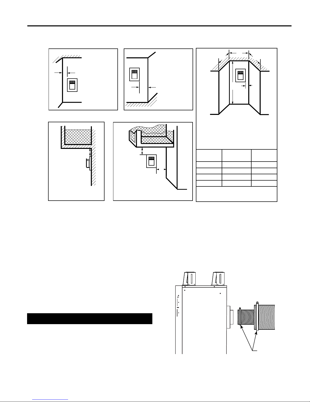
Termination Clearances
Termination clearances for buildings with combustible and noncombustible exteriors.
Inside Corner
Outside Corner
Alcove Applications*
D
G
V
Balcony -
with no side wall
G =
Combustible
6" (152 mm)
Noncombustible
2" (51 mm)
F =
Combustible
6" (152 mm)
V
Noncombustible
2" (51 mm)
F
Balcony -
with perpendicular side wall
C
O
E = Min. 2” (51 mm) for
non-vinyl sidewalls
Min. 12” (305 mm) for
vinyl sidewalls
C
V
E
O = 8’ (2.4 m) Min.
M
V
M =
Combustible &
Noncombustible
12" (305 mm)
*NOTE: Termination in an alcove space (spaces open only on one side and with an overhang) is permitted with the dimensions specied for vinyl or
non-vinyl siding and softs. 1. There must be a 3’ (914 mm) minimum between termination caps. 2. All mechanical air intakes within 10’ (1 m) of a
termination cap must be a minimum of 3’ (914 mm) below the termination cap. 3. All gravity air intakes within 3’ (914 mm) of a termination cap must
be a minimum of 1’ (305 mm) below the termination cap.
Combustible &
Noncombustible
M = 12" (305 mm)
P = 6” (152 mm)
M
V
P
No.
of Caps D
C
Min.
1 3’ (914 mm) 2 x D
2 6’ (1.8 m) 1 x D
3 9’ (2.7 m) 2/3 x D
4 12’ (3.7 m) 1/2 x D
D
= # of Termination caps x 3
Min.
C
= (2 / # termination caps) x D
Max.
Max.
Actual
Actual
Actual
Actual
Actual
584-15
Figure 11 Termination Clearances
GENERAL INFORMATION ASSEMBLING
VENT PIPES
USA Installations
The venting system must conform to local codes and/or
the current National Fuel Code ANSI Z223.1/NFPA 54.
Only venting components manufactured or approved by
Vermont Castings Group may be used in Direct Vent systems.
Canadian Installations
The venting system must be installed in accordance with
the current CSA-B149.1 installation code.
* Be sure the vent is actually crushed before proceeding.
Apply a tug to be sure the vent will not slip off the collars.
Repeat process with 7” ex vent pipe. The same procedure must be performed on the vent side.
Flex Vent Pipes
Secure ex vent pipe in place with a hose clamp (provided).
*Be sure the ex pipe overlaps at least 1” (25 mm) onto
the collars of the replace and termination. If the termi-
nation has an internal bead, be sure to overlap and secure 1” (25 mm) past the bead.
FP2290
Figure 12 Secure Flex Pipewith Hose Clamps
Hose Clamp
13
DVB Series Direct Vent Gas Fireplace
20306740
For models purchased after 4/16/15, please see addendum.
VENTING INSTALLATION
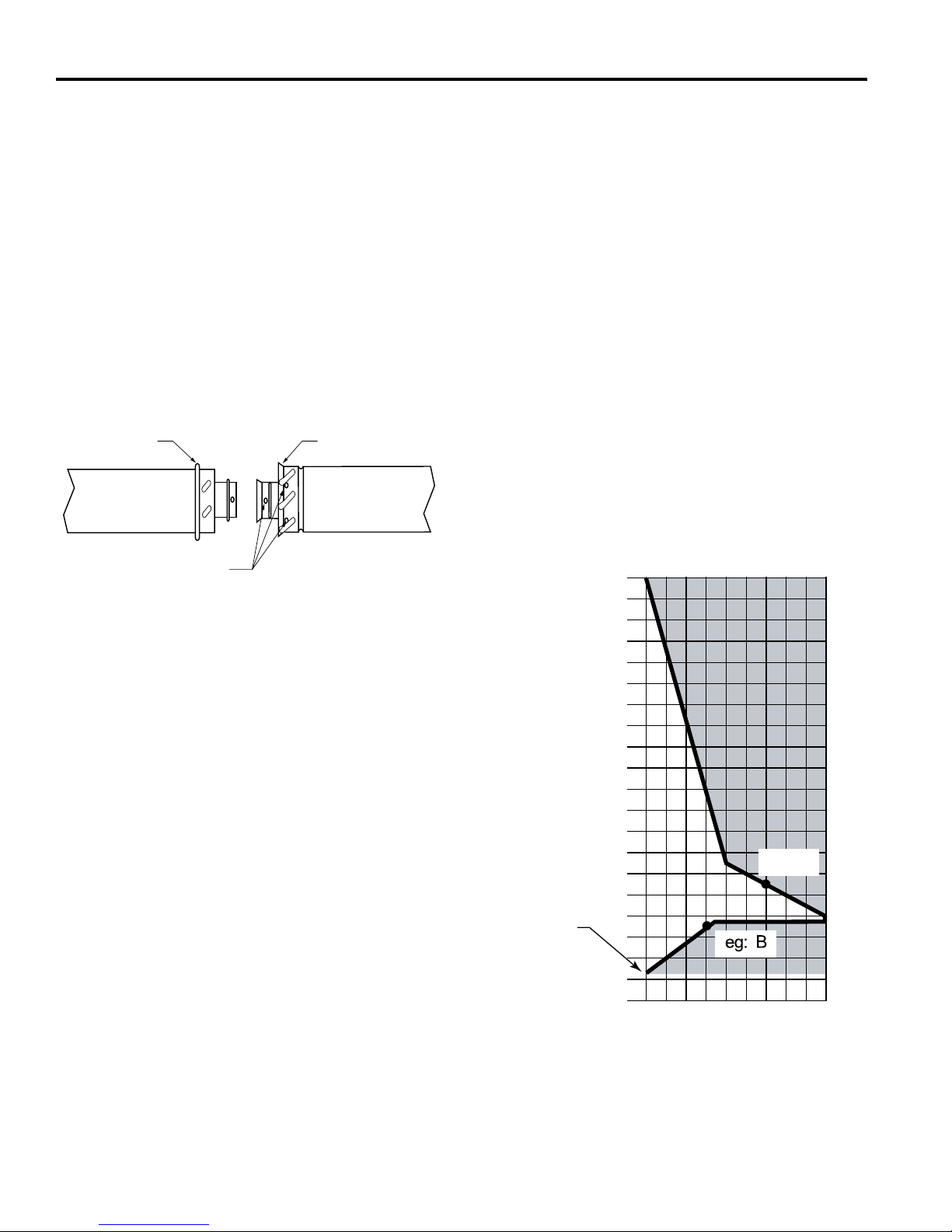
TWIST LOCK PIPES
When using twist lock pipe it is not necessary to use sealant on the joints.
To join twist lock pipes together, simply align the beads of
the male end with the grooves of the female end, twisting
the pipe until the ange on the female end contacts external ange on the male end. It is recommended that you
secure the joints with three (3) sheet metal screws, however, this is not mandatory with twist lock pipe. Figure 13
NOTE: Sealant is not required to assemble replace
venting. Do not use silicone sealant at the inner ue
exhaust connections.
To make it easier to assembly the joints, we suggest putting a lubricant (Vaseline or similar) on the male end of the
twist lock pipe prior to assembly.
Male End
Screw Holes
Figure 13 Twist-lock Pipe Joints
Female End
TWL100
HOW TO USE THE VENT GRAPH
The Vent Graph should be read in conjunction with the
following vent installation instructions to determine the relationship between the vertical and horizontal dimensions
of the vent system.
1. Determine the height of the center of the horizontal
vent pipe exiting through the outer wall. Using this dimension on the Sidewall Vent Graph, Figure 14, locate
the point intersecting with the slanted graph line.
2. From the point of this intersection, draw a vertical line
to the bottom of the graph.
3. Select the indicated dimension, and position the replace in accordance with same.
EXAMPLE A:
If the vertical dimension from the oor of the unit is 11’
(3.4 m) the horizontal run to the face of the outer wall
must not exceed 14’ (4.3 m).
EXAMPLE B:
If the vertical dimension from the oor of the unit is 7’ (2.1
m), the horizontal run to the face of the outer wall must
not exceed 81/2’ (2.6 m).
Refer to Page 21 for requirements for snorkels.
40
38
36
34
32
30
28
26
24
22
20
18
the Horizontal Vent Pipe
Vertical Dimension from the Floor of Unit to the Center of
20”
16
14
12
10
8
6
4
2
eg: A
14
4 6 8 10 12 14 16 18 20
2
Horizontal Dimension From the Outside of Termination to
Figure 14 Side Wall Venting Graph
the Back of the Fireplace

DVB Series Direct Vent Gas Fireplace
20306740
For models purchased after 4/16/15, please see addendum.
VENTING INSTALLATION
Horizontal sections of this vent system
require a minimum of 3” clearances to
combustibles at the top of the ue and 1”
clearance at the sides and bottom until
the flue penetrates the outside wall. A
minimum 1” clearance all around the ue
is acceptable at this point of penetration. If
vertical rise is 71/2 feet or higher when top
venting, the clearance to combustibles is
WARNING
1” on all sides of the horizontal run.
Vertical sections of this vent system require
a minimum of 1” clearance to combustibles
on all sides of the pipe.
*3”
**1”
This fireplace must be vented to the
outside. The venting system must NEVER
be attached to a chimney serving a separate
solid fuel burning appliance. Each gas
appliance must use a separate vent system.
WARNING
Do not use common vent systems.
***44¹⁄₂” (1130 mm)
for 300 Series
Figure 15 Combustible Clearances for Vent Pipe
**1”
48”
(1219 mm)***
*3"
**1"
**1"
33¹⁄₈”
(841 mm)***
***29⁵⁄₈" (753 mm)
for 300 Series
FP2095a
* A Minimum 3” Clearance to the Top is
Required Along Horizontal Length until
Flue Pipe Penetrates Outside Wall
** A Minimum 1” Clearance to Combustibles Permitted All Around Flue at Outside Wall
15
DVB Series Direct Vent Gas Fireplace
20306740
For models purchased after 4/16/15, please see addendum.
VENTING INSTALLATION
REAR WALL VENT APPLICATION
When installed as a rear vent unit this appliance may be
vented directly to a termination located on the rear wall
behind the appliance.
• Only Vermont Castings Group venting components
are approved to be used in these applications (Refer
to ‘Venting Components’ listed for different installation
requirements).
• The maximum horizontal distance between the rear of
the appliance (or end of the transition elbow in a corner application) and the outside face of the rear wall is
20” (508 mm). Figure 15
• Only one 45° elbow is allowed in these installations.
• Minimum clearances between vent pipe and combus-
tible materials are as follows:
Top - 3” (76 mm)
- except at outside wall 1" (25 mm)
Sides - 1” (25 mm)
Bottom - 1” (25 mm)
Rear Vent Top
View
20”
(508 mm)
Max.
Figure 16 Rear Vent Appliaction, No Elbows
20”
(508 mm)
Max.
FP1188
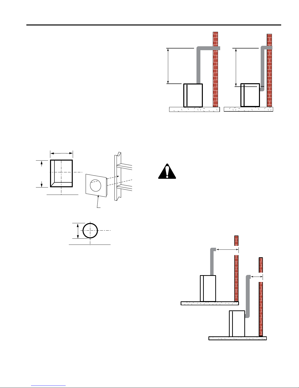
REAR WALL VENT INSTALLATION - TWIST
LOCK PIPE
Step 1
Locate and cut the vent opening in the wall.
For combustible walls rst frame in opening. Figure 17
NOTE: When using ex vent, the opening will have to be
measured according to the 1” (25 mm) rise in 24” (610
mm) vertical run.
Combustible Walls: Cut a 95/8”H x 95/8” W (244 x 244
mm) hole through the exterior wall and frame as shown.
Figure 17
Noncombustible Walls: Hole opening should be 71/2”
(191 mm) diameter.
Vent Opening for Combustible Walls
95/8”
(244 mm) Min.
95/8”
(244 mm)
Min.
Fireplace Hearth
Opening for Noncombustible Wall
71/2”
(190 mm)
Figure 17 -
Locate vent opening on wall.
Fireplace Hearth
Framing Detail
FP2293
Step 3
Measure the horizontal length requirement for the venting
including a 2” (51 mm) overlap, i.e. from the elbow to the
outside wall face plus 2” (51 mm). Figure 16
Step 4
Install the 4” (102 mm) vent to the appliance collar and
secure with 3 sheet metal screws. Install the 7” (178 mm)
vent pipe to the appliance collar and secure with 3 sheet
metal screws. It is not necessary to seal this connection.
If a 45° elbow is being used attach the elbow to the appliance in the same manner then attach the venting to the
elbow.
It is critical that there is no downward slope
away from the appliance when connecting
the vent or elbow.
Step 5
Guide the venting through the vent hole as you place the
appliance in its installed position. Guide the 4” (102 mm)
and 7” (178 mm) collar of the vent termination into the
outer ends of the venting. Do not force the termination. If
the vent pipes do not align with the termination, remove
and realign the venting at the appliance ue collars. Figure 18. Attach the termination to the wall as outlined in the
instruction sheet supplied with the termination.
Step 2
Secure restop to the inside frame, center in the 95/8" x
95/8" vent opening.
16
DVB Series Direct Vent Gas Fireplace
20306740
For models purchased after 4/16/15, please see addendum.
VENTING INSTALLATION
Finish Wall
Vent
Termination
Figure 18 Side View of Final Unit Location
REAR WALL VENT INSTALLATIONS FLEX VENT PIPE
Follow Steps 1 and 2 on Page 16.
Step 3
Install the 4” (102 mm) ex vent pipe to the appliance collars described in “General Information Assembling Vent
Pipes”, Page 13. If the installation requires a 45° angle,
grasp the vent pipe close to the appliance collar and bend
to 45°. DO NOT exceed 45°. Figure 19
Install the 7” vent pipe in the same manner as Step 2.
NOTE: There must be a 1/2” (13 mm) rise in a 12” (305
mm) length of ex vent.
Step 4
Assemble the ex vent to the collars on the termination as
you did on the appliance.
Termination
Flex Section
Appliance Collars
Figure 19 Grasp the vent pipe close to the collar and
bend to 45° angle. do not exceed 45°.
FP2294
FP1473
Rise
FP1472
Figure 20 There must be a 1/2" rise per foot length
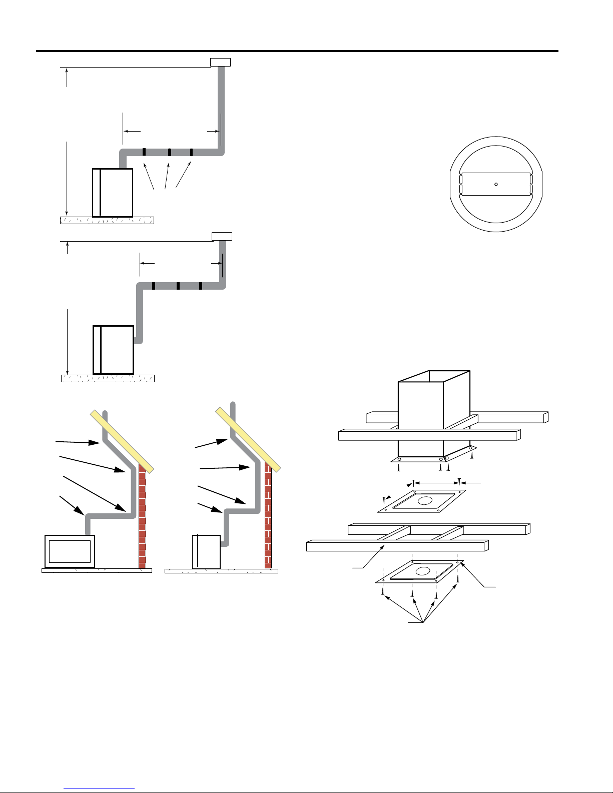
TOP VENT SIDEWALL APPLICATION
NOTE: For all top vent installations where a 90° elbow
is the rst pipe piece towards a sidewall termination (up
and out), an open-center ringed ue restrictor must be
installed onto the top edge of the rebox ue adapter. To
create this open-center restrictor, twist and break off the
center rib of the supplied ue restrictor. The installed part
should appear similar to that show n in Figure 21.
Since it is very important
that the venting system
maintain its balance between the combustion air
intake and the ue gas ex-
haust, certain limitations
as to vent congurations apply and
must be strictly adhered to.
Figure 21 Top Vent Vertical Sidewall
Restrictor
The Vent Graph,
showing the relationship between vertical and horizontal
side wall venting, will help to determine the various dimensions allowable.
Minimum clearance between vent pipes and combustible materials is 3" (76 mm) on top, and 1" (25 mm) on
the bottom and sides unless otherwise noted.
When vent termination exits through foundations less
than 20” (508 mm) below siding outcrop, the vent pipe
must ush up with the siding.
It is best to locate the replace in such a way that mini-
mizes the number of offsets and horizontal vent length.
The horizontal vent run refers to the total length of vent
pipe from the ue collar of the replace (or the top of the
Transition Elbow) to the face of the outer wall.
Horizontal plane means no vertical rise exists on this portion of the vent assembly.
FP2303
17
DVB Series Direct Vent Gas Fireplace
20306740
For models purchased after 4/16/15, please see addendum.
VENTING INSTALLATION
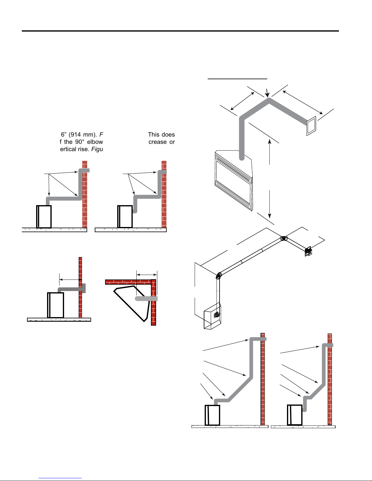
When installing the appliance as a rear vent unit, the
90° or 45° Transition Elbow attached directly to the
rear of the unit is NOT INCLUDED in the following cri-
teria and calculations, and unless specically mentioned should be ignored when calculating venting
layouts.
• The maximum number of 90° elbows per side wall installation is three (3). Figure 22
• If a 90° elbow is tted directly on top of the replace
ange the maximum horizontal vent run before the ter-
mination or a vertical rise is 36” (914 mm). Figure 23
• If a 90° elbow is used in the horizontal vent run (level
height maintained) the horizontal vent length is reduced by 36” (914 mm). Figures 23 & 24. This does
not apply if the 90° elbows are used to increase or
redirect a vertical rise. Figure 22
3 x 90°
Elbows
Figure 22 Maximum three (3) 90° elbows per installation
3 x 90°
Elbows
FP1176
• The maximum number of elbow degrees in a system is
270°. Figure 26
Example: Elbow 1 = 90°
Elbow 2 = 45°
Elbow 3 = 45°
Elbow 4 = 90°
Total angular variation = 270°
A
B
A + B = 17' (Max.)
(5.2m)
7'6"
(2.3m)
Figure 24 Horizontal Run
Reduction
A
FP1177
B
7’
(2.1 m)
10’
(3 m)
36"
(914 mm)
Max.
Figure 23 Maximum horizontal run with no rise
36"
(914 mm)
Max.
FP1177
Example: According to the vent graph (Page 14) the
maximum horizontal vent length in a system with a 71/2’
(2.3 m) rise is 20’ (6 m) and if a 90° elbow is required in
the horizontal vent it must be reduced to 17’ (5.2 m).
In Figures 25 & 26, dimension A plus B must not be great-
er than 17’ (5.2m)
• The maximum number of 45° elbows permitted per installation is six (6). These elbows can be installed in
either the vertical or horizontal run.
• For each 45° elbow installed in the horizontal run, the
length of the horizontal run MUST be reduced by 18”
(457 mm). This does not apply if the 45° elbows are
installed on the vertical part of the vent system.
7’6"
(2.3 m)
Figure 25 Maximum Vent Run with Elbows
V584-201
1+ 2 + 3 + 4 = 270°
1
2
3
4
Figure 26 Maximum Elbow Usage
1
2
3
4
FP1180
18
DVB Series Direct Vent Gas Fireplace
20306740
For models purchased after 4/16/15, please see addendum.
VENTING INSTALLATION
VERTICAL SIDEWALL INSTALLATION TWIST LOCK PIPE
Step 1
Locate vent opening on the wall. It may be necessary to
rst position the replace and measure to obtain hole location. Depending on whether the wall is combustible or
noncombustible, cut opening to size. Figure 27 (For com-
bustible walls rst frame in opening.)
NOTE: When using ex vent, the opening will have to be
measured according to the 1/2” (13 mm) rise in 12” (305
mm) vent run.
Combustible Walls: Cut a 95/8”H x 95/8”W (244 x 244
mm) hole through the exterior wall and frame as shown.
Figure 27
Noncombustible Walls: Hole opening must be 71/2”
(191 mm) in diameter.
Vent Opening for Combustible Walls
95/8”
(244 mm) Min.
95/8”
(244 mm)
Min.
Fireplace Hearth
Framing Detail
Opening for Noncombustible Wall
X
Figure 28 Vertical Height Requirements
Step 5
Measure the horizontal length requirement including a 2”
(51 mm) overlap, i.e. from the elbow to the outside wall
face plus 2” (51 mm) (or the distance required if installing
a second 90° elbow). Figure 29
Always install horizontal venting on a level
plane.
Step 6
Use appropriate length of pipe sections - telescopic or
xed - and install. The sections which go through the wall
are packaged with the starter kit, and can be cut to suit if
necessary.
X
FP1181
71/2”
(190 mm)
Figure 27 -
Locate vent opening on wall.
Fireplace Hearth
FP2293
Step 2
Secure restop to the inside frame, center in the 95/8" x
95/8" vent opening.
Step 3
Place replace into position. Measure the vertical height
(X) required from the base of the ue collars to the center
of the wall opening. Figure 28
Step 4
Using appropriate length of pipe section(s) attach to replace with three (3) screws. Follow with the installation of
the inner and outer elbow, again secure joints with three
(3) sheet metal screws.
X
Figure 29 Horizontal Length Requirements
X
FP1182
19
DVB Series Direct Vent Gas Fireplace
20306740
For models purchased after 4/16/15, please see addendum.
Step 7
Guide the vent terminations 4” and 7” collard into their
respective vent pipes. Double check that the vent pipes
overlap the collars by 2” (51 mm). Secure the termination to the wall with screws provided and caulk around the
wall plate to weatherproof. As an alternative to screwing
the termination directly to the wall, you may also use expanding plugs or an approved exterior construction adhesive. You may also attach the termination with screws
through the inner body into the 4” vent pipe, however for
this method, you must extend the 4” pipe approximately
6” (152 mm) beyond the outer face of the wall.
Support horizontal pipes every 36” (914
mm) with metal pipe straps.
4” Flex Vent Pipe
Spacer Spring
Figure 30 Install Spacer Springs
VENTING INSTALLATION
12"
(305mm)
6"
(152mm)
5"
(127mm)
6³⁄₄"
(172mm)
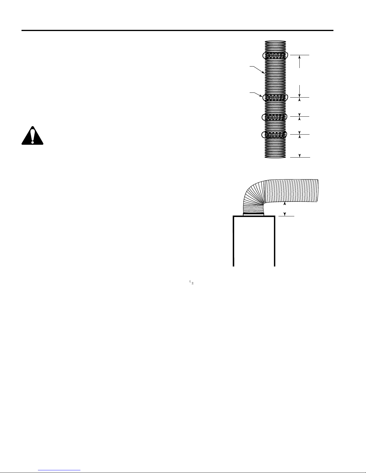
VERTICAL SIDEWALL INSTALLATION FLEX VENT PIPE
NOTE: The 40” (1016 mm) ex vent is used for 90° off the
top of the unit then out the back wall.
Follow Step 1 and 2 on Page 19.
Step 3
Install the four (4) spacer springs on the 4” ex vent pipe.
When installing the spacer springs around the 4” pipe,
stretch the spring to approximately 15” (381 mm), wrap
the spring around the pipe and interlock the ends of the
spacer spring approximately 2” (51 mm). Measure 63/4”
(172 mm) from the end of the pipe. Place the next spring
5” (127 mm) from the previously installed spring. Place
the next spring 6” (152 mm) from the last spring. Finally
place the last spring 12” (305 mm) from the last spring
installed. Figure 30
Step 4
Install the 4” (102 mm) ex vent pipe to the appliance collar as described on Page 14. Secure the end with the rst
spring 63/4” (172 mm) from the ex pipe end to the unit.
Step 5
Slide the 7” (178 mm) ex vent pipe over the 4” ex vent
pipe and secure the 7” collar as described on Page 13.
Step 6
Bend the ex pipe horizontal so the bottom of the horizontal pipe measure 61/2” (165 mm) from the top of the unit
immediately after the 90° formation. Figure 31. Be sure to
follow the 1/2” (13 mm) rise in a 12” (305 mm) horizontal
run rule.
Step 7
Install the 4” ex then 7” ex to the termination.
FP1474
6¹⁄₂" (165mm)
FP1475
Figure 31 Bend flex vent at 90° so horizontal portion is
1
6
⁄2” (165 mm) off top of unit
20
DVB Series Direct Vent Gas Fireplace
20306740
For models purchased after 4/16/15, please see addendum.
VENTING INSTALLATION
BELOW GRADE INSTALLATIONS
When it is not possible to meet the required vent terminal
clearances of 12" above grade level, a snorkel kit is recommended. It allows installation depth down to 7" (178 mm)
below grade level. The 7" (178 mm) is measured from the
center of the horizontal vent pipe as it penetrates through
the wall.
Ensure that sidewall venting clearances are observed.
If venting system is installed below ground, we recommend a window well with adequate and proper drainage
to be installed around the termination area.
If installing a snorkel, a minimum 24" vertical rise is necessary. The maximum horizontal run with the 24” vertical pipe
is 36". This measurement is taken from the collar of the
replace (or transition elbow) to the face of the exterior wall.
See the Sidewall Venting Graph for extended horizontal
run if the vertical exceeds 24".
1. Establish vent hole through the wall. Page 19, Figure
27
2. Remove soil to a depth of approximately 16" below
base of snorkel. Install drain pipe. Install window well
(not supplied). Rell hole with 12" of coarse gravel
leaving a clearance of approximately 4" below snorkel.
Figure 32
3. Install vent system.
4. Ensure a watertight seal is made around the vent pipe
coming through the wall.
5. Apply high temperature sealant caulking (supplied)
around the 4" and 7" snorkel collars.
Screws
Snorkel
Firestop
7”
Pipe
24” (610 mm)
Minimum
Drain
Foundation Wall
Figure 32 Below Grade Installation
BG402a
Minimum 4”
Clearance
Ground
Window
Well
Gravel
6. Slide the snorkel into the vent pipes and secure to the
wall.
7. Level the soil so as to maintain a 4" clearance below
snorkel. Figure 32
Do not back ll around snorkel.
A clearance of at least 4” must be maintained
between the snorkel and the soil.
If the foundation is recessed, use recess brackets (not
supplied) for securing lower portion of the snorkel. Fasten
brackets to wall rst, then secure to snorkel with self drilling
#8 x 1/2 sheet metal screws. It will be necessary to extend
vent pipes out as far as the protruding wall face. Figure 33
Snorkel
Foundation
Recess
Wall Screws
Watertight Seal
Around Pipe
FP1966
Figure 33 Snorkel Installation, Recessed Foundation
Sheet Metal
Screws
VERTICAL THROUGH-THE-ROOF
APPLICATION
his gas replace has been approved for:
• Vertical installations up to 40’ (12 m) in height. Up to
a 10’ (3 m) horizontal vent run can be installed within
the vent system using a maximum of two 90° elbows.
Figure 32
• Up to two 45° elbows may be used within the horizontal
run. For each 45° elbow used on the horizontal plane,
the maximum horizontal length must be reduced by
18” (450 mm).
Example: Maximum horizontal length:
No elbows = 10’ (3 m)
1 x 45° elbow = 8.5’ (2.6 m)
2 x 45° elbows = 7’ (2.1 m)
• A minimum of an 8’ (2.5 m) vertical rise is required.
• Two sets of 45° elbow offsets may be used within the
vertical sections. From 0 to a maximum of 8’ (2.5 m) of
vent pipe can be used between elbows. Figure 34
21
DVB Series Direct Vent Gas Fireplace
20306740
For models purchased after 4/16/15, please see addendum.
Max.Height
40’ (12.2. m)
Min. Height
8’ (2.4 m)
Max.Height
40’ (12.2. m)
Min. Height
8’ (2.4 m)
1 + 2 + 3 + 4 = 270°
Max. 10’ (3 m)
Support Straps
Every 3’ (914 mm)
Max. 10’ (3 m)
Figure 34 Support Straps for
FP1183a
Horizontal Runs
VENTING INSTALLATION
VERTICAL THROUGH-THE-ROOF
INSTALLATION
NOTE: For all top vent straight vertical through-the-roof
installations greater than 12’ (3.7 m), install the supplied
cross-bar ue restrictor onto the top edge of the rebox
ue adapter for optimal ame
appearance. Figure 36
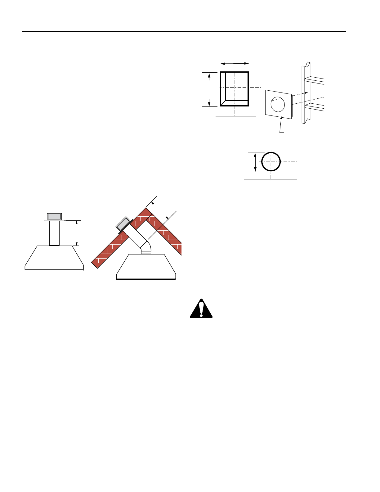
1. Locate your replace.
2. Plumb to center of the
(4”) ue collar from ceiling
above and mark position.
3.
Cut opening equal to 93/4”
x 93/4” (248 x 248 mm).
4. Proceed to plumb for additional openings through the
roof. In all cases, the opening must provide a
Figure 36 Vertical Through-the-Roof
Restrictor
minimum of 1 inch clearance to
the vent pipe, i.e., the hole must be at least 93/4” x
93/4” (248 x 248 mm).
5. Place replace into position.
6. Place restop(s) or Attic Insulation Shield into position
and secure. Figure 37
Attic Insulation
Shield
(7DV1AIS)
FP2304
1
2
3
4
1
2
3
4
Figure 35 Maximum Elbow Usage
•
7DVCS supports offsets. Figure 37. This application
FP1179
will require that you rst determine the roof pitch and
use the appropriate starter kit. (Refer to Venting Components List)
• The maximum angular variation allowed in the system
is 270°. Figure 35
• For the minimum height of the vent above the highest
point of penetration through the roof refer to Page 23,
Figure 39.
Upper Floor
11”
(279 mm)
Ceiling Installation
FP1029
Joist
Firestop
Spacer
Figure 37 Place Firestop Spacer(s) and Secure
Nails (4)
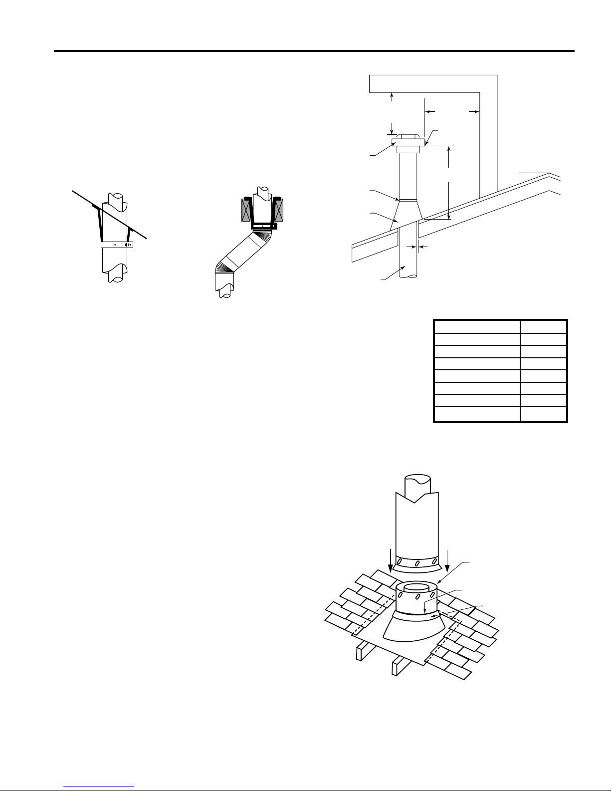
7. Install roof support (Figure 38) and roof ashing mak-
ing sure upper ange is below the shingles. Figure 40
8. Install appropriate pipe sections until the venting is
above the ashing. Figure 40
9. Install storm collar and seal around the pipe.
22
DVB Series Direct Vent Gas Fireplace
20306740
For models purchased after 4/16/15, please see addendum.
VENTING INSTALLATION
10. Add additional vent lengths for proper height. Figure
40
11. Apply high temperature sealant to 4” and 7” collars of
vertical vent termination and install.
If there is a room above ceiling level, re stop spacer must
be installed on both the bottom ad the top side of the ceiling joists. If an attic is above ceiling level an Attic Insulation Shield must be installed. The enlarged ends of the
vent section always face downward.
Typical Roof
Support
Application
Figure 38 Venting Supports
Typical Ceiling
Application
FP1184
Support
Horizontal Overhang
2 ft.
Min.
Termination
Vent
Storm Collar
Flashing
Concentric
Vent Pipe
Figure 39 Minimum Chimney Clearance
2 ft. Min.
Lowest
Discharge
Opening
H*
1” Minimum Clearance to
Combustibles
X
Roof Pitch H (feet)
Flat to 6/12 1.0
Over 6/12 to 7/12 1.25
Over 7/12 to 8/12 1.5
Over 8/12 to 9/12 2.0
Over 9/12 to 10/12 2.5
Over 10/12 to 11/12 3.25
Over 11/12 to 12/12 4.0
12
FP1971
Figure 40 Roof Flashing
*H - Minimum height from roof to
lowest discharge opening of vent
3 #5 Sheet Metal
Screws per Joint
Sealant
Storm Collar
TWL101a
23
 Loading...