

Vermont Castings 3980-399, SNV30RN, SNV30RP, 3996 Homeowner's Installation And Operating Manual
INSTALLER / CONSUMER
CER TIF IED
SAFETY INFORMATION
PLEASE READ THIS MANUAL
BEFORE INSTALLING AND USING
APPLIANCE.
WARNING!
IF THE INFORMATION IN THIS
MANUAL IS NOT FOLLOWED
EXACTLY, A FIRE OR EXPLOSION
MAY RESULT CAUSING
PROPERTY DAMAGE, PERSONAL
INJURY OR LOSS OF LIFE.
FOR YOUR SAFETY
Installation and service must be
performed by a qualified installer,
service agency or the gas suppler.
WHAT TO DO IF YOU SMELL
GAS:
• Do not try to light any appliance.
• Do not touch any electric switch; do
not use any phone in your building.
• Immediately call your gas supplier
from your neighbor’s phone. Follow
the gas supplier’s instructions.
• If you cannot reach your gas supplier,
call the fire department.
Stardance
Natural Vent Gas Heater
Model SNV30: 3980-3996
Homeowner’s Installation
DO NOT STORE OR USE
and Operating Manual
GASOLINE OR OTHER
FLAMMABLE VAPORS AND
LIQUIDS IN THE VICINITY OF THIS
OR ANY OTHER APPLIANCE.
This appliance may be installed in an
after market permanently located
manufactured (mobile) home where not
prohibited by local codes.
This appliance is only for use with the
type of gas indicated on the rating plate.
This appliance is not convertible for use
with other gases unless a certified kit is
used.
INSTALLER: Leave this manual with the appliance.
CONSUMER: Retain this manual for future reference.
20007067 1/07 Rev. 8

Stardance Natural Vent Gas Heater
Table of Contents
PLEASE READ THE INSTALLATION & OPERATING INSTRUCTIONS BEFORE USING APPLIANCE.
Thank you and congratulations on your purchase of a Vermont Castings stove.
IMPORTANT: Read all instructions and warnings carefully before starting installation. Failure to follow these
instructions may result in a possible fire hazard and will void the warranty.
Installation & Operating Instructions .........................................................................................3
Stove Dimensions ...............................................................................................................4
Clearance Requirements .....................................................................................................5
Alcove Minimum Dimensions ..............................................................................................5
Hearth Requirements ..........................................................................................................5
Gas Specifications ...............................................................................................................6
Gas Inlet and Manifold Pressures .......................................................................................6
High Elevations ...................................................................................................................6
Venting Requirements ......................................................................................................... 6
Vent Layout and Height Requirements ................................................................................6
Passing Through a Combustible Wall or Ceiling .................................................................7
Venting Requirements ......................................................................................................... 7
Installation
Unpack the Stove ................................................................................................................8
Install the Optional Fan .......................................................................................................8
Venting System Assembly ...................................................................................................9
Paint Option for Enamelled Stoves ...................................................................................10
Connect the Gas Supply Line ............................................................................................10
Burner Information ............................................................................................................. 11
Install ON/OFF Switch ....................................................................................................... 11
Thermostat Connection ..................................................................................................... 11
Install the Logset ............................................................................................................... 11
Install the Front Plate ........................................................................................................12
Operation
Your First Fire ....................................................................................................................13
Pilot and Burner Inspection ...............................................................................................13
Flame & Temperature Adjustment .....................................................................................13
Flame Characteristics ........................................................................................................13
Lighting and Operating Instructions ...................................................................................14
Troubleshooting .................................................................................................................15
Fuel Conversion Instructions ............................................................................................. 16
Maintenance
Annual System Inspection ................................................................................................. 19
Logset and Burner Cleaning and Inspection .....................................................................19
Care of Cast Iron ...............................................................................................................19
Cleaning the Glass ............................................................................................................19
Glass Replacement ...........................................................................................................19
Gasket Replacement ......................................................................................................... 20
Inspect the Vent System Annually .....................................................................................20
Check the Gas Flame Regularly .......................................................................................20
Stove Disassembly ............................................................................................................ 20
Wiring Diagrams ................................................................................................................ 21
Replacement Parts .....................................................................................................................22
Optional Accessories ..................................................................................................................25
Warranty ....................................................................................................................................... 30
Energuide ..................................................................................................................................... 32
22
20007067

General Information
Stardance Natural Vent Gas Heater
The Stardance Natural Vent Room Heater, Model Nos. 39803996 is a vented gas appliance listed to the ANSI standard
Z21.88b-2002 and CSA-2.33b-2002 for Vented Room Heaters,
and CSA 2.17-M91, Gas-Fired Appliances For Use at High Al
titudes.
The installation of the Stardance Natural Vent Room Heater
must conform with local codes, or in the absence of local codes,
with National Fuel Gas Code, ANSI Z223.1/NFPA 54 — latest edition and CSA B-149.1 Installation Code. (EXCEPTION: Do not
derate this appliance for altitude. Maintain the manifold pressure
at 3.5” w.c. for Natural Gas and 10” w.c. for LP gas at maximum
input.)
This appliance is only for use with the type of gas indicated on
the rating plate. This appliance is not convertible for use with other
gases unless a certified kit is used.
Installation and replacement of gas piping, gas utilization
equipment or accessories, and repair and servicing of equipment shall be performed only by a qualified agency. The term
“qualified agency” means any individual, firm, corporation, or
company that either in person or through a representative is
engaged in and is responsible for (a) installation or replacement of gas piping, or (b), the connection, installation, repair,
or servicing of equipment, who is experienced in such work,
familiar with all precautions required, and has complied with
all the requirements of the authority having jurisdiction.
The Stardance Natural Vent Room Heater should be
inspected before use and at least annually by a qualified
service agency. It is imperative that control compartments,
burners, and circulating air passageways of the appliance
be kept clean.
The Stardance Natural Vent Room Heater and its individual
shut-off valve must be disconnected from the gas supply piping
during any pressure testing of that system at test pressures in
excess of 1/2 psig (3.5 kPa).
The Stardance Natural Vent Room Heater must be isolated
from the gas supply piping system by closing its individual manual
shutoff valve during any pressure testing of the gas supply piping
system at test pressures equal to or less than 1/2 psig.
An accessible tap is located above the pilot/on-off knob for
checking the inlet pressure.
This appliance needs fresh air for safe operation and must be
installed so there are provisions for adequate combustion and
ventilation air.
This appliance must be properly connected to a listed 4”
(100mm) Type B venting system or to an approved masonry or
factory-built chimney system. In Canada, a complete reline of
Class A chimneys is required. This heater is equipped with a vent
safety shutoff system.
This appliance must be properly connected to a venting
system. WARNING: Operation of this heater when not connected to a properly installed and maintained venting system
or tampering with the vent safety shutoff sytem can result in
carbon monoxide (CO) poisoning and possible death.
This appliance is approved for bedroom installations in the
U.S. and Canada.
This appliance may be installed in an aftermarket* manufactured
(mobile) home, where not prohibited by state or local codes.
The Stardance Natural Vent Room Heater, when installed,
must be electrically grounded in accordance with local codes or,
in the absence of local codes, with the National Electrical Code
ANSI/NFPA 70, (latest edition), or of the current Canadian Electrical Code C22.1.
Due to high temperatures this appliance should be located
out of traffic and away from furniture and draperies.
WARNING: This appliance is hot while in operation. Keep
children, clothing, and furniture away. Contact may cause
burns or ignition of combustible materials.
Children and adults should be alerted to the hazards of high
surface temperatures and should stay away to avoid burns or
clothing ignition. Young children should be carefully super
vised when they are in the same room as the appliance.
Clothing or other flammable materials should not be placed
on or near the appliance.
Any safety screen, glass or guard removed for servicing
an appliance must be replaced prior to operating the appliance.
The appliance area must be kept clear and free from combustible materials, gasoline, and other flammable vapors
and liquids.
The flow of combustion and ventilation air must not be obstructed. The installation must include adequate accessibility
and clearance for servicing and proper operation.
WARNING: Do not operate the Room Heater with the glass
panel removed, cracked or broken. Replacement of the panel
should be done by a licensed or qualified service person.
Do not use this appliance if any part has been under water.
Immediately call a qualified service technician to inspect the
appliance and to replace any part of the control system and
any gas control which has been under water.
Do not burn wood, trash or any other material for which
this appliance was not designed. This appliance is designed
to burn either natural gas or propane only.
This gas appliance must not be connected to a chimney
flue serving a separate solid-fuel burning appliance.
CAUTION: Label all wires prior to disconnection when
servicing controls. Wiring errors can cause improper and
dangerous operation.
Verify proper operation after servicing.
* Aftermarket: Completion of sale, nor for purpose of resale,
from the manufacturer.
Proposition 65 Warning: Fuels used in gas, woodburning
or oil fired appliances, and the products of combustion of such
fuels, contain chemicals known to the State of California to
cause cancer, birth defects and other reproductive harm.
California Health & Safety Code Sec. 25249.6
-
20007067
3
Stardance Natural Vent Gas Heater
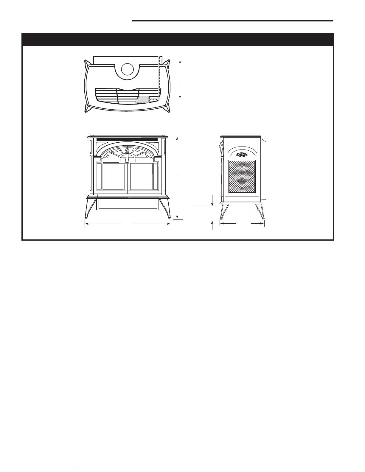
9"
(229mm)
C
L
Valve
Inlet
26"
(680 mm)
25"
(635 mm)
14"
(355 mm)
3"
(76 mm)
C
L
Valve Inlet
Stardance Natural Vent Gas Heater Dimensions
See Page 5 for Flue Collar
Centerline Dimensions.
Fig. 1 Stardance dimensions.
4406
44
20007067
Stardance Natural Vent Gas Heater
C
L
C
L
C
D
B
A
A
A
B
B
72"
(1829mm)
45"
(1140mm)
B
A
A
C
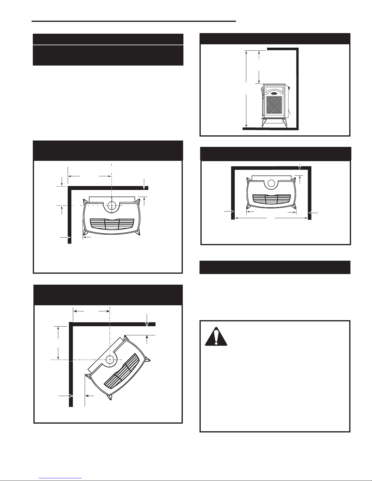
Clearance Requirements
Minimum Clearances to
Combustible Materials
Measure side clearances as shown in Figures 2
through 5 from the outer edge of the cast iron stove top.
Measure rear clearances from the outermost surface of
the sheet metal rear skirt.
The Stardance heater is approved for installation into
an alcove constructed of combustible materials to the
dimensions and clearances shown on the next page.
The same clearances apply in a standard parallel instal
lation.
Parallel Installation: Minimum Clearance
and Flue Centerline
Ceiling Clearances
-
ST657
Fig. 4 Minimum ceiling clearance; minimu alcove height.
Alcove Minimum Dimensions
Stove Clearances A: 5” (125mm)
B: 4” (102mm)
Pipe Centerlines C: 16” (406mm)
D: 9¹⁄₄” (235mm)
Fig. 2 Parallel installation requirements.
Corner Installation: Minimum Clearance and
Flue Centerline
Stove Clearance A: 4” (102mm)
Pipe Centerline B: 17” (432mm)
Fig. 3 Corner installation requirements.
20007067
ST128b
ST129b
A: 4” (102mm)
B: 33” (838mm)
C: 5” (125mm)
Fig. 5 The Stardance Natural Vent Stove is approved for
installation into alcoves built of combustible materials.
ST658
Hearth Requirements
The Stardance Heater must be installed on rigid flooring. When the heater is installed directly on any combustible surface other than wood flooring, a metal or
wood panel extending the full width and depth of the
unit must be used as the hearth. There are no other
hearth requirements.
WARNING:
• Always maintain required clearances
(air spaces) to nearby combustibles
to prevent fire hazard. Do not fill air
spaces with insulation. All venting compo
nents must maintain a 1” (25 mm) clearance to
combustible materials. Maintain a 6” (152 mm)
c
learance when using single wall pipe.
• The gas appliance and vent system must be
vented directly to the outside of the building
and never be attached to a chimney serving a
separate solid fuel or gas-burning appliance.
• Refer to the manufacturer’s instructions in
cluded with the venting system for complete
installation procedures.
-
-
5
Stardance Natural Vent Gas Heater
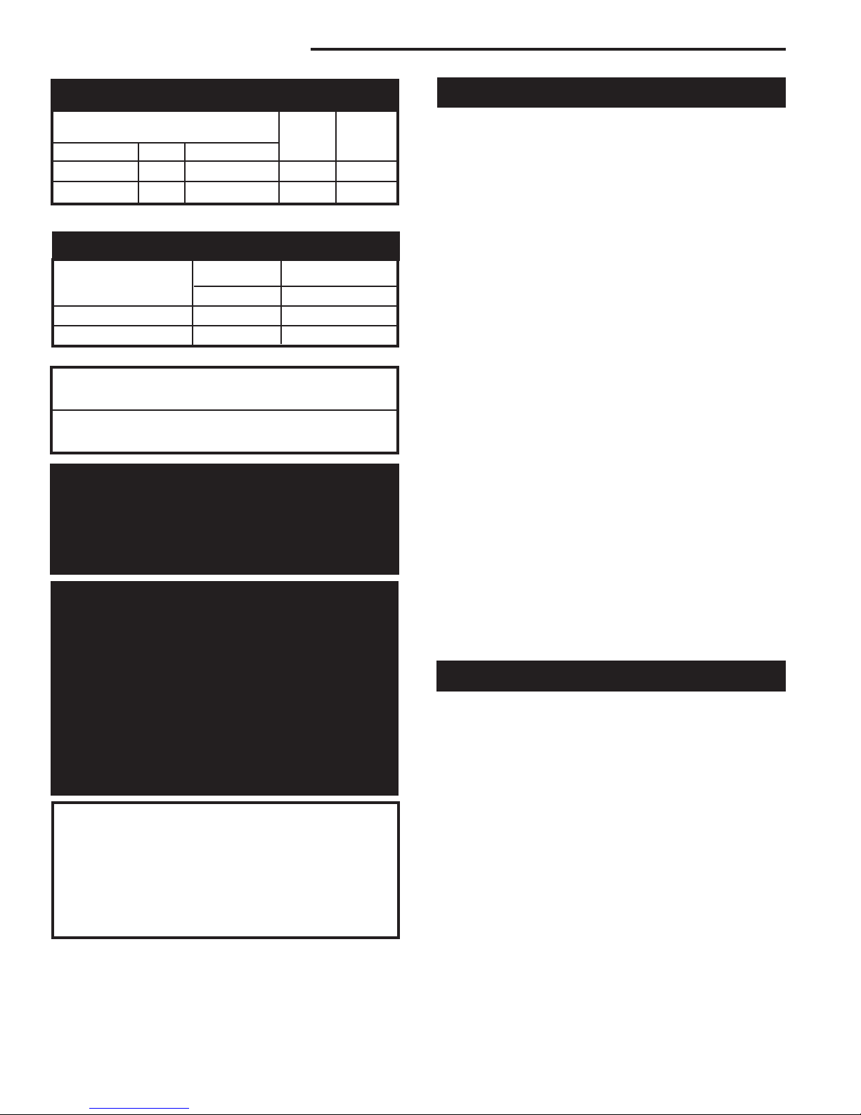
Gas Specifications
Max. Min.
Input Input
Model Fuel Gas Control BTU/h BTU/h
SNV30RN Nat Millivolt 28,000 19,000
SNV30RP Prop Millivolt 28,000 21,500
Weight: Fully assembled 350 lbs.
Gas Inlet and Manifold Pressures
Natural LP (Propane)
Inlet Minimum 5.5” w.c. 11” w.c.
Inlet Maximum 14” w.c. 14” w.c.
Manifold Pressure 3.5” w.c. 10” w.c.
Stardance Natural Vent
Certified to:
ANSI Z21.88-2005 / CSA Z2.33-2005
Vented Gas Fireplace Heaters
The installation must conform with local codes or, in
the absence of local codes, with the National Fuel Gas
Code, ANSI Z223.1/NFPA 54 - latest edition. (EXCEPTION: Do not derate this appliance for altitude. Maintain the manifold pressure at 3.5” w.c. for Natural Gas
and 10” w.c. for Propane.)
High Elevations
Input ratings are shown in BTU per hour and are
certified without deration for elevations up to
4,500 feet (1,370m) above sea level.
For elevations above 4,500 feet (1,370m) in USA,
installations must be in accordance with the
current ANSI Z223.1/NFPA 54 and/or local codes
having jurisdiction.
In Canada, please consult provincial and/or local
authorities having jurisdiction for installations at
elevations above 4,500 feet (1,370m).
WARNING: Improper installation, adjustment, alteration, service or maintenance
can cause injury or property damage. Refer
to this manual for correct installation and
operational procedures. For assistance or
additional information consult a qualified
installer, service agency, or the gas supplier.
Venting Requirements and Options
The Stardance must be properly connected to a listed
4” (102 mm) Type B venting system or to an approved
Class A masonry or factory-built chimney system. In
Canada, a complete relining of Class A chimney systems is required.
The Stardance Natural Vent stove will accept decorative 6” (152 mm) stove pipe around the Type B venting
system, for aesthetic purposes.
Complete Type B vent systems are available from a
number of manufacturers, and your dealer can usually
supply one. Pipe sections from different makers are not
interchangeable; do not mix pipe or vent sections from
different makers. Follow the vent system manufacturer’s instructions.
The vent system should conform to the specifications of
the National Fuel Gas Code, latest edition.
If connecting to a Class A chimney system, use 4” (102
mm) single wall or 4” Type B vent connector. Single wall
vent connector requires a minimum 6” (152 mm) clearance to combustible surfaces.
Exterior chimneys may be subject to flow reversal or
condensation. To lessen these conditions, enclose Type
B vents in an insulated chase, or reline exterior Class A
chimneys.
An approved pass-through device is always required,
whether the vent system passes through a wall or
a ceiling. Use a pass-through device from the same
maker who supplies the venting system.
Venting terminals shall not be recessed into a wall or
siding.
Vent Layout and Height Requirements
Venting for a Stardance can rise vertically through the
home, or can pass through an exterior wall and rise
along the outside of the home. Some codes require that
a Type B vent system rising on the outside of the home
be enclosed in a chase. Check your local codes for
requirements.
The minimum vent system height for the Stardance
Natural Vent Stove is 8’ (2.43 m), (Fig. 7) measured
from the top of the stove. To determine the minimum
height the vent system must extend through or past the
roof, refer to the 1993 edition of the National Fuel Gas
Code.
66
20007067
Stardance Natural Vent Gas Heater
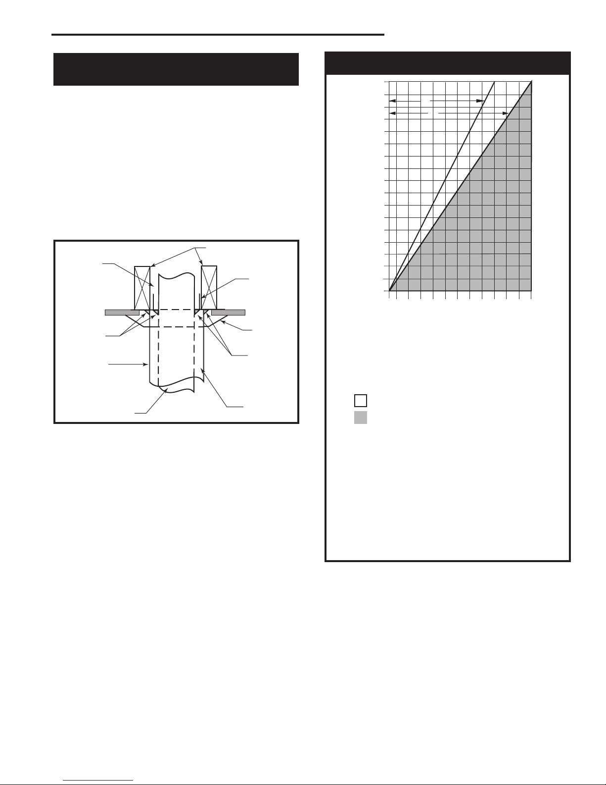
Venting Runs
A: Vertical installations up to 36 feet (12m) in
height. Up to an 18 ft. horizontal vent run can be
installed within the vent system using a
maximum of two 90-degree elbows or four
45-degree elbows.
B: Vertical installations up to 36 feet (12m) in
height. Up to a 24 ft. horizontal vent run can be
installed within the vent system using a
maximum of two 45-degree elbows.
(Ratio = 2/3, Hor./Vert.)
= Acceptable venting configuration
= Unacceptable venting configuration
NOTE: When venting staight vertical, without an
elbow, a minimum of 8 ft. vertical is required
off the top of the stove.
Horizontal Run (in feet)
Vertical Run (in feet)
(Measured from top of the unit before any elbow)
36
34
32
30
28
26
24
22
20
18
16
14
12
10
8
6
4
2
1 2 4 6 8 10 12 14 16 18 20 22 24
A
B
Passing Through a
Venting Requirements
Combustible Wall or Ceiling
An approved pass-through device is always required
when a vent passes through a combustible wall or ceiling. Check with the maker of the vent system for the
correct listed devices that are available. A listed passthrough device is required whether or not the installation includes decorative pipe around the Type B venting
system. NOTE: It is essential to seal between the ceiling support (sometimes called a ‘firestop spacer’) and
the decorative pipe, if installed, with a high-temperature
silicone sealant. (Fig. 6)
Complete the venting system installation according to
the manufacturer’s instructions.
Air Space as Required by Code
High-temperature Silicone
Sealant
Decorative
6” Pipe
Listed 4”
ST361
(102 mm)
B-Vent
Fig. 6 A ceiling pass-through, with decorative pipe around the
vent.
Joists
Ceiling
Support
Trim Col
lar
High-temperature
Silicone
Sealant
Air Space
-
20007067
FP567b
Fig. 7 Vent termination window.
7
Stardance Natural Vent Gas Heater
Installation
Unpack the Stove
The Stardance is shipped fully assembled on its back.
Unpack the stove and carefully set it upright.
CAUTION
Porcelain enamelled surfaces are fragile. Handle
porcelain enamelled castings tenderly. Familiarize
yourself with the assembly steps before you begin
and proceed with deliberation and care. If possible,
have assistance available.
Place enamelled castings on a soft, cushioned surface until you are ready to assemble.
Avoid contact between the castings and other hard
surfaces or objects.
Install the Optional Fan
WARNING
This appliance is equipped with a three-prong
(grounded) plug for your protection against shock
hazard and should be plugged directly into a
properly grounded three-prong receptacle. Do not
cut or remove the grounding prong from this plug.
If you are installing the optional convection Fan Kit
#2767 (FK26), continue here. If you are not installing a
fan kit, proceed to Venting System Assembly.
1. The fan kit includes a blower assembly and a rheo
stat assembly, connected by a cable. The blower assembly mounts to the bottom rear of the stove, and
the rheostat mounts to the left side of the valve. The
assembly includes a ‘snapstat’ which automatically
turns the fan ON (or OFF) above (or below) approximately 109°F. The rheostat also provides a range
of fan speed settings from Off (which overrides the
snapstat function) to High. Unpack and inspect the
blower assembly. Confirm that the fan spins freely.
2. Remove the rear shroud by loosening the two (2)
bolts at the bottom left and right side of the shroud.
Slide shroud straight up, rotate the bottom out and
away from stove and pull shroud out.
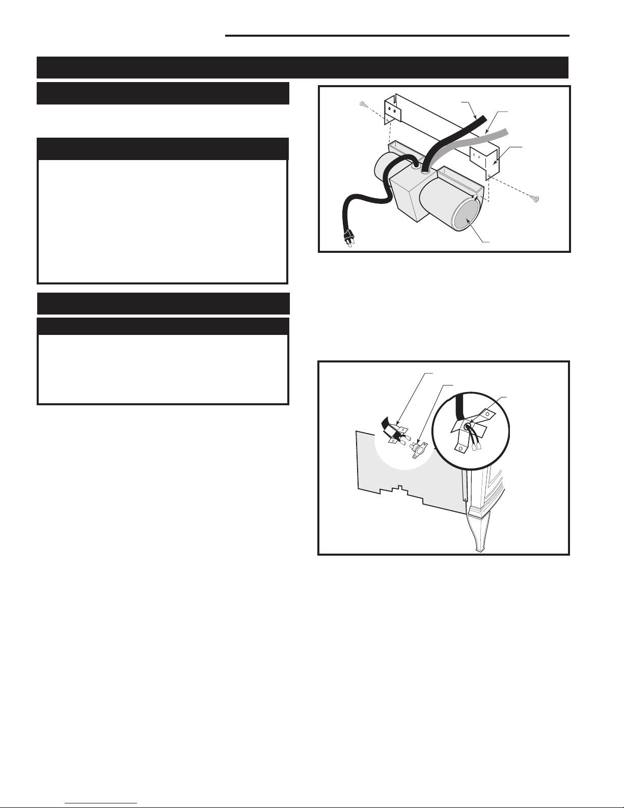
3. Attach the fan assembly to the fan bracket provided
in the log box. Use #10 sheet metal screws provided
in fan kit. Do not remove finger guard screws. (Fig.
8)
Snapstat
Wire
Rheostat Wire
Fan Bracket
ST669
Fig. 8 Attach the fan assembly to the fan bracket.
Finger Guard
4. Connect snapstat leads. Disconnect the snapstat
module from the leads inside the snapstat bracket.
(Fig. 9) Bend open the snapstat bracket. Use needle
nose pliers to remove the black plastic grommet
from the bracket. Discard the bracket. Connect
the two wires to the two snapstat extension leads
located between the inner and outer shroud.
Snapstat Bracket
Snapstat Module
Pinch
Grommet to
Remove
-
ST670
Fig. 9 Remove the snapstat and grommet from the bracket
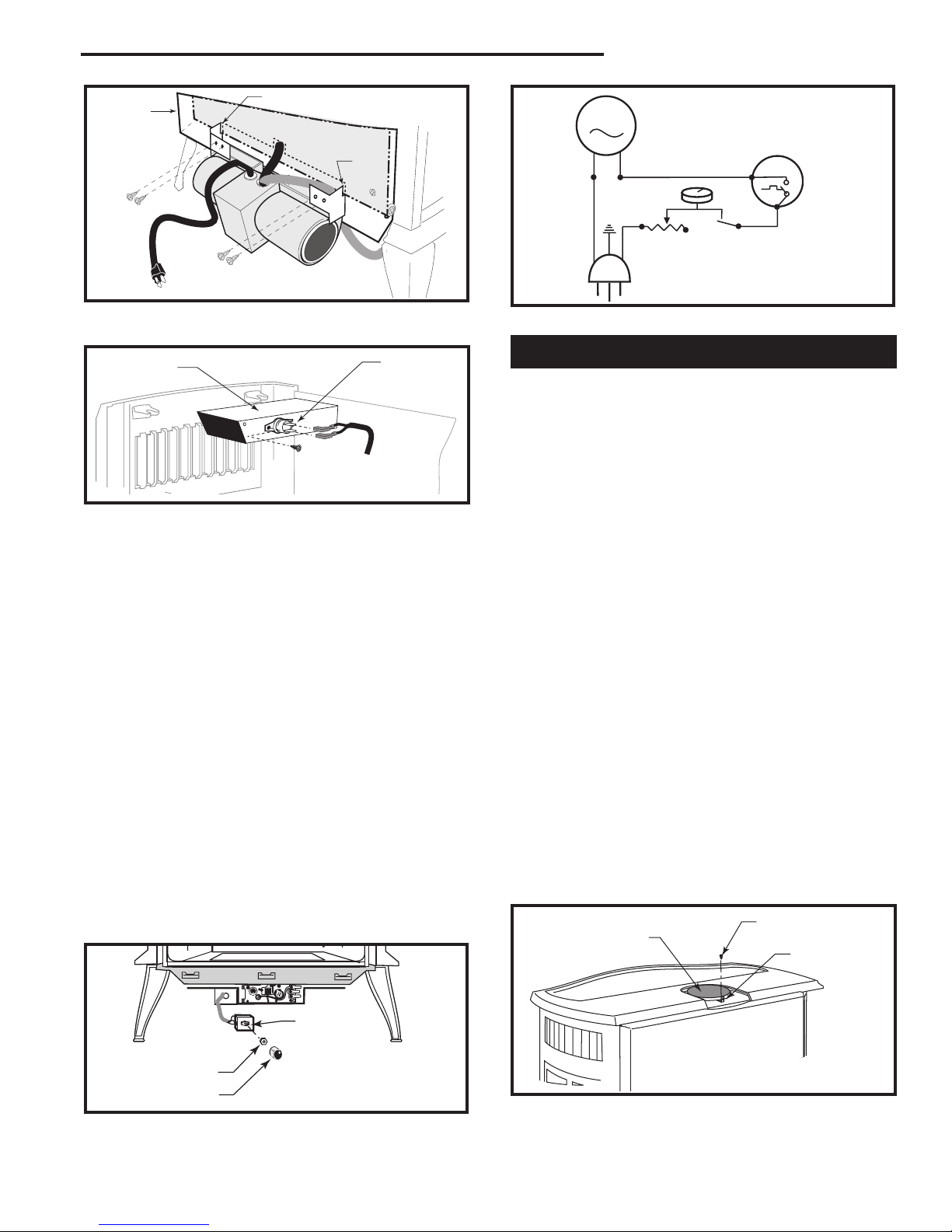
5. Position the fan assembly so the ducts slide be
tween the inner and outer shroud. The inner shroud
should engage with the two slots in the ends of the
bracket so the bracket and shroud are interlocked.
(Fig. 10) Secure the bracket with the four sheet
metal screws provided in the finish bag.
6. Install the snapstat by loosening the front screw on
the inner side of the duct. (Fig. 11) Slide the snapstat
under the head of the screw and tighten. Connect
the leads to the snapstat. Make sure the snapstat
assembly is mounted straight front to back.
7. Reattach rear shroud assembly in reverse order of
Step 2. Tighten bottom bolts to hold shroud in place.
88
20007067
Stardance Natural Vent Gas Heater
MOTOR
SNAPSTAT
ON/OFF
RHEOSTAT
WHT
WHT
BLK
BLK
BLK
GRN
BLK
POWER
Outer
Shroud
ST194
Slot
Inner Shroud
Slot
Fig. 10 Position the fan to engage the inner shroud with the
fan bracket slots and secure with sheet metal screws.
Left Air Duct
NOTE: Shown without
top for clarity.
Snapstat
ST671
Fig. 11 Install the snapstat and connect the extension wire
terminals. View is with top removed, however, access is available through the grille opening.
8. The rheostat control switch attaches to the left side
of the valve bracket at the front of the stove. (Fig.
12)
• Remove retaining nut from shaft of rheostat. (if
preinstalled)
• Insert the rheostat through the hole in the back
of the left side of the valve bracket, aligning the
locator pin with the smaller hole in that bracket.
• Thread the retaining nut onto the shaft of the
rheostat, tightening with a wrench. Do not overtighten.
• Attach the control knob to the rheostat shaft.
• Use the wire tie to secure the fan and rheostat
wire harnesses together.
9. Plug the power cord into a standard grounded 110
volt household outlet. If the fan control knob is not
turned to the OFF position, the fan will turn on when
the temperature at the snapstat reaches approximately 109°F.
ST196
Fig. 13 #2767 / FK26 fan wiring diagram.
Venting System Assembly
Adjust the leg levelers as needed. They should not
extend any further from the leg than necessary.
The venting collar is on the sheet metal draft hood/heat
exchanger assembly, over the firebox. Use a B-vent
adapter, from the same maker as the rest of the B-vent
components, to join the first section of venting to the
draft hood.
The SNV30 stove includes a spill switch. Operating this
stove when not connected to a properly installed and
maintained venting system, or tampering with or disconnecting the spill switch, can result in carbon monoxide
(CO) poisoning and possible death.
The stove includes a bracket for installing decorative 6”
(152mm) round stove pipe around the B-vent, for appearance purposes only. The decorative pipe need not
be concentric with the vent pipe.
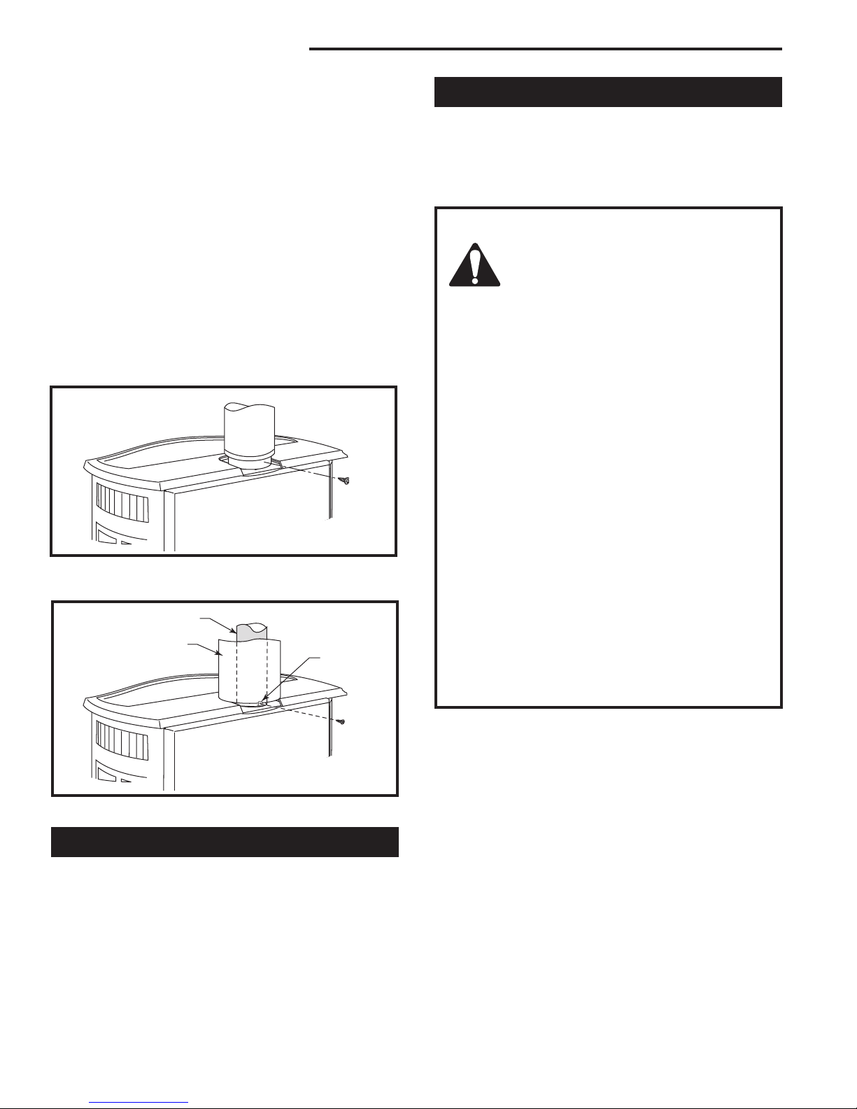
If the installation includes decorative stove pipe around
the venting system, make a cardboard template of the
decorative pipe by tracing its circumference. Put this
template in the flue recess in the stove top. Position the
template to fit well against the front of the recess. (Fig.
14) Use this template to locate the bracket to hold the
decorative pipe. Depending on spacing, the bracket
may fit inside the decorative pipe without interfering
with the vent system. Fasten the bracket to the draft
hood/heat exchanger assembly with a sheet metal
screw.
Sheet Metal Screw
Template
Bracket
Retaining Nut
Control Knob
Fig. 12 Attach rheostat to left side of valve.
20007067
ST347a
ST372
Fig. 14 Use a template to locate the bracket for decorative
pipe to surround the B-vent pipe.
9
Stardance Natural Vent Gas Heater
Insert the B-vent adapter into the flue collar and drill
1/8” (3mm) pilot holes through both the stove’s collar
and the adapter. Attach the adapter to the flue collar
with sheet metal screws. (Fig. 15)
Attach the first section of venting to the B-vent adapter.
Depending on the length of the individual venting
sections and the lengths of the decorative pipe, you
may need to slip the decorative pipe over the venting
sections before attaching upper sections to lower ones.
The sections of decorative pipe should be oriented with
their seams (if any) toward the wall; sections usually
do not need to be fastened at each joint, other than slip
sections. The decorative pipe need not be fastened to
the locating bracket on the stove. If the layout includes
a slip section, this should be the last section of pipe visible in the room at the ceiling. Refer to Page 7, Figure 6
for details on joining the decorative pipe at the ceiling.
Connect the Gas Supply Line
Check the Rating Plate attached by a steel cable to the
firebox, to confirm that you have the appropriate firebox
for the type of fuel to be used. The Stardance may be
converted from one gas to another using the appropriate Fuel Conversion Kit listed on Page 24.
CAUTION
This appliance should only be connected by a qualified gas technician. Test to
confirm manifold pressures as specified
below.
The Stardance Heater and its individual shutoff
valve must be disconnected from the gas supply
piping during any pressure testing of that system
at test pressures in excess of 1/2 psig (3.5 kPa).
The Stardance Heater must be isolated from the
gas supply piping system by closing its individual manual shutoff valve during any pressure
testing of the gas supply piping system at test
pressure equal to or less than 1/2 psig.
ST373
Fig. 15 Attach the B-vent adapter to the flue.
B-vent Pipe
Decorative
Pipe 7FSSK
Fig. 16 Install decorative pipe over the B-vent pipe.
Bracket
ST374
Paint Option for Enamelled Stoves
If you wish to match the decorative or vent pipe to the
color of the stove, paint the pipe before installation. Use
only a high-temperature paint. Paint only in a well-ventilated area. Mask the surroundings to prevent overspray.
Apply the paint lightly; two light coats will result in a
better finish than a single heavy coat. Let the paint dry
thoroughly before handling painted parts.
There must be a gas shutoff between the stove
and the supply.
In order to connect Natural Gas, use a fitting with
3/8” NPT nipple on the valve side and 1/2” natural
gas supply line with an input of 28,000 BTUs at
a manifold pressure of 3.5” and a minimum inlet
supply pressure of 5.5” w.c.
In order to connect Propane, use a fitting with
3/8” NPT nipple on the valve side and 1/2” propane gas supply line with an input of 26,000
BTUs at a manifold pressure of 10.0” and a minimum inlet supply pressure of 11.0” w.c.
In the U.S.; Gas connection should be made in ac-
cordance with current National Fuel Gas Code, ANSI
Z223.1/NFPA 54. Since some municipalities have
additional local codes, be sure to consult you local
authority.
In Canada; consult the local authority and CSA-B149.1
installation code.
Connect the gas supply and test for leaks. Use a 50/50
solution of liquid soap and water to test for leaks at gas
fittings and joints. Apply water/soap solution with brush
only - do not over apply. NEVER test with an open
flame. Light the pilot according to the directions on
Page 14, before going to the next step.
1010
20007067
 Loading...