

Vermont Castings 33CFDVNV, 33CFDVPV, 33CFDVPI, 36CFDVNV, 36CFDVPV Installation And Operating Instructions Manual
...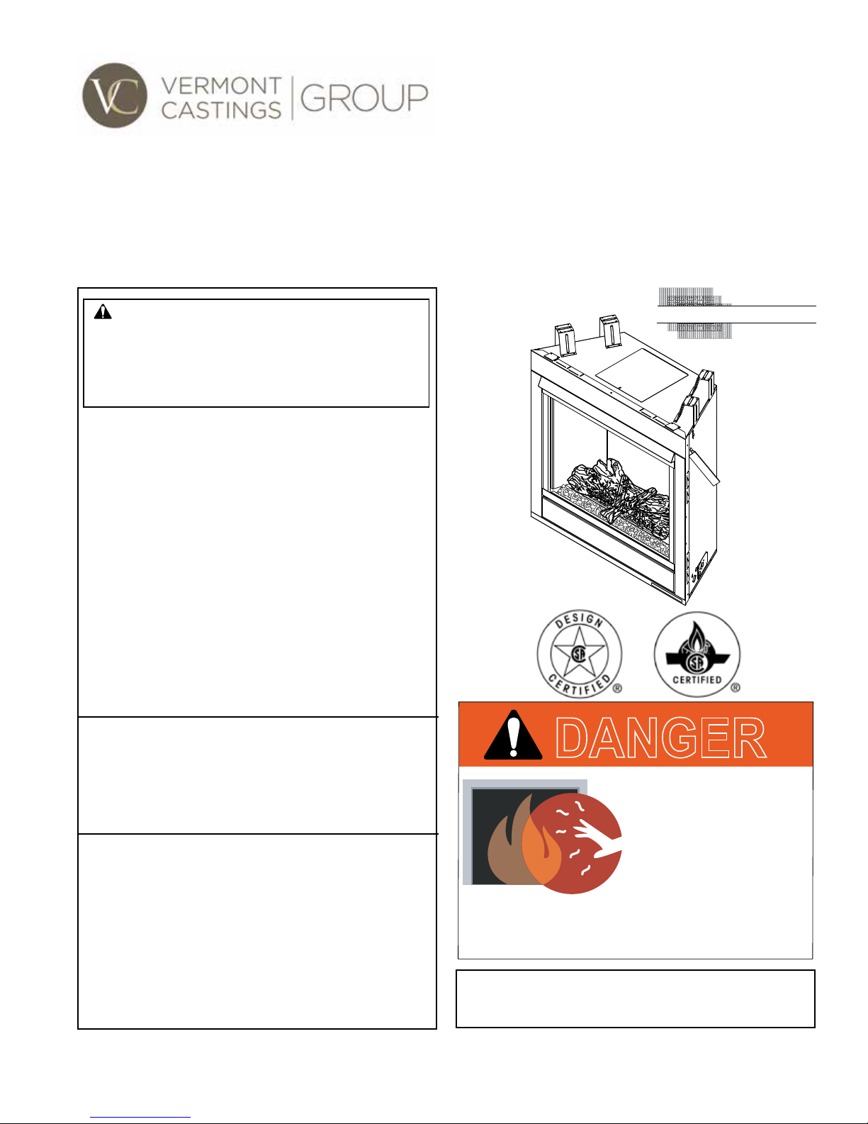
CFDV Series Direct Vent Gas Fireplace
S
Installation and Operating Instructions
Models: 33CFDV(N/P)(V/I)SL, 36CFDV(N/P)(V/I)SL, 42CFDV(N/P)(V/I)SL
WARNING:
FIRE OR EXPLOSION HAZARD
Failure to follow safety warnings exactly
could result in serious injury, death or
property damage.
• Do not store or use gasoline or other
ammable vapors and liquids in the
vicinity of this or any other appliance.
• WHAT TO DO IF YOU SMELL GAS
– Do not try to light any appliance.
– Do not touch any electrical switch; do
not use any phone in your building.
– Leave the building immediately.
– Immediately call your gas supplier from
a neighbor's phone. Follow the gas
supplier's instructions.
– If you cannot reach your gas supplier,
call the re department.
• Installation and service must be performed
by a qualied installer, service agency or
the gas supplier.
WARNING: Improper installation, adjustment,
alteration, service or maintenance can cause
injury or property damage. Refer to this manual.
For assistance or additional information consult
a qualified installer, service agency or the
gas supplier.
This appliance may be installed in an aftermarket,*
permanently located, manufactured home (USA
only) or mobile home, where not prohibited by
local codes.
This appliance is for use only with the type of gas
indicated on the rating plate. This appliance is
not convertible for use with other gases, unless
a certied kit is used.
* Aftermarket: Completion of sale, not for purpose of resale, from
the manufacturer.
CERTIFIED
AFETY BARRIER
DANGER
HOT GLASS WILL
CAUSE BURNS.
DO NOT TOUCH GLASS
UNTIL COOLED.
NEVER ALLOW CHILDREN
TO TOUCH GLASS.
A barrier designed to reduce the risk of burns from
the hot viewing glass is provided with this
appliance and shall be installed.
INSTALLER: Leave this manual with the appliance.
CONSUMER: Retain this manual for
future reference.
20306739 1115 Rev. 2

CFDV Series Gas Fireplace
CONTENTS
PLEASE READ THE INSTALLATION & OPERATING INSTRUCTIONS
BEFORE USING APPLIANCE.
Thank you and congratulations on your purchase of a Vermont Castings Group replace.
IMPORTANT: Read all instructions and warnings carefully before starting installation.
Failure to follow these instructions fully may result in a possible re hazard and will void the warranty.
Important Safety Information .............................................................3
Code Approval .....................................................................................4
Product Features ................................................................................. 5
Product Specications ................................................................... 5
Gas Specications & Orice Sizes ................................................ 5
Gas Pressures ............................................................................... 5
High Elevations .............................................................................5
Cold Climate Insulation .................................................................5
Battery Back Up Kit .......................................................................6
Pre-Installation Information ................................................................ 7
Before You Start ............................................................................7
Items Required for Installation ....................................................... 7
Fireplace Framing ........................................................................7
Fireplace & Framing Dimensions ..................................................8
Fireplace Location ......................................................................... 9
Clearances ...........................................................................................9
Clearances to Combustibles .........................................................9
Mantel Clearances ......................................................................10
Fireplace Installation ......................................................................... 10
Secure Fireplace to Floor or Framing .......................................... 10
Finishing Material ........................................................................10
Venting Installation Information ....................................................... 11
Optional Top Vent Application ...................................................... 11
Installation Precautions ...............................................................13
General Venting ..........................................................................13
Termination Location ........................................................... 14
Termination Clearances.......................................................15
Assembling Vent Pipe .................................................................15
How to Use the Vent Graph .........................................................16
SLP Pipe......................................................................................16
Additional Assembly Instructions ................................................. 17
Disassemble Vent Sections .........................................................18
Vent Pipe Clearances ..................................................................17
Inner Flex Vent Pipe ...................................................................19
SLP-RVTM - Horizontal Termination Kit ...................................... 20
Horizontal Termination Kit............................................................ 20
Rear Wall Vent Installation—Flex Vent Pipe ................................21
Top Vent Side Wall Application .................................................... 21
Vertical Side Wall Applications ....................................................23
Vertical Side Wall Installaion ....................................................... 23
SLP-HSFTK - Horizontal Termination Kit..................................... 25
Below Grade Installation .............................................................26
Vertical Through-the-Roof Application .........................................27
Vertical Through-the-Roof Installation .........................................28
Attic Shield Installation ................................................................30
Roof Support Installation ............................................................. 30
Vertical Termination Kit Installation ..............................................32
Attaching Flex Vent to Vertical Termination Kit ............................32
Gas Pipe Installation ......................................................................... 33
Check Gas Type ..........................................................................33
Installation Items Needed ............................................................ 33
Gas Pipe Installation ...................................................................34
Check Gas Pressure – Millivolt ...................................................34
Electrical Installation – Millivolt ....................................................... 35
Electrical Wiring ........................................................................... 35
Remote Wall Mounted Switch .....................................................36
Optional DC Remote Systems ....................................................36
Optional Fan/Blower System BLOT.............................................37
Optional Fan/Blower System FK12 .............................................37
Operating Instructions – Millivolt .....................................................38
For Your Safety Read Before Lighting ......................................... 38
What To Do If You Smell Gas ......................................................38
Lighting Pilot for the First Time ....................................................38
Lighting Pilot ................................................................................ 39
Lighting Burner ............................................................................ 40
To Turn Off Gas ...........................................................................40
Check Gas Pressure and Electrical Installation – IPI ..................... 41
Electrical Wiring ........................................................................... 41
Junction Box Wiring ..................................................................... 42
Wall Switch Installation ................................................................42
IPI System Wiring Diagram .........................................................43
Operating Instructions – IPI ..............................................................44
For Your Safety Read Before Lighting ......................................... 44
What To Do If You Smell Gas ......................................................44
Operating Instructions .................................................................45
To Turn Off Gas ...........................................................................45
EcoLogic Control System Operation and Indications .................. 46
Final Installation ................................................................................ 47
Glass Frame Removal ................................................................. 47
Pilot Flame ..................................................................................48
Burner Flame ............................................................................... 48
Installing Porcelain Liner Kit ........................................................ 48
Installing Brick Liner Kit ............................................................... 49
Rockwool Placement ................................................................... 49
Adjustable Bafe .........................................................................50
Log Placement ............................................................................50
Lava Rock and Ember Placement ............................................... 51
Fireglass and Stone Placement ..................................................52
Fireglass Only Placement ...........................................................53
Safety Barrier Installation ............................................................53
Safety, Cleaning and Maintenance ...................................................54
Burner, Pilot and Control Compartment ......................................54
Burner .......................................................................................... 54
Vent System ................................................................................54
Glass Frame ................................................................................ 54
Logs ............................................................................................54
Rock Wool ..................................................................................54
Stones and Fireglass ................................................................... 54
Troubleshooting ................................................................................55
Millivolt Standing Pilot Ignition ..................................................... 55
IPI System ................................................................................... 56
All Control/Pilot Systems ............................................................. 57
Optional Accessories ........................................................................ 57
Replacement Parts ............................................................................ 58
Firebox Components ................................................................... 58
Logs ............................................................................................58
Standing Pilot – Millivolt Control .................................................. 59
IPI System ................................................................................... 60
Venting Components .........................................................................61
Massachusetts Requirements .......................................................... 64
Limited Lifetime Warranty Policy .....................................................65
Efciency Ratings .............................................................................68
2
20306739
IMPORTANT SAFETY INFORMATION
CFDV Series Gas Fireplace
INSTALLER
Please leave these instructions with the appliance.
OWNER
Please retain these instructions for future reference
WARNING:
• Read this owner’s manual carefully and completely before trying to assemble, operate, or service this
replace.
• Any change to this replace or its controls can be dangerous.
• Improper installation or use of this replace can cause serious injury or death from re, burns,
explosions, electrical shock and carbon monoxide poisoning.
This replace is a vented product. This replace must be
properly installed by a qualied service person. The glass
door must be properly seated and sealed. If this unit is not
properly installed by a qualied service person with glass
door properly seated and sealed, combustion leakage can
occur.
CARBON MONOXIDE POISONING: Early signs of carbon
monoxide poisoning are similar to the u with headaches,
dizziness and/or nausea. If you have these signs, the re-
place may not have been installed properly. Get fresh air
at once! Have the replace inspected and serviced by a
qualied service person. Some people are more affected
by carbon monoxide than others. These include pregnant
women, people with heart or lung disease or anemia,
those under the inuence of alcohol, and those at high
altitudes.
Propane/LP gas and natural gas are both odorless. An
odor-making agent is added to each of these gases. The
odor helps you detect a gas leak. However, the odor added
to these gases can fade. Gas may be present even though
no odor exists.
Make certain you read and understand all warnings. Keep
this manual for reference. It is your guide to safe and proper
operation of this replace.
1. Installation and repair should be done by a qualied
service person. The appliance should be inspected
before use and at least annually by a professional
service person. More frequent cleaning may be
required due to excessive lint from carpeting,
bedding material, et cetera. It is imperative that
control compartments, burners and circulating air
passageways of the appliance be kept clean.
2. This appliance is only for use with the type of gas
indicated on the rating plate. This appliance is not
convertible for use with other gases unless a certied
kit is used.
3. For propane/LP replace, do not place propane/LP
supply tank(s) inside any structure. Locate propane/LP
supply tank(s) outdoors. To prevent performance problems, do not use propane/LP fuel tank of less than 100
lbs. capacity.
4. If you smell gas:
• Shut off gas supply.
• Do not try to light any appliance.
• Do not touch any electrical switch; do not use any
phone in your building .
• Immediately call your gas supplier from a neighbor’s
phone. Follow the gas supplier’s instructions.
5. Never install the replace:
• In a recreational vehicle
• Where curtains, furniture, clothing, or other am-
mable objects are less than 36" from the front, top,
or sides of the replace
• In high trafc areas
• In windy or drafty areas
6. Due to high temperatures, the appliance should be
located out of trafc and away from furniture and
draperies.
7. This replace reaches high temperatures. Children
and adults should be alerted to the hazards of high
surface temperature and should stay away to avoid
burns or clothing ignition. Fireplace will remain hot
for a time after shutdown. Allow surfaces to cool before
touching.
8. Young children should be carefully supervised
when they are in the same room as the appliance.
Toddlers, young children and others may be susceptible to accidental contact burns. A physical
barrier is recommended if there are at risk individuals in the house. To restrict access to a replace
or stove, install an adjustable safety gate to keep
toddlers, young children and others at risk individuals out of the room and away from hot surfaces.
9. Clothing or other ammable material should not be
placed on or near the appliance.
10. When the appliance is installed directly on carpeting, tile
or other combustible material other than wood ooring,
you must set appliance on a metal or wood panel or
hearth pad extending the full width and depth of the
appliance.
.
20306739
3
CFDV Series Gas Fireplace
IMPORTANT SAFETY INFORMATION
11. Do not modify replace under any circumstances. Any
parts removed for servicing must be replaced prior to
operating replace.
12. Turn replace off and let cool before servicing, installing, or repairing. Only a qualied service person should
install, service, or repair the replace. Have burner
system inspected annually by a qualified service
person.
13. You must keep control compartments, burners, and
circulating air passages clean. More frequent cleaning
may be needed due to excessive lint and dust. Turn off
the gas valve and pilot light before cleaning replace.
14. Have venting system inspected annually by a quali-
ed service person. If needed, have venting system
cleaned or repaired. Refer to Cleaning and Maintenance section of this manual.
15. Keep the area around your replace clear of combustible materials, gasoline, and other ammable vapor
and liquids. Do not run replace where these are used
or stored. Do not place items such as clothing or deco-
rations on or around replace.
16. Do not use this replace to cook food or burn paper or
other objects.
17. Never place anything on top of replace.
18. Do not use any solid fuels (wood, coal, paper, card-
board, etc.) in this replace. Use only the gas type
indicated on rating plate.
19. This appliance, when installed, must be electrically
grounded in accordance with local codes or in the
absence of local codes, with the National Electrical
Code, ANSI/NFPA 70, or the Canadian Electrical Code,
CSA C22.1.
20. Do not obstruct the ow of combustion and ventilation
air in any way. Provide adequate clearances around
air openings into the combustion chamber along with
adequate accessibility clearance for servicing and
proper operation.
21. Do not use replace if any part has been under water.
Immediately call a qualified service technician to
inspect the appliance and to replace any part of the
control system and any gas control which has been
under water.
22. Do not operate replace if any log is broken.
23. Do not use a blower insert, heat exchanger insert, or
any other accessory not approved for use with this
replace.
24. Do not operate appliance with the glass front
removed, cracked, or broken. Replacement of the
glass should be done by a licensed qualied ser-
vice person.
CODE APPROVAL
Direct Vent type appliances draw all combustion air from
outside of the dwelling through the vent pipe.
These appliances have been tested by CSA and found to
comply with the established standards for DIRECT VENT
GAS FIREPLACE HEATERS in the USA and Canada as
follows:
LISTED VENTED GAS FIREPLACE HEATER
TESTED TO:
ANSI Z21.88-2015/CSA 2.33-2015 STANDARDS
The installation must conform with local codes or, in the
absence of local codes, with the National Fuel Gas Code,
ANSI Z223.1/NFPA 54, or the National Gas and Propane
Installation Code, CSA B149.1.
A manufactured home (USA only) or mobile home OEM
installation must conform with the Manufactured Home
Construction and Safety Standard, Title 24 CFR, Part 3280,
or when such a standard is not applicable, the Standard for
Manufactured Home Installations, ANSI/NCSBCS A225.1,
or Standard for Gas Equipped Recreational Vehicles and
Mobile Housing, CSA Z240.4.
WARNING
Never connect unit to private (non-utility) gas wells. This
gas is commonly known as wellhead gas.
IMPORTANT:
PLEASE READ THE FOLLOWING
CAREFULLY
It is not unusual for gas replace to give off some
odor the rst time it is burned. This is due to the
manufacturing process.
Please ensure that your room is well ventilated
during burn off — open all windows.
It is recommended that you burn your replace
for at least ten (10) hours the rst time you use it.
Place the fan switch in the “OFF” position during
this time.
IMPORTANT:
PLEASE READ THE FOLLOWING
CAREFULLY
It is normal for replaces fabricated of steel
to give off some expansion and/or contraction
noises during the start up or cool down cycle.
Similar noises are found with your furnace heat
exchanger or car engine.
4
20306739
PRODUCT FEATURES
CFDV Series Gas Fireplace
PRODUCT SPECIFICATIONS
• This appliance has been certied for use with either
natural or propane gas. See appropriate data plates.
• This appliance is not for use with solid fuels.
• The appliance is approved for bedroom or bedsitting
room installations.
•
The appliance must be installed in accordance with local
codes. If none exist use the current installation code:
ANSI Z223.1/NFPA 54 in the USA, CSA B149 in Canada.
• This appliance is mobile home approved.
• The appliance must be properly connected to a venting
system.
• The appliance is not approved for closet installations.
• This appliance is approved to be vented with Vermont
Castings Group SLP pipe.
• The IPI system must be plugged into an A/C source to
operate unless the included battery back up is used.
The classication “noncombustible material” includes, but
is not limited to stone, brick and mortar. Noncombustibles
are safe to overlay the black-painted metal face and do
not pose a re hazard. Do not allow any noncombustible
nish material to extend past or interfere with replace or
control door opening.
The classication “combustible material” includes, but is not
limited to plywood, drywall and particle board. Combustible
materials may contact the sides, bottom or back of rebox.
Do not overlay the black painted face with combustible
materials.
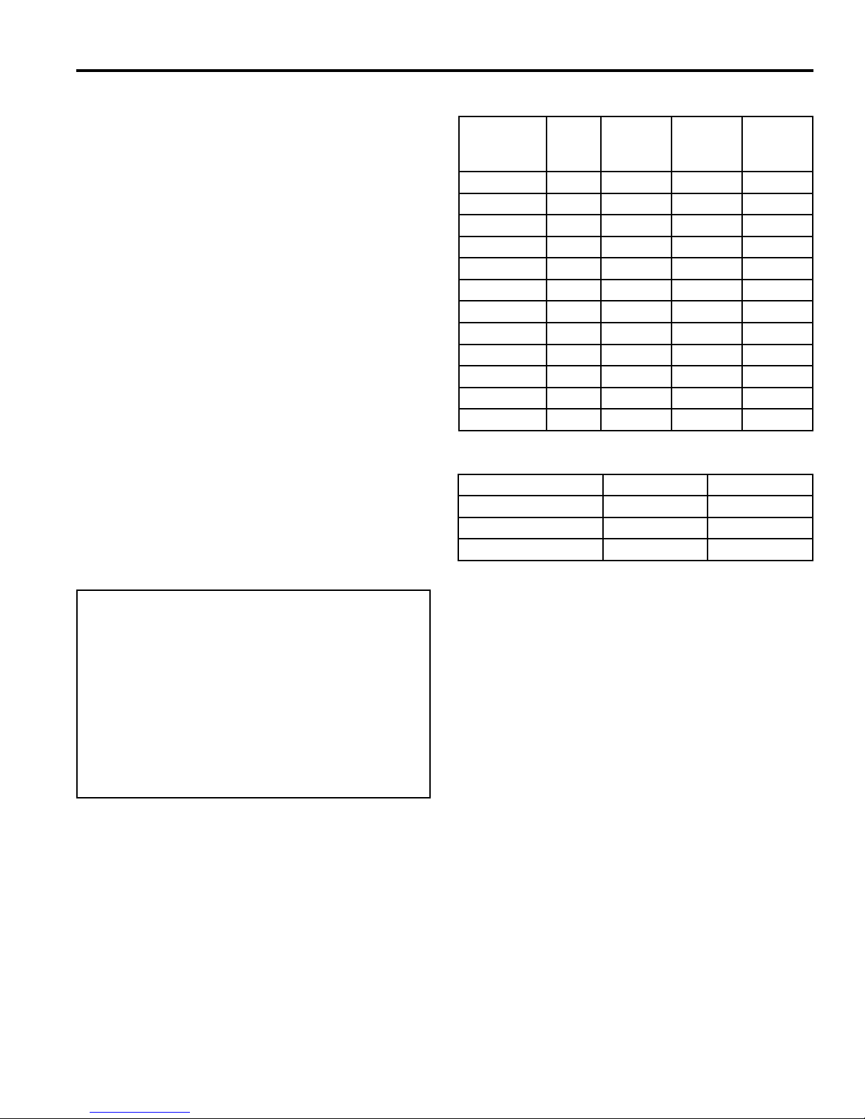
GAS SPECIFICATIONS & ORIFICE SIZE
MAX
INPUT
MODEL FUEL
33CFDVNV NAT. 18,000 12,300 #47
33CFDVPV LP 18,000 16,000 #55
33CFDVNI N AT. 18,000 12,300 #47
33CFDVPI LP 18,000 16,000 #55
36CFDVNV NAT. 21,000 15,000 #44
36CFDVPV LP 21,000 17,500 #54
36CFDVNI N AT. 21,000 15,000 #44
36CFDVPI LP 21,000 17,500 #54
42CFDVNV NAT. 24,000 16,500 2.35mm
42CFDVPV LP 24,000 17,500 1.45mm
42CFDVNI N AT. 24,000 16,500 2.35mm
42CFDVPI LP 24,000 17,500 1.45mm
BTU/H
MIN.
INPUT
BTU/H
ORIFICE
SIZE
GAS PRESSURES
Natural Gas Propane (LP)
Inlet Minimum 5.5" w.c. 11.0" w.c.
Inlet Maximum 14.0" w.c. 14.0" w.c.
Manifold Pressure 3.5" w.c. 10.0" w.c.
HIGH ELEVATIONS
Input ratings are shown in BTU per hour and are certied
without derating for elevations up to 4,500 feet (1,370
m) above sea level.
For elevations above 4,500 feet (1,370 m) in USA,
installations must be in accordance with the current
ANSI Z223.1/NFPA 54 and/or local codes having jurisdiction.
In Canada, please consult provincial and/or local authorities having jurisdiction for installations at elevations
above 4,500 feet (1,370 m).
COLD CLIMATE OPTION (IPI Models Only)
NOTE: If you live in a cold climate, seal all cracks around
your appliance and wherever cold air could enter the room,
with noncombustible material. It is especially important to
insulate the outside chase cavity between the studs and
under the oor on which the appliance rests, if the oor is
above ground level.
Your replace is equipped with an intermittent pilot ignition
(IPI) control. An IPI control with a standing pilot option pro-
vides the dual benet of an economical and environmentally
responsible product and one which lights easily even in
the coldest climates. When in intermittent pilot mode (as
it comes from the factory), your pilot remains unlit until
needed, saving you fuel. Standing pilot mode, by com-
parison, is characterized by a continuously burning pilot.
The benet of a pilot which lights only when needed is fuel
savings. However, with no pilot burning in your replace,
units operating in colder climates may experience delayed
start up or lock out. Because colder air is heavier than
milder air and there is no pilot burning to maintain a warm
stable temperature in your rebox, establishing a draft to
aid ignition becomes difcult. This is perfectly normal but
can be somewhat frustrating.
To remedy this issue, your replace has been designed with
a cold climate pilot option, which, when active, maintains
a warmer temperature inside your rebox to make ignition
20306739
5
CFDV Series Gas Fireplace
PRODUCT FEATURES
faster and more efcient. Operating your appliance in cold
climate (aka standing) pilot mode will prohibit the need for
multiple ignition attempts and will prevent the system from
delaying start up or locking out.
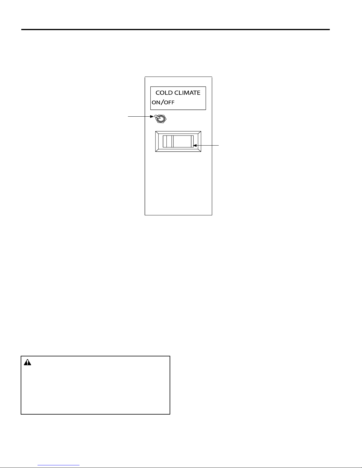
Cold Climate Switch
To activate the cold climate option, simply move the cold
climate toggle switch located on the right side of the black
control center to the “On” (left) position. (Figure 1) You can
operate your appliance in this mode regardless of whether
you are using a remote control, wall switch or thermostat.
Master Switch
Figure 1 –
CFDV Fireplace Controls–IPI (featuring Cold Climate option)
BATTERY BACK UP KIT INSTALLATION
The IPIBK battery back-up kit is intended for use with the
Ecologic IPI control system. The use of this battery back-
up kit will allow the replace to continue operating in the
event electric power is lost, such as may occur during
severe snow or ice storms.
Kit Contents:
• One (1) Battery holder with wires
• One (1) Installation instruction sheet
Not included:
• Four (4) AA alkaline batteries
WARNING
Turn off, unplug, and allow the replace to cool before installing the battery back-up kit. Only a qualied service person should service and repair the
replace. A qualied service person must connect
and disconnect the replace to the gas supply. Follow all local codes.
NOTE: To ensure you will always have back-up pow-
er available to your replace, replace batteries before
each heating season. Four (4) AA alkaline batteries are
required, (not included).
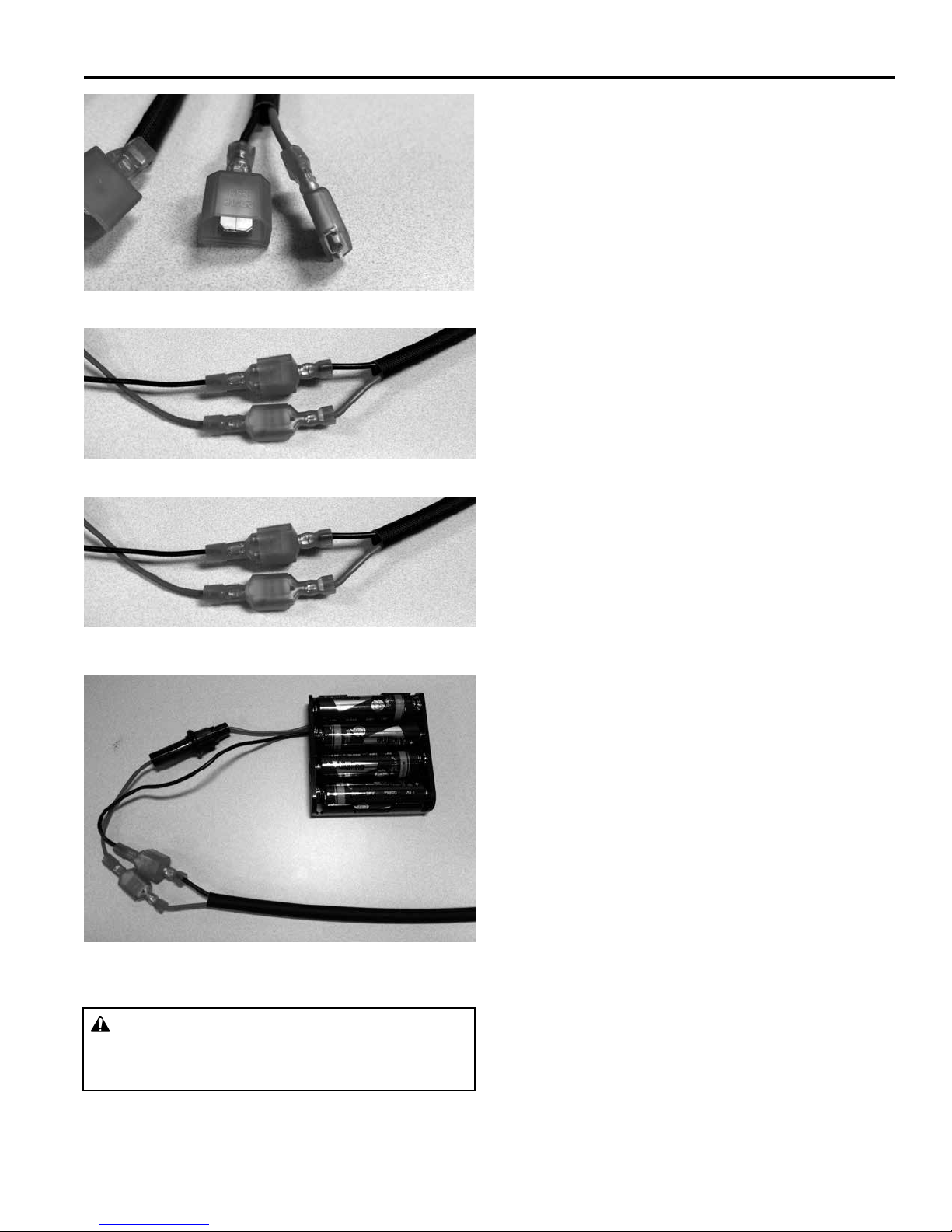
Installation Instructions
1. Find the appropriate male and female wire terminals
attached to the unused red and black colored wires
(Figure 2) on the wire harness located in the lower
control area of the replace.
2. Connect the female terminal of the red wire to the red
male terminal of the battery backup kit. Push termi-
nals together rmly. (Figure 3)
3. Connect the male terminal of the black wire to the
female black terminal of the battery backup kit. Push
terminals together rmly. (Figure 4)
4. Install four (4) fresh “AA” alkaline batteries into the
battery holder. Note correct polarity of each battery.
(Figure 5).
5. Place battery holder with batteries into the lower control area behind access panel with supplied Velcro.
6. Installation complete!
6
20306739
PRE-INSTALLATION INFORMATION
Figure 2 – Male/female wire terminals
Figure 3 – Female wire terminal connections
Figure 4 – Male wire terminal connections
CFDV Series Gas Fireplace
BEFORE YOU START
Read this homeowner manual thoroughly and follow all
instructions carefully. Inspect all contents for shipping
damage and immediately inform your dealer if any damage
is found. Do not install any unit with damaged, incomplete,
or substitute parts. Check your packing list to verify that
all listed parts have been received. You should have the
following:
• Fireplace (Firebox and Burner System)
• Log Set
• Rock Wool
• Volcanic Rock
• Battery Back-Up
• Restrictor Disks
ITEMS REQUIRED FOR INSTALLATION
Tools and Building Supplies:
• Phillips Screwdriver
• Hammer
• Pliers
• Square
• Level
• Tee Joint
• Pipe Wrench
• Saw and/or saber saw
• Measuring Tape
• Electric Drill and Bits
• Framing Materials
• Wall Finishing Materials
• Caulking Material (Noncombustible)
• Fireplace Surround Material (Noncombustible)
• Piping Complying with Local Codes
• Pipe Sealant Approved for use with Propane/LPG
(Resistant to Sulfur Compounds)
Figure 5 –Completed assembly
WARNING
Do not ll spaces around rebox with insulation or
other materials. This could cause a re.
20306739
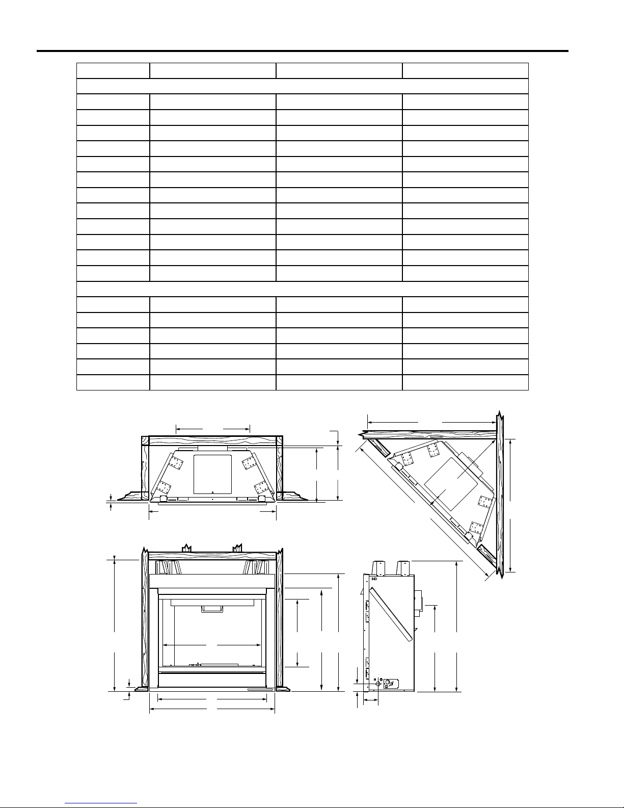
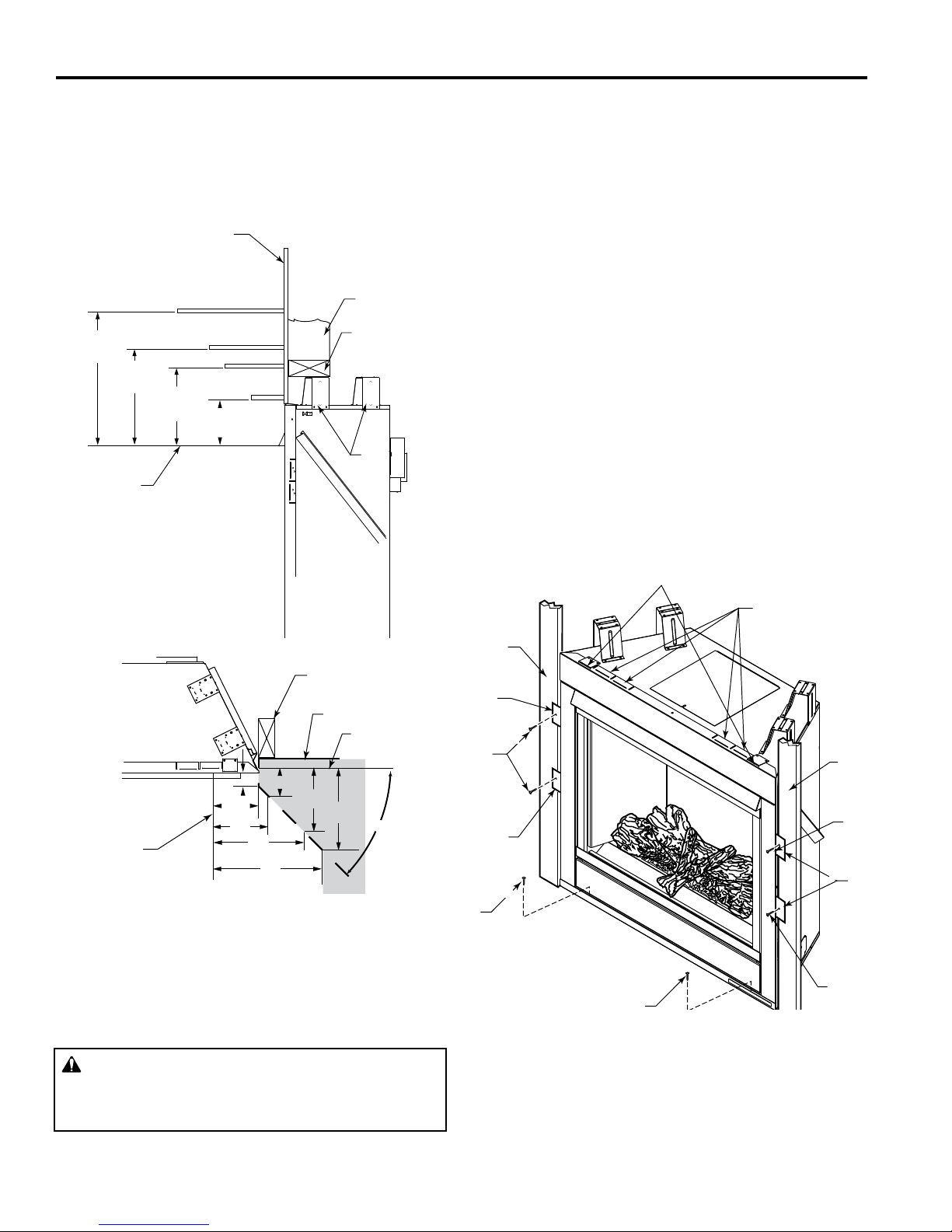
FIREPLACE FRAMING
Firebox framing can be built before or after the appliance
is set in place. Construct rebox framing following Figure
6 (page 8) for specic installation requirements and for
rebox dimensions. The framing headers may rest on the
top of the rebox standoffs. Do not bring headers below
top of standoffs.
The rebox may be installed directly on a combustible oor
or raised on a platform of an appropriate height. When
the rebox is installed directly on carpeting, tile, or other
combustible material, other than wood ooring, the rebox
shall be installed on a metal or wood panel extending the
full width and depth of the enclosure.
7
CFDV Series Gas Fireplace
REFERENCE 33CFDV 36CFDV 42CFDV
FIREPLACE DIMENSIONS
A 33" (838 mm) 37" (940 mm) 41" (1042 mm)
B 35
C 31
D 27" (689 mm) 29
E 18" (457 mm) 19
F 15
G 21
H 23
I 29
J 2
K 4
L 28
FRAMING DIMENSIONS
M 52
N 37" (940 mm) 38
O 27
P 15
Q 33
R 35
PRE-INSTALLATION INFORMATION
5
⁄8" (905 mm) 381⁄2" (978 mm) 381⁄2" (978 mm)
7
⁄8" (810 mm) 343⁄4" (883 mm) 343⁄4" (883 mm)
1
⁄8" (740 mm) 331⁄8" (841 mm)
7
⁄8" (505 mm) 197⁄8"(505 mm)
7
⁄8" (430 mm) 157⁄8" (430 mm) 157⁄8" (430 mm)
1
⁄8" (537 mm) 221⁄8" (562 mm) 261⁄2" (673 mm)
1
⁄4" (591 mm) 255⁄8" (657 mm) 255⁄8" (657 mm)
7
⁄8" (759 mm) 32" (813 mm) 36" (914 mm)
1
⁄4" (57 mm) 21⁄4" (57 mm) 21⁄4" (57 mm)
3
⁄8" (111 mm) 43⁄8" (111 mm) 43⁄8" (111 mm)
1
⁄8" (714 mm) 301⁄2" (775 mm) 301⁄2" (775 mm)
3
⁄8" (1330 mm) 541⁄2" (1384 mm) 575⁄8" (1464 mm)
1
⁄2" (978 mm) 403⁄4" (1035 mm)
1
⁄8" (689 mm) 28" (711 mm) 301⁄4" (768 mm)
5
⁄8" (397 mm) 155⁄8" (397 mm) 155⁄8" (397 mm)
1
⁄2" (850 mm) 371⁄2" (946 mm) 411⁄2" (1054 mm)
7
⁄8" (913 mm) 383⁄4" (978 mm) 383⁄4" (978 mm)
1/2" (13 mm)
or 5/8" (16 mm)
Minimum Rough
Opening
Height
15/16"
(24 mm)
G
Minimum Rough Opening Width
Q
D
I
A
Minimum Rough
Opening
Depth
F
P
CR E
L B
J
K
N
O
M
C
L
H
N
Figure 6 –
CFDV Series Fireplace Dimensions
8
20306739
CLEARANCES
CFDV Series Gas Fireplace
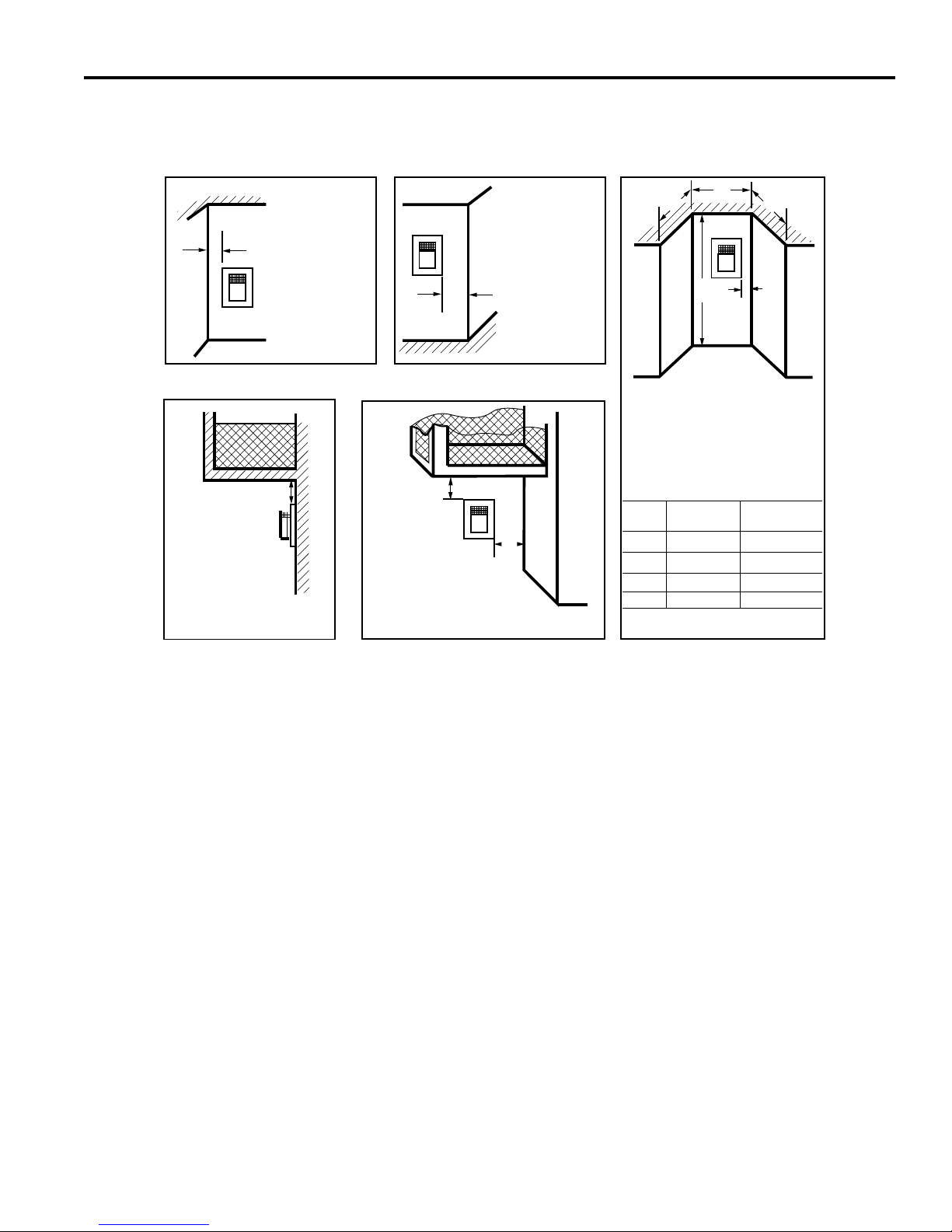
FIREPLACE LOCATION
Plan for the installation of your appliance. This includes
determining where the unit is to be installed, the vent con-
guration to be used, framing and nishing details, and
whether any optional accessories (i.e. blower, wall switch,
or remote control) are desired. Consult your local building
code agency to ensure compliance with local codes, including permits and inspections.
The following factors should be taken into consideration:
• Clearance to side-wall, ceiling, woodwork, and windows.
Minimum clearances to combustibles must be main-
tained.
• This replace may be installed along a wall, across a
corner, or use an exterior chase. Refer to Figure 4 for
suggested locations.
• Location should be out of high trafc areas and away
from furniture and draperies due to heat from appliance.
• Never obstruct the front opening of the replace.
• Do not install in the vicinity where gasoline or other
ammable liquids may be stored.
• Vent pipe routing. See Venting section found in this
manual for allowable venting congurations.
• These units can be installed in a bedroom. See National
Fuel Gas Code ANSI Z233.1/NFPA 54 — (current
edition), the Uniform Mechanical Code — (current edi-
tion), and Local Building Codes for specic installation
requirements.
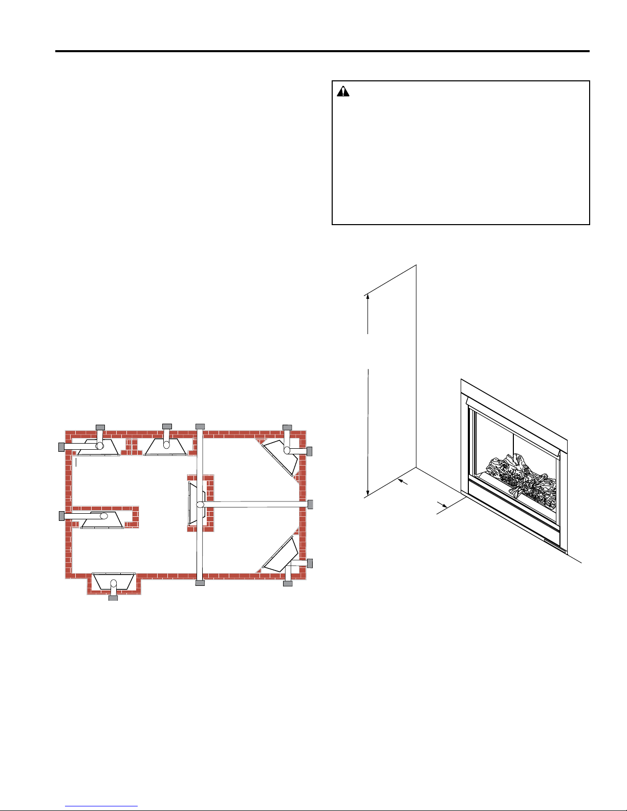
CLEARANCES TO COMBUSTIBLES
WARNING
Follow these instructions carefully to ensure safe
installation. Failure to follow instructions exactly
can create a re hazard.
The appliance cannot be installed on a carpet, tile
or other combustible material other than wood
ooring. If installed on carpet or vinyl ooring, the
appliance shall be installed on a metal, wood or
noncombustible material panel extending full width
and depth of the appliance.
Ceiling
72"
(1828 mm)
Minimum
Side Wall
E
Y
D
F
A Flat on Wall
B Cross Corner
C Island**
** Island (C) and room divider (D) installation is possible as long as the
horizontal portion of vent system (X) does not exceed 20' (6 m).
* When you install your replace in (D) room divider or (E) at on wall
corner positions (Y), a minimum of 6" (102 mm) clearance must be
maintained from perpendicular wall and front of replace.
Figure 7 –
Locating Gas Fireplace
A
C
D Room Divider*
E Flat on Wall Corner*
F Chase Installation
B
B
6"
(152 mm)
Minimum
Figure 8 –
Ceiling and Side Wall Clearances
FP3012
20306739
9
CFDV Series Gas Fireplace
FIREPLACE INSTALLATION
MANTEL CLEARANCES
NOTE: The combustible area above the facing must not
protrude more than 3/4" (19 mm) from the facing. If it
does, it is considered a mantel and must meet the mantel
requirements listed in this manual. Figure 9
Finish Wall
12”
(305 mm)
(279 mm)
Top of Heat
Exhaust Vent
Side View
11”
12” (305 mm)
10”
(254 mm)
8” (203 mm)
(152 mm)
6”
2¹⁄₂”
(64 mm)
8” (203 mm)
Stud
Header
Standoffs
FP3000
SECURE FIREPLACE TO FLOOR OR
FRAMING
The replace must be secured to the oor and/or to framing
studs as shown in Figure 10. Use two (2) wood screws or
masonry/concrete screws to secure replace to the oor.
Use four (4) screws to attach replace to framing. The side
nailing anges are 1⁄2" or 5⁄8" to accommodate different wall
thickness.
FINISHING MATERIAL
NOTE: Any wiring (i.e. remote control, wall switch, and
optional fan) must be done prior to nal nishing to avoid
costly reconstruction.
Only noncombustible materials (i.e. brick, tile, slate, steel,
or other materials with a UL re rating of Zero) may be
used to cover the black surface of the appliance. A 300°F
minimum adhesive may be used to attach facing materials
to the black surface. If joints between the nished wall
and the replace surround are sealed, a 300°F minimum
sealant material (General Electric RTV103 or equivalent)
must be used.
Finished Wall
Drywall Standoff
Support Tabs
(Do Not Use for
Framing or Header)
Stud
Wall
Combustible
Material Area
1"
1¹⁄₂”
6"
3¹⁄₂”
4¹⁄₂”
45°
FP3013
Side of Fireplace
Opening
2¹⁄₂”
3"
5"
Top View
Figure 9 –
Mantel Clearances
WARNING
Never obstruct or modify the air inlet. This may
create a re hazard.
Framing
Nailing
Flange
Screws
Nailing
Flange
Screw
Screw
Figure 10 –
Securing Fireplace to Floor and Framing Studs
Framing
Screw
Nailing
Flange
Screw
10
20306739

VENTING INSTALLATION
CFDV Series Gas Fireplace
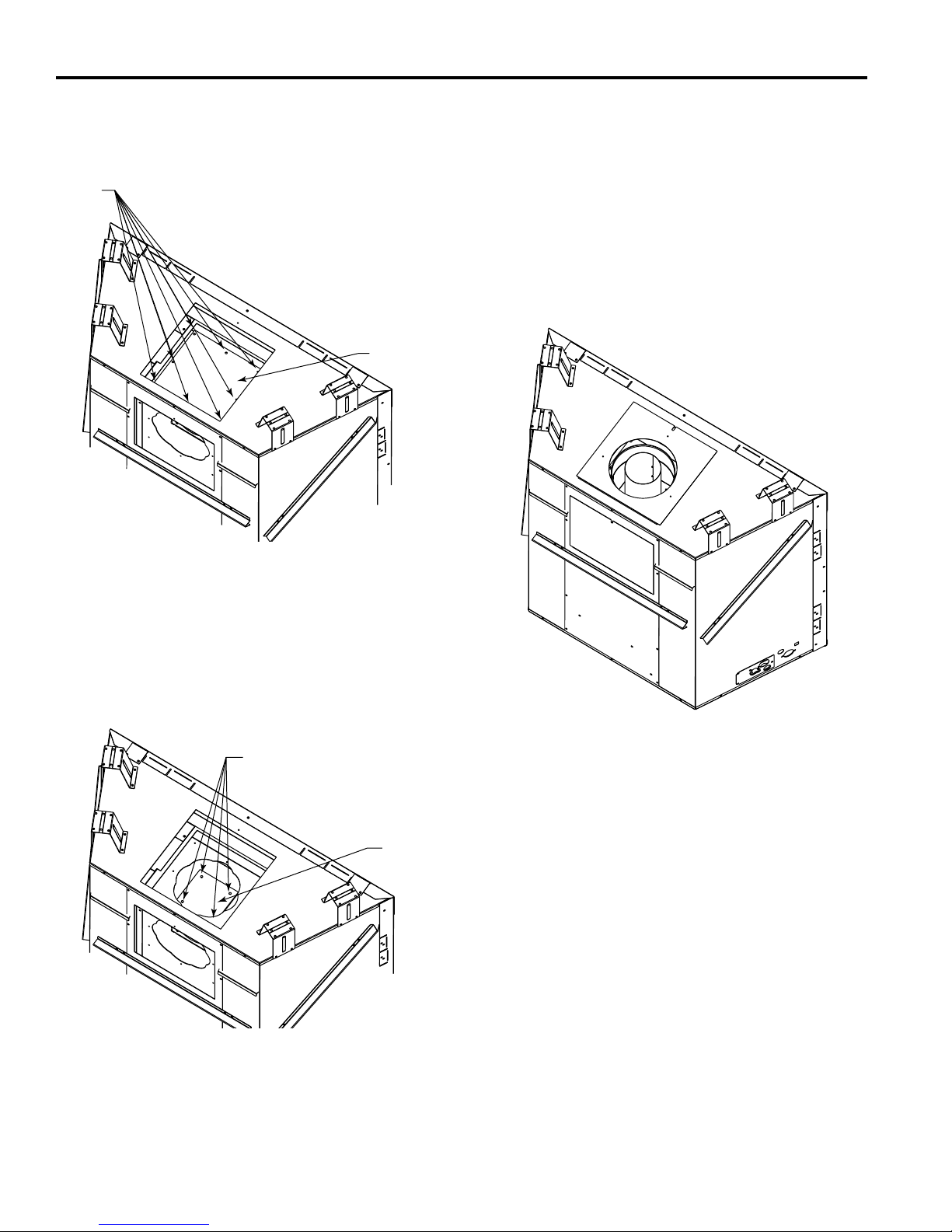
OPTIONAL TOP VENT APPLICATION
The appliance is shipped as a rear vent unit. If the installa-
tion layout requires the unit to be a top vent conguration
the appliance can be converted by following the steps
below.
When removing and retting the plates be sure the
associated gaskets are undamaged and retted as
required.
1. Remove the rear plate by removing one (1) screw. Set
aside. Figure 11
Screw
Rear Plate
3. Remove the plate with the 4" collar and gasket by removing four (4) screws. Set aside. Figure 13
4. Remove the top plate located on top of the unit by removing one (1) screw. Set aside. Figure 13
Top Plate
Remove
Screw
Remove
Screws
4" Collar
Remove
Screws
FP3023
FP3021
Figure 11 –
Remove Rear Plate
2. Remove the plate with the 7" collar and gasket by removing eight (8) screws. Set aside. Figure 12
Remove
Screws
7" Collar
Remove
Screws
FP3022
Figure 13 –
Remove 4" Collar and Gasket and Top Plate
5. Remove one (1) screw to remove the inner top plate
located on top directly beneath the plate just removed.
Break away the 7" circle using a screwdriver and reinstall. Figure 14
Inner Top Plate
FP3025
Remove Circle
Figure 12 –
Remove 7" Collar and Gasket
20306739
FP3024
Figure 14 –
Remove Circle Section from Inner Top Plate
11
CFDV Series Gas Fireplace
VENTING INSTALLATION
6. Remove the large square plate and gasket by removing
the eight (8) screws. Set aside. Figure 15
Remove
Screws
Large Square
Plate
FP3026
8. Install the plate with the 4" collar and gaskets on top of
the unit with screws previously removed.
9. Install the plate with the 7" collar and gaskets on top of
the unit with screws previously removed.
10. Install the small square plate and gaskets on the back
of the unit with screws previously removed, covering the
original rear opening for 4" collar.
11. Install the large square plate and gaskets on the back
of the unit with screws previously removed, covering
the original rear opening for 7" collar. Figure 17.
Figure 15 –
Remove Large Square Plate and Gasket
7. Remove the small square plate and gasket by removing
four (4) screws. Set aside. Figure 16
Remove Screws
Small
Square
Plate
FP3027
FP3028
Figure 17 –
Completed Top Vent Conversion
Figure 16 –
Remove Small Square Plate and Gasket
12
20306739
VENTING INSTALLATION
CFDV Series Gas Fireplace
WARNING
Read all instructions completely and thoroughly
before attempting installation. Failure to do so
could result in serious injury, property damage or
loss of life. Operation of improperly installed and
maintained venting system could result in serious
injury, property damage or loss of life.
WARNING
This replace must be vented to the outside.
The venting system must NEVER be attached
to a chimney serving a separate solid fuel
burning appliance. Each gas appliance must
use a separate vent system. Do not use common
vent systems.
WARNING
Do not pack the open air spaces with insulation or
other materials. This could cause high temperatures
and may present a re hazard.
NOTICE: Failure to follow these instructions will void the
warranty.
INSTALLATION PRECAUTIONS
Consult local building codes before beginning the
installation. The installer must make sure to select the
proper vent system for installation. Before installing vent
kit, the installer must read this replace manual and vent
kit instructions.
Only a qualied installer/service person should install venting system. The installer must follow these safety rules:
• Wear gloves and safety glasses for protection.
• Use extreme caution when using ladders or when on
rooftops.
• Be aware of electrical wiring locations in walls and
ceilings.
The following actions will void the warranty on your venting system:
GENERAL VENTING
Your replace is approved to be vented either through the
side wall, or vertical through the roof.
• Only Vermont Castings Group venting components
specically approved and labeled for this replace
may be used.
• Flexible UL1777 listed venting may be used in any vent-
ing application where rigid direct vent components can
be used. All restrictions, clearances and allowances that
pertain to the rigid piping apply to the exible venting.
Flex kits may not be modied. Flex kits may be added to
the end of a vent run made of rigid vent sections using
pipe manufacturer's approved ex to pipe adapters. This
may occur only if doing so does not violate any of the
venting length, height, routing, horizontal to vertical ratio
requirements or clearance considerations detailed in this
manual.
• Venting terminals shall not be recessed into a wall or sid-
ing.
• Vertical side wall venting in horizontal applications must
be installed with a 1/4" rise for every 12" of run.
• Select the amount of vertical rise desired. All horizontal
run of venting must be run level or have 1/4" rise for every
12" (305 mm) of run towards the termination below 71⁄2
feet of vertical rise. With 71⁄2 feet (2.3 m) or more vertical
rise from oor of replace, the horizontal run may run level. NEVER run vent piping downward.
• Horizontal venting which incorporates the use of ex
venting shall have an inclining slope from the unit of 1/2"
(13 mm) per 12" (305 mm).
There must not be any obstruction such as bushes, garden sheds, fences, decks or utility buildings within 24"
(610 mm) from the front of the termination hood.
Do not locate termination hood where excessive snow or
ice build up may occur. Be sure to check vent termination area after snow falls, and clear to prevent accidental
blockage of venting system. When using snow blowers,
make sure snow is not directed towards vent termination
area.
Location of Vent Termination
It is imperative the vent termination be located observing
the minimum clearances as shown on following page.
• Installation of any damaged venting component.
• Unauthorized modication of the venting system.
• Installation of any component part not manufactured
or approved by Vermont Castings Group.
• Installation other than permitted by these instructions.
20306739
13
CFDV Series Gas Fireplace
V
X
X
X
D
E
B
B
B
C
B
M
B
A
J
K
F
L
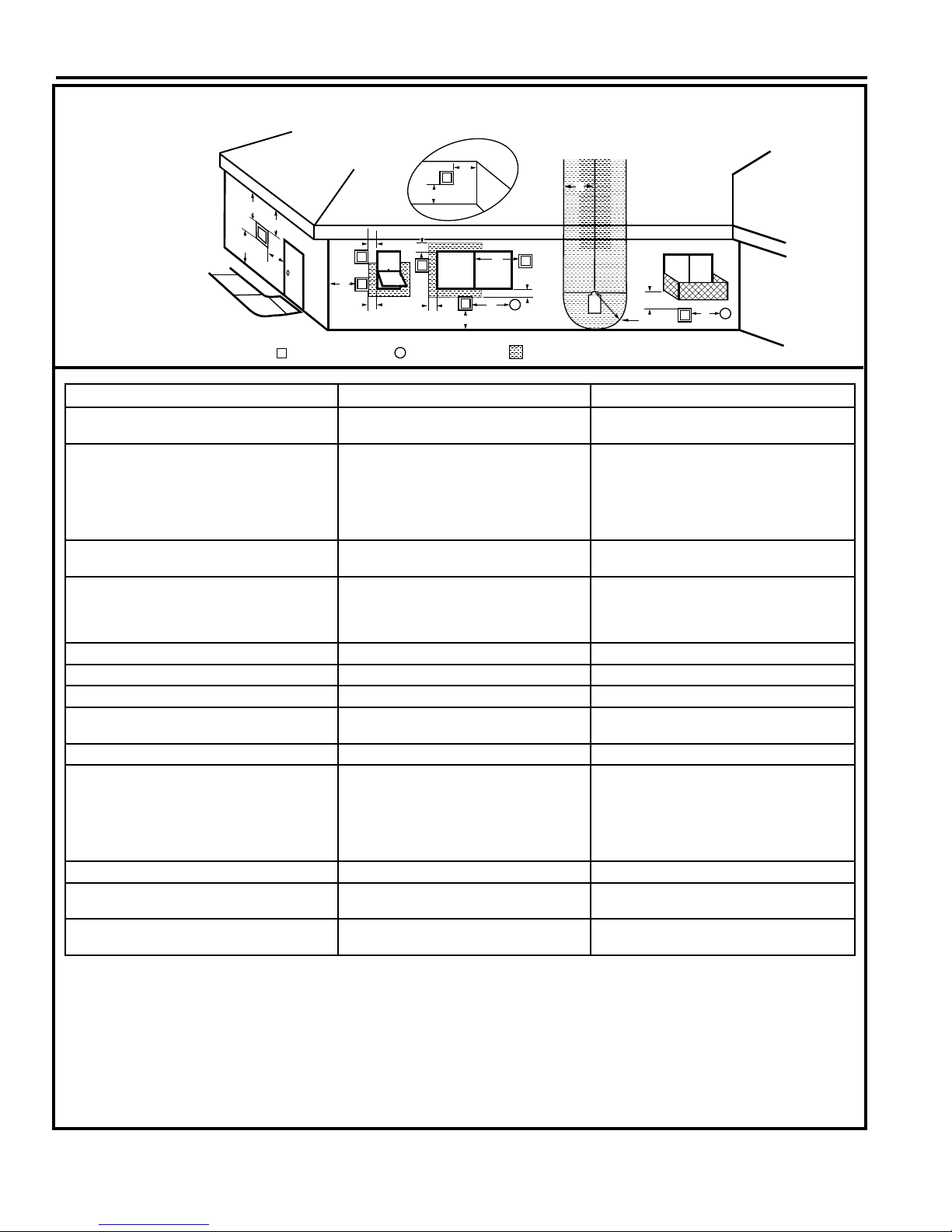
VENT TERMINATION AIR SUPPLY INLET
AREA WHERE TERMINAL IS NOT PERMITTED
H
I
Fixed
Closed
Operable
Operable
Fixed
Closed
B
INSIDE
CORNER DETAIL
A
G
CFM145a
V
V
V
V
V
V
V
V
TERMINATION LOCATION
Figure 18 –
Termination Locations
VENTING INSTALLATION
A = Clearance above grade, veranda, porch,
CANADIAN INSTALLATIONS
1
12" (30cm) 12" (30cm)
US INSTALLATIONS
2
deck or balcony
B = Clearance to window or door that may be
opened
C = Clearance to permanently closed window 12" (305mm) recommended to prevent
D = Vertical clearance to ventilated soft
6" (15cm) for appliances <10,000 BTU/h
(3kW)
12" (30cm) for appliances >10,000 BTU/h
(3kW) and <100,000 BTU/h (30kW)
36" (91cm) for appliances >100,000 BTU/h
(30kW)
6" (15cm) for appliances <10,000 BTU/h
(3kW)
9" (23cm) for appliances >10,000 BTU/h
(3kW) and <50,000 BTU/h (15kW)
12" (30cm) for appliances >50,000 BTU/h
(15kW)
12" (305mm) recommended to prevent
window condensation
window condensation
18" (458mm) 18" (458mm)
located above the terminal within a hor-
izontal distance of 2' (610 mm) from the
center line of the terminal
E = Clearance to unventilated soft 12" (305mm) 12" (305mm)
F = Clearance to outside corner see next page see next page
G = Clearance to inside corner see next page see next page
H = Clearance to each inside of center line
extended above meter/regulator assembly
3' (91cm) within a height of 15' (5m) above
the meter/regulator assembly
3' (91cm) within a height of 15' (5m) above
the meter/regulator assembly
I = Clearance to service regulator vent outlet 3' (91cm) 3' (91cm)
J = Clearance to non-mechanical air supply
inlet to building or the combustion air inlet
to any other appliance
6" (15cm) for appliances <10,000 BTU/h
(3kW)
12" (30cm) for appliances >10,000 BTU/h
(3kW) and <100,000 BTU/h (30kW)
36" (91cm) for appliances >100,000 BTU/h
(30kW)
6" (15cm) for appliances <10,000 BTU/h
(3kW)
9" (23cm) for appliances >10,000 BTU/h
(3kW) and <50,000 BTU/h (15kW)
12" (30cm) for appliances >50,000 BTU/h
(15kW)
K = Clearance to mechanical air supply inlet 6' (1.83m) 3' (91cm) above if within 10' (3m) horizontally
L = Clearance above paved sidewalk or
7' (2.13m)
†
7' (2.13m)
†
paved driveway located on public property
M = Clearance under veranda, porch, deck or
12" (30cm)
‡
12" (30cm)
‡
balcony
1 In accordance with the current CSA-B149 Installation Codes
2 In accordance with the current ANSI Z223.1/NFPA 54 National Fuel
Gas Codes
† A vent shall not terminate directly above a sidewalk or paved
driveway which is located between two single family dwellings and
serves both dwellings
‡ Only permitted if veranda, porch, deck or balcony is fully open on a
minimum 2 sides beneath the oor.
14
NOTE: 1. Local codes or regulations may require different
2. The special venting system used on Direct Vent
3. Vermont Castings Group assumes no responsibility for
clearances.
Fireplaces are certied as part of the appliance, with
clearances tested and approved by the listing agency.
the improper performance of the appliance when the venting
system does not meet these requirements.
20306739
VENTING INSTALLATION
TERMINATION CLEARANCES
Termination clearances for buildings with combustible and non-combustible exteriors.
CFDV Series Gas Fireplace
Inside Corner
G =
G
Balcony -
with no side wall
Combustible
6" (152 mm)
Noncombustible
V
2" (51 mm)
M
V
M =
Combustible &
Noncombustible
12" (305 mm)
*NOTE: Termination in an alcove space (spaces open only on one side
and with an overhang) is permitted with the dimensions specied for
vinyl or non-vinyl siding and softs. 1. There must be a 3' (914 mm) minimum between termination caps. 2. All mechanical air intakes within 10'
Outside Corner
V
F
Balcony -
with perpendicular side wall
M
Combustible &
Noncombustible
M = 12" (305 mm)
P = 6” (152 mm)
Figure 19 –
Termination Clearances
Alcove Applications*
D
F =
Combustible
6" (152 mm)
Noncombustible
2" (51 mm)
C
O
C
V
E
E = Min. 2” (51 mm) for
non-vinyl sidewalls
Min. 12” (305 mm) for
vinyl sidewalls
O = 8’ (2.4 m) Min.
No. of
V
P
(1 m) of a termination cap must be a minimum of 3' (914 mm) below the
termination cap. 3. All gravity air intakes within 3' (914 mm) of a termination cap must be a minimum of 1' (305 mm) below the termination cap.
Caps Dmin. Cmax.
1 3' (914 mm) 2 x Dactual
2 6' (1.8 m) 1 x Dactual
3 9' (2.7 m) 2/3 x Dactual
4 12' (3.7 m) 1/2 x Dactual
DMin. = Number of Termination caps x 3
CMax. = (2 / Number termination caps) x DActual
584-15
ASSEMBLING VENT PIPE
Only venting components manufactured or approved by
Vermont Castings Group may be used in Direct Vent systems.
USA Installations
The venting system must conform to local codes and/or
the current National Fuel Code ANSI Z223.1/NFPA 54.
Canadian Installations
The venting system must be installed in accordance with
the current CSA-B149.1 installation code.
20306739
15
CFDV Series Gas Fireplace
VENTING INSTALLATION
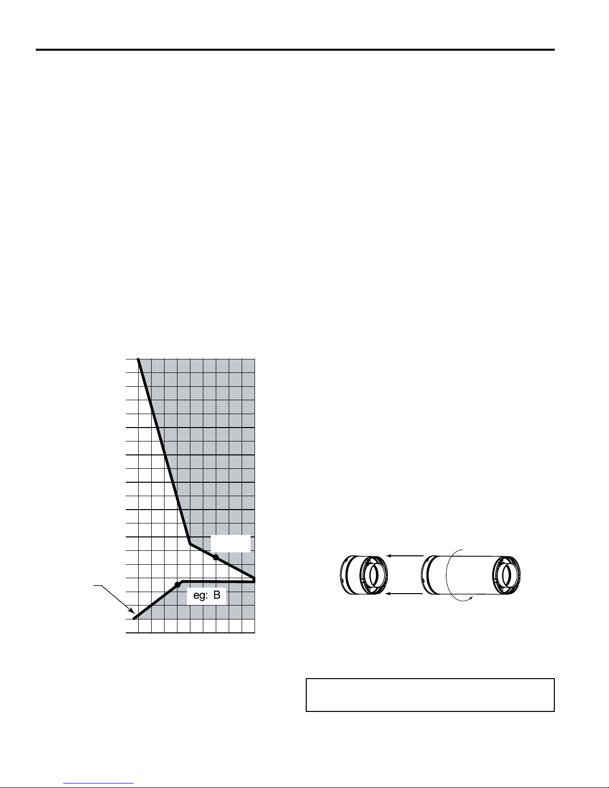
HOW TO USE THE VENT GRAPH
The Vent Graph should be read in conjunction with the
following vent installation instructions to determine the re-
lationship between the vertical and horizontal dimensions
of the vent system.
1. Determine the height of the center of the horizontal
vent pipe exiting through the outer wall. Using this
dimension on the Side wall Vent Graph, Figure 20, locate the point intersecting with the slanted graph line.
2. From the point of this intersection, draw a vertical line
to the bottom of the graph.
3. Select the indicated dimension, and position the replace in accordance with same.
EXAMPLE A:
If the vertical dimension from the oor of the unit is 11' (3.4
m) the horizontal run to the face of the outer wall must not
exceed 14' (4.3 m).
EXAMPLE B:
If the vertical dimension from the oor of the unit is 7' (2.1
m), the horizontal run to the face of the outer wall must not
exceed 8' (2.4 m).
Refer to Page 26 for snorkel requirements.
40
38
36
34
32
30
28
26
24
22
20
18
X
16
14
12
10
8
6
4
2
eg: A
the Horizontal Vent Pipe
Vertical Dimension from the Floor of Unit to the Center of
SLP PIPE
When using SLP pipe it is not necessary to use sealant
on the joints.
To join SLP pipe together, simply align the beads of the
male end with the grooves of the female end, twisting the
pipe until the ange on the female end contacts external
ange on the male end. NOTE: Sealant is not required to
assemble replace venting. Do not use silicone sealant at
the inner ue exhaust connections.
1. Attach the First Vent Component to SLP Starting
Collars
To attach the rst vent component to the starting collars of the appliance:
• Lock the vent components into place by sliding the
pipe section onto the collar.
• Align the seam of the pipe and seam of collar to allow
engagement. Rotate the vent component to lock into
place. Use this procedure for all vent components.
See Figure 21.
• Continue adding vent components, locking each
succeeding component into place.
• Ensure that each succeeding vent component
is securely tted and locked into the preceding
component.
2. Commercial or High-Rise Applications
For installation into a commercial or high-rise application: All outer pipe joints must be sealed with high
temperature aluminum foil tape, including the slip sec-
tion that connects directly to the horizontal termination
cap.
• Only outer pipes are to be sealed. Do not seal the
inner ue. All unit collar, pipe, slip section, elbow
and cap outer ues shall be sealed in this manner,
unless otherwise stated.
2 - Rotate
1 - Align Seams
Horizontal Dimension From the Outside of Termination to
2 4 6 8 10 12 14 16 18 20
the Back of the Fireplace
X = 22" minimum for 33" Model
X = 251⁄4" minimum for 36" and 42" Models
(Floor to center of horizontal pipe)
Figure 20 –
Side Wall Venting Graph
16
Figure 21–
Adding Venting Components
Note: The end of the pipe sections with the lances/tabs
on it will face toward the appliance.
20306739
VENTING INSTALLATION
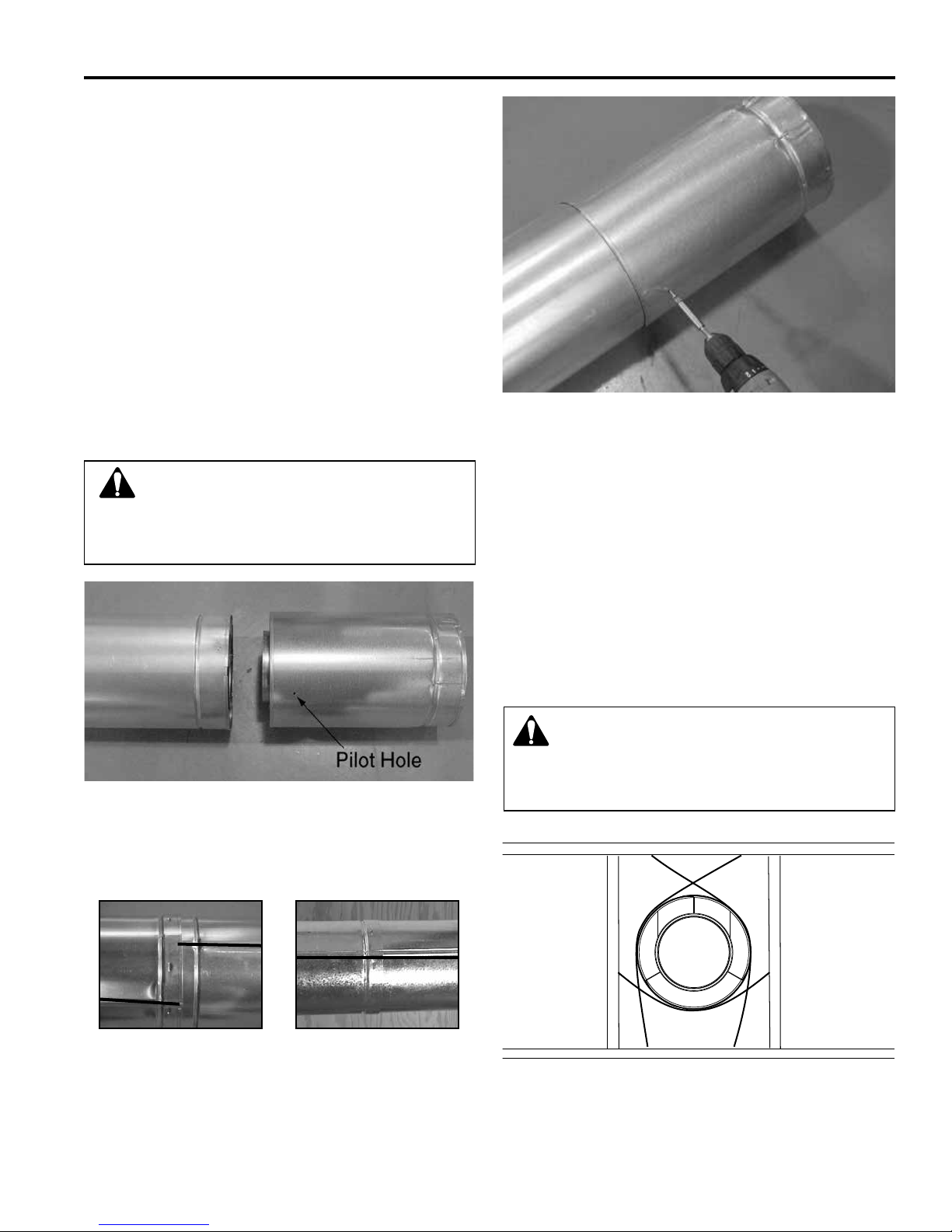
ADDITIONAL ASSEMBLY INSTRUCTIONS
1. Assemble Slip Sections
The outer ue of the slip section should slide over the
outer ue of the pipe section and into the inner ue of
the last pipe section (see Figure 22A).
Slide together to the desired length, making sure that
a 11⁄2 in. outer ue overlap is maintained between the
pipe section and slip section.
The pipe and slip section need to be secured by driving two 1⁄2 in. screws through the overlapping portions
of the outer ues using the pilot holes (see Figure 23).
This will secure the slip section to the desired length
and prevent it from separating. The slip section can
then be attached to the next pipe section.
If the slip section is too long, the inner and outer ues
of the slip section can be cut to the desired length.
CFDV Series Gas Fireplace
Figure 23–
Screws into Slip Section
WARNING! Risk of Fire/Explosion! DO NOT
break seals on slip sections. Use care when removing termination cap from slip pipe. If slip section
seals are broken during removal of the termination
cap, vent may leak.
Figure 22A–
Slip section pilot holes
Make sure the seams are not aligned to prevent unintentional
disconnection.
(see Figure 22B)
2. Secure the Vent Sections
Vertical sections of SLP pipe must be supported every
8 ft.
The SLP restop includes tabs that may be used to
secure vertical sections.
The vent support or plumber’s strap (spaced 120°
apart) may be used to secure the vertical sections of
pipe (see Figure 24).
Horizontal sections of vent must be supported every
5 ft with a vent support or plumber’s strap (see Figure
8).
WARNING! Risk of Fire/Explosion/Asphyxiation!
Improper support may allow vent to sag and
separate. Use vent run supports and connect vent
sections per installation instructions. DO NOT allow
vent to sag below connection point to appliance.
CORRECT INCORRECT
Figure 22B–
Seams
20306739
Figure 24–
Securing Vertical Pipe Sections
17
CFDV Series Gas Fireplace
Figure 25 –
Securing Horizontal Pipe Sections
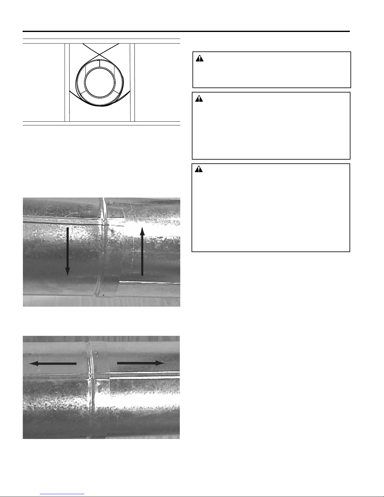
DISASSEMBLE VENT SECTIONS
To disassemble any two pieces of pipe, rotate either
section (Figure 26), so that the seams on both pipe sections are aligned (Figure 27). They can then be carefully
pulled apart.
HOW TO USE THE VENT GRAPH
VENT PIPE CLEARANCES
WARNING
All vertical sections of this vent system require a
minimum of 1" (25 mm) clearance to combustibles
on all sides of the pipe.
WARNING
Rear Wall Vent: Horizontal sections of this vent
system require a minimum of 3" (76 mm) clearances
to combustibles at the top of the ue and 1" (25
mm) clearance at the sides and bottom until the
flue penetrates the outside wall. A minimum 1"
clearance all around the ue is acceptable at this
point of penetration.
WARNING
Rear/Top Vent Vertical Side wall: Horizontal sections
of this vent system require a minimum of 3" (76 mm)
clearances to combustibles at the top of the ue and
1" (25 mm) clearance at the sides and bottom until
the ue penetrates the outside wall. A minimum 1"
clearance all around the ue is acceptable at this
point of penetration. (If vertical rise is 71/2 feet (2.3
m) or higher from the oor when top venting, the
clearance to combustibles is 1" on all sides of the
horizontal run.)
Figure 26 –
Rotate Seams for Disassembly
Figure 27–
Align and Disassemble Vent Sections
18
20306739
VENTING INSTALLATION
CFDV Series Gas Fireplace
A Minimum of 3" (76 mm)
Clearance to the Top Is
Required Along Horizontal
Length until Flue Pipe
Penetrates Outside Wall.
Rear Vent
A Minimum 1" (25
mm) Clearance to
Combustibles Permitted
All Around Flue
at Outside Wall
1"
3"
1"
1"
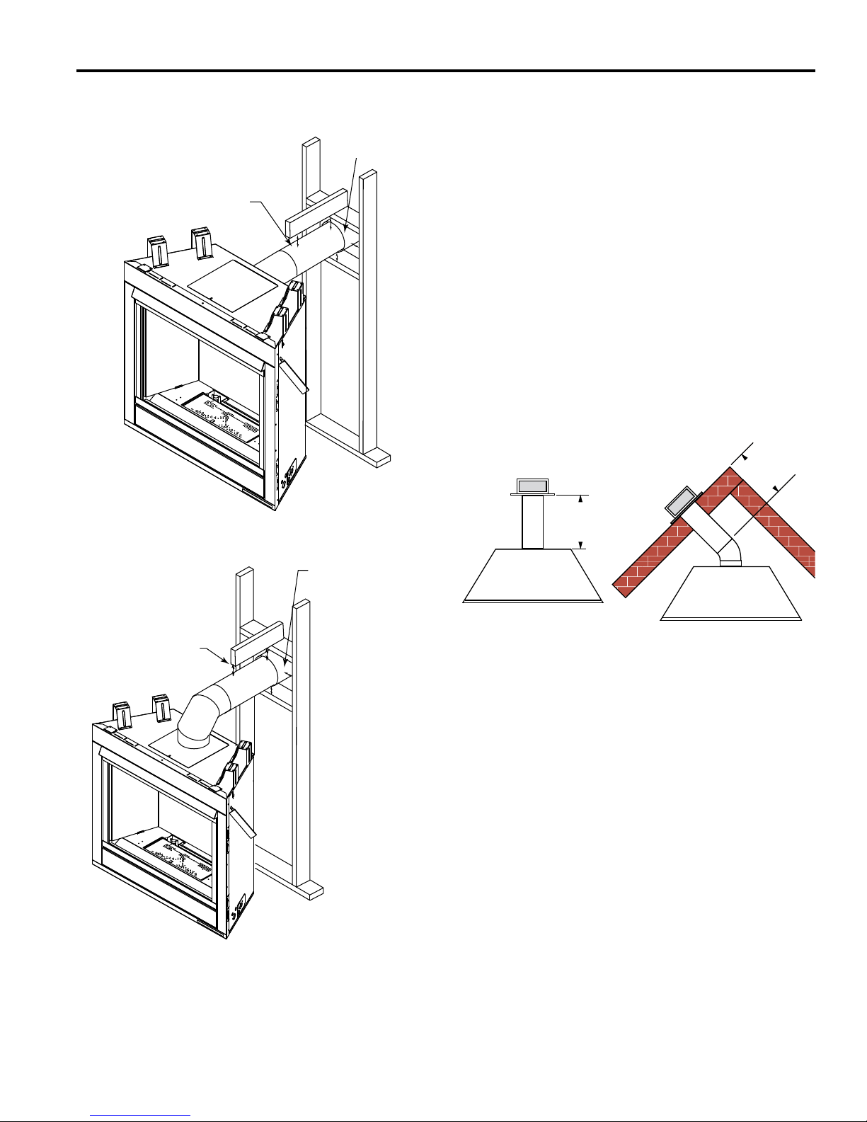
REAR WALL VENT APPLICATIONS
When installed as a rear vent unit this appliance may be
vented directly to a termination located on the rear wall
behind the appliance.
• Only Vermont Castings Group approved venting com-
ponents are approved to be used in these applications
(Refer to ‘Venting Components’ listed for different installation requirements).
• The maximum horizontal distance between the rear of
the appliance (or end of the 45º elbow in a corner application) and the outside face of the rear wall is 20"
(508 mm). Figure 23
• Only one 45° elbow is allowed in these installations.
• Minimum clearances between vent pipe and combus-
tible materials are as follows:
Top – 3" (76 mm), except at outside wall 1" (25 mm)
Sides – 1" (25 mm)
Bottom – 1" (25 mm)
Rear Vent Top View
20”
(508 mm)
Max.
A Minimum of 3" (76
mm) Clearance to the
Top Is Required Along
Horizontal Length until
Flue Pipe Penetrates
Outside Wall.
Top Vent
Figure 28 –
Combustible Clearances for Vent Pipe
3"
1"
1"
1"
A Minimum 1" (25
mm) Clearance
to Combustibles
Permitted All Around
Flue at Outside Wall
20”
(508 mm)
Max.
Figure 29 –
Rear Vent Application, No Elbows
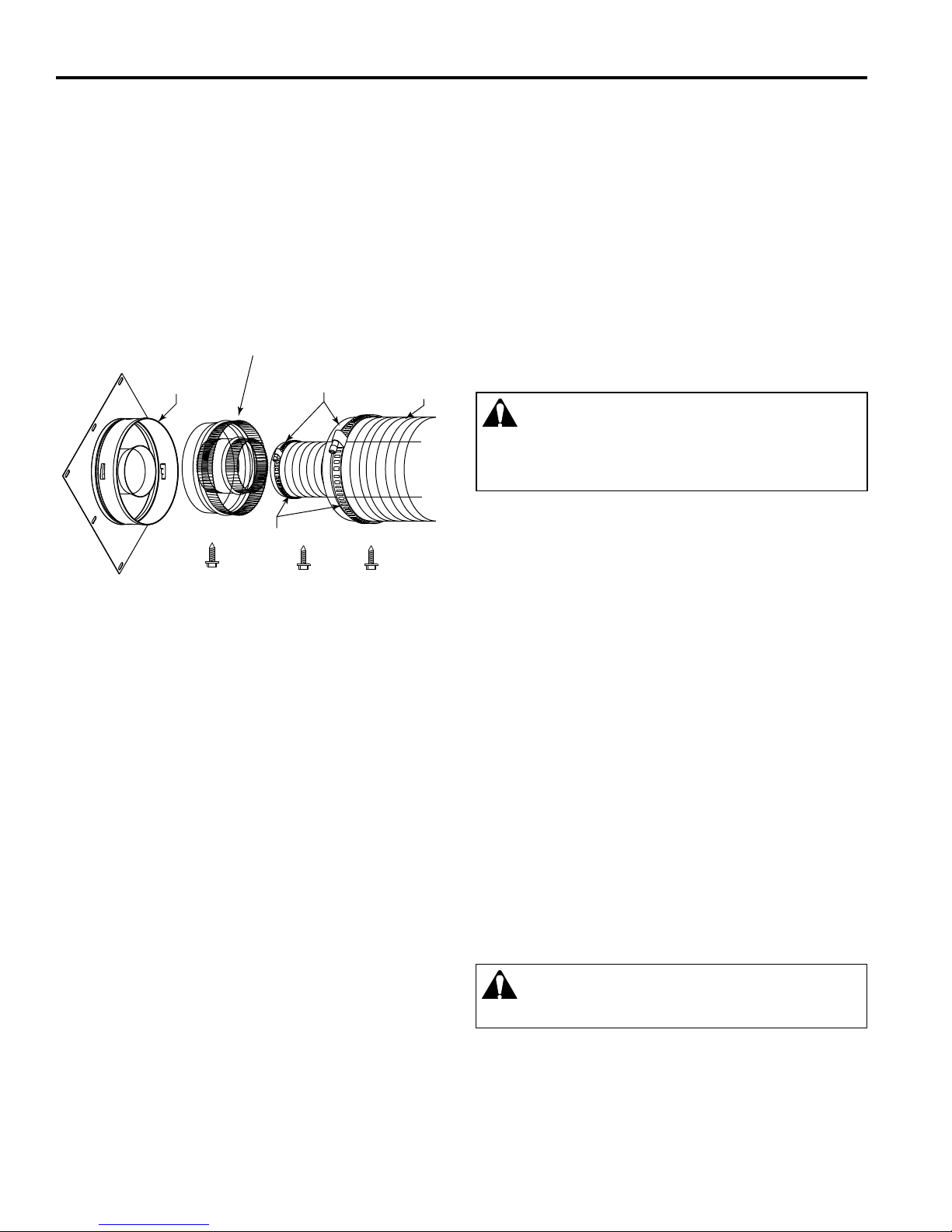
INNER FLEX VENT PIPE
Start the exible vent as follows—
A. Installing the inner ex adaptor and pipe.
1. Attach the ex adapter starter onto the starting col-
lar on the unit. Align seam of the pipe and seam of
collar to allow engagement. Rotate the ex starter
to lock onto appliance. Install three (3) self tapping
#10 screws through the ex starter into the starting
collar of the appliance.
2. Slide the small gear clamp over the inner exible
vent pipe, and push out of the way.
3. Pull and extend the inner exible vent.
4. Slide the inner vent onto the adapter collar, for a
minimum 2" overlap.
5. Locate the clamp at approximately 3/4" from the
ex end and tighten.
6. Secure the clamped inner section with three self
tapping screws, drilled equidistant, just above the
clamp perimeter.
20306739
FP3018
19
CFDV Series Gas Fireplace
VENTING INSTALLATION
B. Installing the outer ex pipe. Figure 30
1. Slide the large gear clamp over the outer exible
vent pipe, and push out of the way.
2. Pull and extend the outer exible vent.
3. Slide the outer vent onto the appliance collar
outer adapter for a minimum 2" overlap.
4. Locate the clamp at approximately 3/4" from
the ex end and tighten.
5. Secure the clamped outer section with three
self tapping screws, drilled equidistant, just
above the clamp perimeter.
Flex Adapter
Appliance
Starting Collar
Starter
Gear Clamps
2" Flexible
Pipe and
Adapter Outer
Collar Overlap
UL 1777
Flex Vent
ing with trim or “J channel” and caulking to prevent water from leaking into the building. Figure 13
4. Attach the termination cap to the exterior wall using
four (4) screws provided.
5. Guide the venting throught the vent hole as you place
the appliance in its installed position. Guide the 4" (102
mms) and 6
5
⁄8" (168mm) collar of the vent termination
into the outer ends of the venting. Do not force the
termination. If the vent pieces do not align with the termination, remove and realign the venting at the appliance ue collars. Figure 31 Attach the termination to
the wall as outlined in the instruction sheet supplied
with the termination.
HORIZONTAL TERMINATION CAP
WARNING! Risk of Fire! The telescoping ue sec-
tion of the termination cap MUST be used when
connecting vent. 11⁄2 (38 mm) minimum overlap of vent
and telescoping ue section is required. Failure to
maintain overlap may cause overheating and re.
NOTE: For horizontal vent runs through a combustible
wall and framing dimensions, refer to appliance installation
manual.
Figure 0 –
Typical Appliance Connection
SLP-RVTM -
HORIZONTAL TERMINATION KIT
Installation Instructions
1. A wall square restop MUST BE installed if the vent
passes through a ceiling or exterior wall. Cut a 9” wide
x 9” high (229 x 229 mm) opening through the exterior
wall or framing. A wall rectangular restop (not provided) MUST BE installed if the vent passes through interior walls. In that case, cut a 10” wide x 10” high (254
x 254 mm) opening through the wall or framing. The
framing members may need to be reinforced. Position
the restop on the hole previously cut and secure with
screws or nails (not provided). Run vent pipe through
restop. The gap between the vent pipe and restop
may be sealed.
2. Attach slip section of cap to last vent section. Maintain 1-1/2 in. overlap between slip and vent sections.
Make sure the termination cap is installed with the embossed arrow pointing up.
3. If the house has vinyl siding, mark and cut the vinyl
siding around the pipe so the termination cap can be
mounted ush to the wall. Finish the edges of the sid-
Installation Instructions
1. Attach slip section of cap to last vent section. Maintain 11⁄2 in. overlap between slip and vent sections.
NOTE: For installations using black pipe, slide the
decorative wall thimble over the last vent pipe before
connecting the termination to the pipe. When this
connection has been made, slide the wall thimble up to
the interior wall surface and attach with screws provided.
1. Secure termination cap to exterior wall using provided holes and fasteners.
2. Vent termination must not be recessed in the wall.
Siding may be brought to the edge of the cap base.
3. Flash and seal as appropriate for siding material at
outside edges of cap.
When installing a horizontal termination cap, follow the cap
location guidelines as prescribed by current ANSI Z223.1
and CAN/CGA-B149 installation codes.
CAUTION! Risk of Burns! Local codes may require installation of a termination guard to prevent
anything or anyone from touching the hot cap.
20
20306739
VENTING INSTALLATION
CFDV Series Gas Fireplace
Finish Wall
Firestop
Figure 31 –
Side View of Final Unit Location
Vent
Termination
FP2294
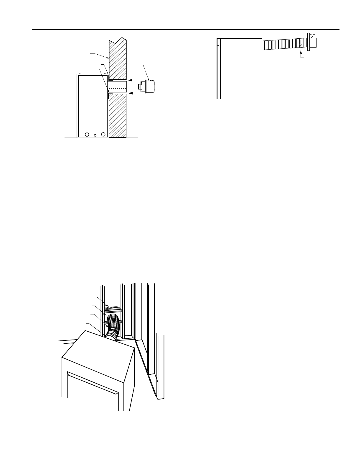
REAR WALL VENT INSTALLATIONS –
FLEX VENT PIPE
Follow Steps 1 and 2 on Page 20.
Step 3
Install the 4" (102 mm) ex vent pipe to the appliance collars described in the General Information Assembling Vent
Pipes section of this manual. If the installation requires a
45° angle, grasp the vent pipe close to the appliance collar
and bend to 45°. DO NOT exceed 45°. Figure 32
Install the 7" vent pipe in the same manner as Step 2.
NOTE: There must be a 1⁄2" (13 mm) rise in a 12" (305
mm) length of ex vent. Figure 33
Step 4
Assemble the ex vent to the collars on the termination as
you did on the appliance.
Termination
Firestop
Flex section
Appliance collars
FP1473
Figure 32 –
Grasp the vent pipe close to the collar and end to 45°
angle. Do not exceed 45°.
Rise
FP1472
Figure 33 –
There must be a 1/2" rise per foot length
TOP VENT SIDE WALL APPLICATION
Since it is very important that the venting system
maintain its balance between the combustion air intake and the ue gas exhaust, certain limitations as
to vent congurations apply and must be strictly adhered to.
The Vent Graph, showing the relationship between verti-
cal and horizontal side wall venting, will help to determine
the various dimensions allowable.
Minimum clearance between vent pipes and combustible materials is 3" (76 mm) on top, and 1" (25 mm) on
the bottom and sides unless otherwise noted.
When vent termination exits through foundations less
than 20" (508 mm) below siding outcrop, the vent pipe
must ush up with the siding.
It is best to locate the replace in such a way that minimizes the number of offsets and horizontal vent length.
The horizontal vent run refers to the total length of vent
pipe from the ue collar of the replace (or the top of the
Transition Elbow) to the face of the outer wall.
Horizontal plane means no vertical rise exists on this portion of the vent assembly.
When installing the appliance as a rear vent unit, the
90° or 45° Transition Elbow attached directly to the
rear of the unit is NOT INCLUDED in the following cri-
teria and calculations, and unless specically mentioned should be ignored when calculating venting
layouts.
• The maximum number of 90° elbows per side wall in-
stallation is three (3). Figure 34
• If a 90° elbow is tted directly on top of the replace
ange the maximum horizontal vent run before the ter-
mination or a vertical rise is 36" (914 mm). Figure 35
• If a 90° elbow is used in the horizontal vent run (lev-
el height maintained) the horizontal vent length is re-
duced by 36" (914 mm). Figures 36 & 37. This does
not apply if the 90° elbows are used to increase or
redirect a vertical rise. Figure 34
20306739
21
 Loading...