

Vermont Castings 20011992, 20012367, 20012368, 20013200, 20013199 Installation Instructions Manual
...
Burner Orifice (3 or 4)
(Refer to Table 1 or 3
to Confirm Sizes)
Pilot Orifice
Fuel Conversion Kit
Installation Instructions
Kits:
Natural to LP:
20011992, 20012367, 20012368
LP to Natural:
20013200, 20013199, 20013196
for Models: DVT38IN,
DVT44IN, DVT38S2IN
WARNING!
The installation of this conversion kit must
only be undertaken by a qualified, certified
gas appliance installer.
Valve Minimum
Rate Screw
(DVT44,DVT38S2)
Label
Valve Minimum
Rate Screw
(LP) (DVT38)
Fig. 1 Carton contents.
CAUTION: Logs may be hot.
3. Models DVT38, DVT44
a. With a Phillips or Robertson screwdriver, remove
the two (2) screws holding the fettle to the burner
assemblies. With a hex, remove the two (2) hex
nuts holding the burner tube to the front of the
burner assembly. Remove burner tube.
b. With the 3/8” socket remove two (2) hex nuts
holding the left burner leg. Remove burner leg.
(Fig. 2)
Pressure
Test Adapter
CAR205
This kit is designed for conversion of the Direct Vent
Gas Heater Models DVT38, DVT44 and DVT38S2
equipped with the American Flame AF-4000 Series
valve.
Tools required for conversion: TORX T20 Security Tee
bit, 3/8” and 1/2” deep well socket, Phillips or Robertson
screwdriver, 5/32” allen wrench, small flat blade screw-
driver, 7/16” nut driver or socket.
Check Contents of Shipping Carton
Compare contents of Figure 1 with actual parts received. If any parts are missing or damaged, contact
your dealer before starting conversion.
Conversion Precautions
Allow unit to cool if it has been operating.
Before proceeding with conversion shut off fireplace
and turn gas supply OFF. Turn OFF any electricity that
may be going to appliance.
Conversion Procedure
1. Remove glass frame. Refer to Homeowner’s Manual.
2. Remove lava rock, volcanic rock, embers and logs.
Carefully remove brick panels.
Hex Nuts
Fig. 2 Use 3/8” socket to remove hex nuts holding left burner
leg.
c. Slide the burner housing assembly to the left and
away. Adjust air shutter setting. Pull burner tube
assembly forward and out. Adjust air shutter setting. Refer to Table 2.
d. Remove two (2) screws holding the pilot as-
sembly to the burner assembly. Move the pilot
assembly toward the back.
e. Slide the burner housing assembly to the left and
away.
f. With the 1/2” socket, replace the three (3) injec-
tors. Refer to Table 1.
3. Model DVT38S2
a. With a Phillips or Robertson screwdriver, remove
the four (4) nuts holding the fettle to the burner
assemblies. With a hex, remove the two (2) hex
nuts holding each burner tube to the front of the
20012371 11/07 Rev. 3
FP1559a
1
Hex Nuts
FP1476
Fig. 3 Use a 3/8” socket to remove hex nuts holding burner
legs.
burner assembly on both sides. Remove burner
tubes.
b. Remove two (2) hex nuts holding the left burner
leg. Remove burner leg. (Fig. 3)
c. Remove two (2) screws holding the pilot assem-
bly to the burner assembly. Move the pilot assembly toward the back.
d. Slide the burner housing assembly to the left and
away.
e. Replace the four (4) injectors. Refer to Table 3.
5. Remove pilot orifice with 5/32” Allen wrench. (Fig. 5)
6. Install the conversion orifice.
7. Reinstall pilot hood. Be sure to align hood with index
tab.
Valve Conversion
1. Remove two (2) screws holding the pilot assembly
to the burner assembly. Move the pilot assembly
toward the back wall.
2. Using a back-up wrench, disconnect the gas supply
fitting near the right rear corner of the firebox.
3. Remove four (4) screws holding the burner assem
-
bly to the firebox floor.
4. Carefully slide the burner assembly out of the way.
5. Remove 13 screws around the perimeter holding
large access panel on the of the firebox.
6. Carefully pull back the panel just enough to gain
access to control box.
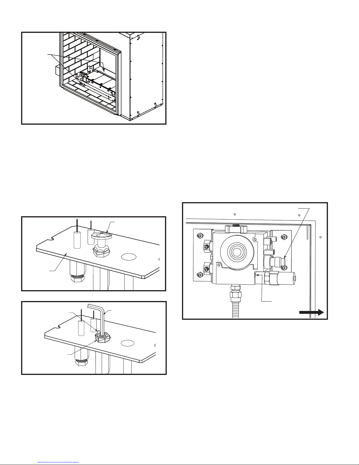
7. Locate the black plastic cap on the gas valve. (Fig.
6) Remove the black cap by pulling the cap straight
off. Note the position of the marker on the top of
the rotary knob. This marker will point to NAT or LP.
(Fig. 7)
Black Plastic Cap
Pilot Hood
Pilot
Bracket
CO133
Fig. 4 Remove pilot hood.
Index Tab
Snap Ring
Fig. 5 Remove pilot orifice.
Allen Wrench
CO134
Replace Pilot Orifice
4. Remove pilot hood by lifting up. (Fig. 4) NOTE: It is
not necessary to remove the pilot tube for conversion.
Minimum Rate
Screw
CO138
Fig. 6 AF4000 Valve in place.
Front of Fireplace
8. To convert the valve from NG to LP, push in the
knob and rotate 90° (1/4 turn). NOTE: The shaft
should point to LP. The shaft will remain pushed-in.
9. Remove the slotted brass minimum rate screw
located in the valve next to the motor drive. (Fig. 7)
10. Replace the minimum rate screw with the one
provided in the LP conversion kit supplied with this
fireplace. Ensure the screw is fully installed.
11. Install the enclosed identification label to the valve
body where it can be easily seen.
12. Reinstall steel panel.
22
 Loading...