

Page 1

Inner Top Replacement
Installation Instructions
Kit #0016
for the Dutchwest ExtraLarge Convection Heaters
General Information
The two-piece inner top kit for the Dutchwest ExtraLarge convection Heater fits 1990-93 units (model
2184, with two front doors) and 1993-97 units (model
2460, with a single front door).
The sides, front and inner back of the stove trap the inner top. Replacing the original style inner top requires a
complete rebuild of the stove. Once the new style inner
top is in place, if you need to replace the insert you can
do so by removing only the stove top.
Work in a clear, well-lighted area. If possible, work out
doors. If you must work indoors, use a drop cloth and
protect the surrounding area. Wear gloves, a dust mask
and protective eyewear.
Kit Contents:
• Inner top casting insert • Inner top insert
• Refractory insulator • 2 pieces of Interam gasket
• Refer to Figure 7 to identify parts.
Tools Required:
• Rubber mallet, or standard hammer and a block of
wood
• 7/16” open-end wrench
• 3/8” cold chisel, or old screwdriver
• Needle-nose pliers (for later units only)
• Wire brush, hand-held or rotary
• Stove cement and putty knife. The easiest way to apply cement is from a tube in a caulking gun. Otherwise, use a putty knife to apply cement from tube.
• Penetrating oil. Use Marvel Mystery Oil, Liquid
Wrench or similar; WD-40 is not strong enough for
this work.
• Automotive anti-seize compound
• Shop Vac with very good filter. Do not use a regular
household vacuum on soot - it is fine enough to pass
right through most common filters.
• Drop clot or tarp
-
Disassembly Procedure
1. Make sure the stove is completely cool before you
begin. Remove ashes and dispose of them properly.
An empty ashpan is a handy tray for hardware and
small parts.
2. Remove the probe thermometer from the stove
top. Some units have a small chrome sleeve on the
probe shaft; be sure to keep track of this if it is loose.
3. Lift off the front door(s) and the side door. You can
remove the doors by wiggling them back and forth,
and lifting at the same time.
4. Unfasten and remove the top. (Fig. 1) A bolt at each
corner holds the top to the rest of the stove body.
There is a gasketed seal between the stove top and
the rest of the body. Lift off the stove top and set it
aside, upside down. Check the gasket for compression or wear; replace if necessary.
Loosen
all four(4)
Bolts Before
Removal
Loosen, then
ST790
Fig. 1 Remove four (4) bolts to release the stove top.
5. Lift out the decorative front brass bar, the refractory
insulator and the catalyst. (Figs. 2 and 3) Be careful
with the catalyst, as it is fragile. Place the insulator
in a sealed plastic bag pending disposal. Check the
combustor for major cracking or crumbling. Refer to
the stove manual for details on evaluating the catalyst.
From this point on, penetrating oil will help to release
hardware. Use automotive anti-seize compound
when you replace hardware, to ease future repairs.
Fig. 2 Remove the refractory insulator.
remove these
bolts
Refractory
Insulator
7001208 8/08 Rev. 3
Page 2
Remove the anchor bolt and nut joining the damper
to the damper adjuster; open the damper or reach
through the firebox to get at the nut. The rearward
bolt in the base of the adjuster is the adjusting bolt;
leave it in place. (Fig. 3)
C-Clip
Washer
Adjusting
Damper Rod
Steel Tab
Anchor
Bolt
Fig. 3 Catalyst, damper and associated parts.
Bolt
Damper Crank
Damper
Damper
Adjuster
Steel Tab
Catalyst
ST792
Remove the two bolts holding the steel tabs which
capture the pivoting ends of the damper, and remove
the damper. (Fig. 3)
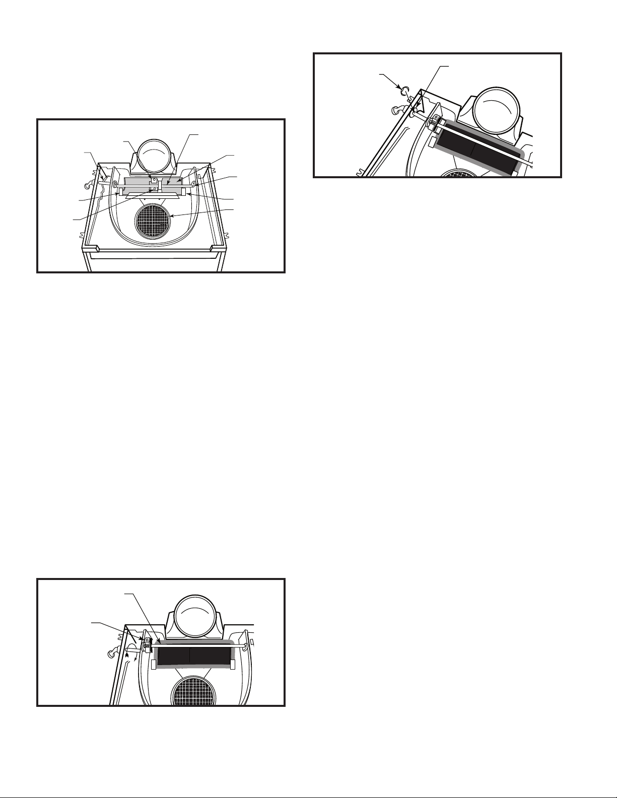
Rotate the damper crank forward and flip the damp
er adjuster upside down. Slide the adjuster to the left
end of the crank. (Figs. 4 and 5)
Check the steel damper rod where it passes through
the left side of the stove. Early style rods have
threads where they pass through the left inner side
of the stove. Later units have a retaining clip in a
groove on the rod, just inside the left outer side. (Fig.
5)
For early units: use the stove door handle to turn the
damper rod and crank counterclockwise (as you
face the left end of the stove), till the rod unthreads
from its threaded hole. As you turn the rod and crank
through the high point of the arc, you will need to
maneuver the adjuster to clear the back plate of the
stove. When the threads on the rod clear the threaded hole, remove the rod and lift out the damper and
adjuster. Note that the illustrations show the later
style of handle, with a permanently-mounted base.
(Fig. 4 and 5)
Damper Crank
Damper
Adjuster
ST793
Fig. 4 For early units, unthread the damper rod from the
damper crank and the inner top’s inner wall.
ST794
Fig. 5 On later units, remove C-clip from damper rod.
For later units: remove the retaining clip from the steel
rod. Pull the rod out of the stove, then remove the
damper crank and the damper adjuster (Fig. 5)
5. Unfasten the stove front. There are nuts and wash
ers on threaded studs on the insides of the front/
sides joints; sometimes these are above the inner
top /front joints. Sometimes they are below this joint
(inside the firebox). There are two studs on each
side.
6. Break the cement seal around the stove front. From
inside the stove, tap outward along the seams
between the front and the stove sides, and between
the front and the inner top. Use either a rubber mallet or a hammer and a wooden block to cushion the
impact. Have a helper hold the top edge of the stove
front to keep it from falling when the cement seal
is completely broken. With the seal broken, lift the
front panel off the stove, and set it down flat, with
its outer side down; do not set it on its bottom edge,
as this can damage the ash door hinges. On stoves
with a single front door there is an air channel and
primary air valve fastened to the inside of the stove’s
front panel. Leave these in place on the stove front,
and be careful to avoid any impact on the air valve
handle.
7. Remove the right-hand side of the stove (as you
face the stove). Inside the firebox, use a wooden
prop to support the inner top. There is a nut and
washer on a threaded stud where the right side
meets the stove back; remove the nut and washer
and leave the stud in place. Tap outward, from inside
the firebox, to break the cement seal. With the seal
broken, pull the side away from the rest of the firebox, and set it down with its inner side up.
8. Now all that holds the inner top in place is the
wooden prop, and cement along its left and rear
edges. Grasp the inner top and wiggle it back and
forth while pulling toward yourself at the same time.
Watch that the supporting prop doesn’t fall out of
place. When the inner top comes loose, set it down
on a protected spot on the floor.
9. Remove the inner top channel cap by unbolting it
(from the underside of the inner top). You may need
2
Page 3

to tap it gently to release it from the inner top. Remove the steel air distributor by wiggling it out of its
socket in the inner top . (Fig. 7)
10. Use a cold chisel or old screwdriver to chip out the
old cement from joints on the right side, the front, the
top edge of the inner back and the inside of the left
side (including around the hole where the catalyst air
enters). Also remove cement from the upper edges
of the inner top channel cap, and from the forward
vertical edges of the panels that form the ashpit.
You do not need to get down to bare metal, but you
must clear a deep and continuous channel so there
is room for the new cement and a good tongue-andgroove joint.
Cement is a clay-based material; it dries and becomes
brittle. Pieces can have sharp edges, so be sure to
wear goggles. It is also dusty, so wear a dust mask or
respirator. If there was originally cement in the joint
between the stove’s right side and the outer back, you
should remove it but you need not replace it.
Reassembly Procedure
1. Do a ‘dry run’ of Step 2 - 6 to familiarize yourself with
them before applying cement.
2. You may notice a gap between the new inner top
and the new insert. There is a piece of ‘Interam’ gas
ket in this gap. Interam is a thin material resembling
felt; when it is first heated it expands greatly, to form
a flexible seal between cast iron parts. Any apparent
gaps will fill when the Interam expands under heat.
Apply cement to the upper edges of the inner top
channel cap. From the top, slide the air distributor
into its slot on the left side of the insert, and fasten
the inner top channel cap to the underside of the
new inner top with its original bolt. The channel cap
must capture and hold the air distributor.
Apply stove cement to the grooves on the left side,
where it supports the inner top, and on the top edge
of the inner back. Apply cement to the inside of the
left side, where the inner top channel cap abuts the
left side. Slip the inner top into position, using a prop
to support its right edge.
3. Apply cement to the grooves on the inside of the
stove’s right side, where it meets the inner top, inner
back and inner bottom of the stove. You do not need
to cement the joints between the right side and the
back or bottom of the stove, since these are not a
seal between the firebox and the room.
4. Put the right side into position, bottom edge first, and
secure it with a nut and washer on a threaded stud
where the side meets the outer back. Be sure the
side engages the inner firebox parts. Gentle pressure from a bar clamp will help ensure the right side
is fully mated against the inner parts.
5. Apply cement to the inside of the front panel, in the
seams where the panel meets the inner top, where
it meets the inner bottom, and where it meets the
stove sides. Also apply cement to the forward edges
of the two vertical walls around the ashpan.
6. Position the stove front on the stove. Lower the bottom edge of the panel into place first, in the channel
on the stove bottom, then swing the panel toward
the stove body. Be sure to avoid any pressure on
the ashdoor. The threaded studs on the inside of the
panel will pass through slots on the forward edges
of the stove sides. Fasten the front into position with
nuts and washers on the two threaded studs on
each side.
7. Install the damper crank and adjuster. Pass the
crank through the adjuster before you put its right
end into a hole in the catalyst chamber wall (the inner wall of the inner top).
8a. For early units: pass the steel damper rod through
the hole in the left side of the stove. Turn it clockwise (as seen facing the left side of the stove) until
its square end engages the square socket in the left
end of the iron damper crank. When the square end
engages the crank, turn both parts together, until
-
most of the threads on the rod engage the threads in
the inner top. While you spin the crank, the adjuster
should be upside down, and at the left end of the
crank.
8b. For later units: pass the steel damper rod through
the hole in the left side of the stove. Place the large
washer on the rod, inside the stove. Then slide the
square end of the rod through the catalyst chamber
wall and into the square socket on the left end of the
damper crank. When the parts are oriented properly,
both the handle and the crank should point downward.
Push the washer against the inside of the stove’s left
side, and use needle-nose pliers to put the retaining clip into the groove in the rod, to lock the rod in
place.
Damper Rod
Fig. 6 Install the damper rod and washer (later units).
Washer
Damper
Crank
ST795
3
Page 4

9. Turn the damper crank to its highest position and
install the damper, secure it at each end with a steel
tab held in place with a hex head bolt. (Fig. 3)
10. Join the damper adjuster to the damper with a hex
head bolt and a nut. The bolt passes through the forward hole in the base of the adjuster; the nut attaches to the bolt on the underside of the damper. Open
the damper or reach through the firebox to reach
the nut. Use the damper handle to test the damper
for smooth operation and adjust as needed; the
rearward bolt in the base of the adjuster regulates
the pressure on the damper. Loosen the forward
(anchor) bolt on the damper. Turn the adjusting bolt
clockwise to tighten the damper. However, do not
overtighten; the metal parts will expand under heat.
The damper should be snug, but not tight, when
the stove is cold. Use a piece of paper between
the damper and its gasket to gauge how tight the
damper is. When the damper is adjusted properly,
tighten the anchor bolt and its nut.
11.Put the catalytic combustor in place in the inner top
insert, with a piece of ‘Interam’ gasket around its bot
tom edge. (Fig. 7) Put the new refractory insulator in
place over the catalyst; note that its forward bottom
edge is slightly relieved in the center, to accommodate the new style insert. The original insulator is not
relieved.
12. Put the decorative brass bar in place in pockets at
the sides of the slot across the top edge of the front
panel.
13. Fasten the outer top into position with bolts and
washers at the corners of the top. The bolts should
be snug, but not tight; overtightening can bow the
top, leading to smoke leakage, and it can also snap
the extensions on the stove sides.
14. Remove any cement which has squeezed out from
any joints onto the outside of the stove. You do not
need to remove squeeze-out on the inside of the
stove.
15. Hand-turn a 1/4” drill bit, through the hole in the
outer top and through the new refractory insulator.
Avoid hitting the catalyst. Replace the probe thermometer, and its chromed sleeve if you took it out.
Do not simply punch the thermometer through the
insulator, this can break off a piece on the underside
of the insulator.
16. On Model 2184 (which has two front doors), make
sure the rocker grates can rotate freely. If they are
jammed, check the position of the loose grate frame
over them. If you need to move this frame, remove
the ‘grate back’ and the right inner half-wall (if so
equipped). Each of these panels mounts with two
hex head bolts. You will probably need penetrating
oil to loosen these bolts. With these two panels removed, prop the rear edge of the grate frame up out
of the way so you can properly position the rocker
grates. Be careful with your hands when you lower
the grate frame into position over the rocker grates.
Replace the grate back and right inner half-wall.
17. Replace the front door(s) and the side door; simply
slide their hinge pins into place on stubs on the front
and side panels. Do not strike them sharply with
any object. You may need to wiggle the doors back
and forth while pressing downward to seat the doors
properly.
18. Let the cement dry for at least 24 hours. When you
fire up the stove, treat it as a new one because of
the new cast iron parts; ‘cure’ it with four to six small
fires before you resume regular burning. Each fire
should be about 100° hotter and an hour longer than
the previous one. Use a surface thermometer on the
side door as your guide to firebox temperatures. The
-
probe thermometer in the stove top registers catalyst
temperatures, which are much higher than firebox
temperatures.
19. Discard the original inner top, baffle and refractory
insulator.
Top
Refractory
Insulator
Catalyst
‘Interam Gasket’
Inner Top
Inner Top
Channel
Cap
Inner Top Insert
Fig. 7 Inner top and associated parts.
Air Distributor
‘Interam Gasket’
ST796
MHSC
149 Cleveland Drive • Paris, Kentucky 40361
4
www.mhsc.com
 Loading...