

Page 1
VCS4006 / VCS4106 / VCS5006 / VCS5016 ASSEMBLY PROCEDURES
Tools Required: knife or scissors, Phillips or Robertson (square head) screwdriver..
Model VCS4106
Shown
Step 1: Unpack Carton and Verify Contents
Use a sharp cutting tool to cut the straps on the packaging and then lift off the carton top. The sleeve
surrounding the barbecue can be removed by lifting it straight up and over the top of the unit.
all contents to the parts list that accompanies this assembly manual. remove the protective plastic
coverings from the metal parts
. Be careful not to scratch or damage the finish of the metal parts when
Next,
Compare
removing the protective plastic. Refer to the parts list for fastener detail.
CAUTION:
Some parts may have sharp edges; to avoid injury, wearing gloves during assembly is
strongly recommended
Page 1
50003825 01/06 Rev.0 En
Page 2
VCS4006 / VCS4106 / VCS5006 / VCS5016 Assembly
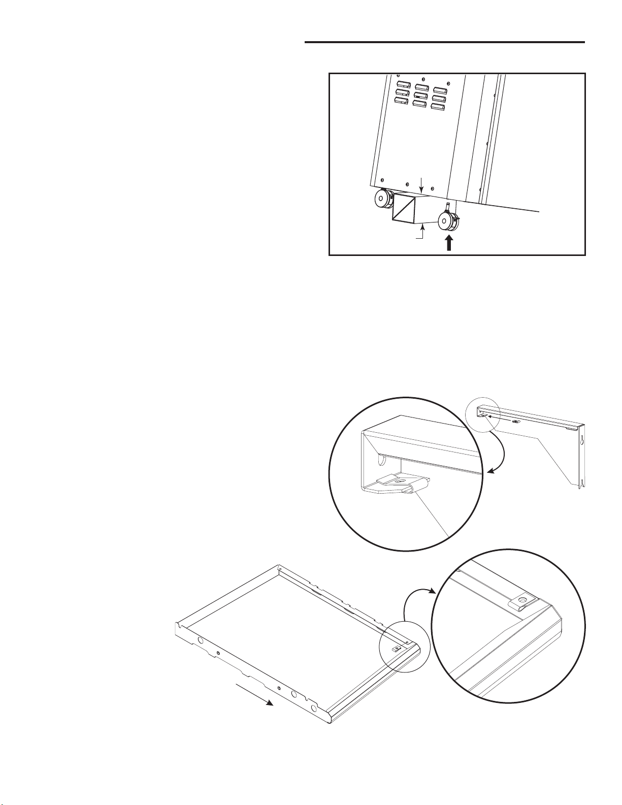
Step 2: Install the Casters
Parts Required:
Note:
Casters (wheels) may differ from those shown in
(4) Casters, (1) Block (not included)
the illustration depending on the model you purchased.
Select a side to begin installing the casters. Place a block
of wood, a telephone book or anything else available approximately 6 inches thick -under the side to support
the weight of the barbecue. Next, insert the pin on the top
of the caster into their respective holes located on the
bottom, near the front and rear corners. If you have any
difficulty snapping them into place, try rocking the
castors in a circular motion. When both casters are in
place, repeat the same procedure on the opposite side.
Step 3: Install U-Clip Fasteners
Parts Required:
(4) #10-20 U-Clip Fasteners
(1) Left Side Shelf Support, (1) Left Side Shelf
(1) Right Side Shelf Support, (1) Right Side Shelf
6” - 8”
(152 - 203mm)
Fig. 2
Install the one (1) U-Clip fastener to each of the Side
Shelf Supports as shown in Fig. 3a. One (1) U-Clip
should be placed on each bracket, with the flat side
down.
Install the one (1) U-Clip fastener to each of the Side
Shelves as shown in Fig. 3b. One (1) U-Clip should be
placed on the under side of each shelf, at the front
outside corner, with the flat side out.
FRONT
Fig. 3a
Fig. 3b
Page 2
Page 3
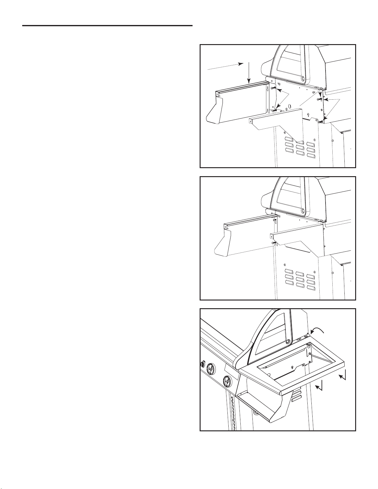
Step 4: Install the Side Shelf Supports
VCS4006 / VCS4106 / VCS5006 / VCS5016 Assembly
Parts Required:
(1) Left Side Shelf Support
(1) Left Condiment Tray
(1) Right Side Shelf Support
(1) Right Condiment Tray
(8) 1/4-20 x 1-1/2“ Bolts
Note:
Only the right side assembly is shown in Fig. 4a
and Fig. 4b. To install Left Side Support and Condiment
Tray, repeat this step for the left side.
On the right side of the barbecue there are four threaded
inserts, screw a bolt half way into each of the four
threaded inserts. You will notice the bottom slot of the
support has a 'Y' shaped slot and a 'keyhole' shaped hole
above it. Take the Right Side Shelf Support and slide the
top screw into the 'keyhole' and the bottom screw into the
opening of the 'Y' shaped slot. Now take the Right
Condiment Tray and align its holes over the two front
bolts and gently push down until the bolts settle into the
grooves of the tray.
Slide
Push
Bolts
Bolts
Fig. 4a
Next: Gently push down on the support until the screw
settles into the top of the groove. Do not fully tighten the
support screws at this point.
Step 5: Attach Shelves
Parts Required:
(1) Right Shelf - S/B (Shown)
(1) Left Shelf - Solid
Place the Right Shelf - S/B (shown) on top of the
supports making sure the holes are aligned and then snap
into place on the supports. The inside lip of the shelf will
slide between the grill shell and the shelf supports.
Fig. 4b
Then Snap
Into Place
Slide End
On First
Fig. 5
Page 3
Page 4

VCS4006 / VCS4106 / VCS5006 / VCS5016 Assembly
Step 6: Secure Shelves
Parts Required:
(4) 10-24 x 1/2” Bolts (black)
Secure each Shelf by inserting (2) 10-24 x 1/2” bolts
A.
through the U-Clip fasteners as shown in the diagram.
Tighten the four (4) Shelf Support bolts from Step 4 to
B.
secure the shelf supports to the grill body.
Repeat Steps5&6fortheopposite side of the grill.
Step 7: Secure Side Shelf to Grill
Parts Required:
(3) 10-24 x 1/2” Bolts (black)
Lift the grill lid and insert two (2) #10-24 x 1/2” bolts,
shown as “a” and “b” in Fig. 7, to further secure the
Shelf Right - S/B to the grill body. Be sure to fully
tighten the bolts before proceeding to the next step.
Fig. 6
A.
Insert
Bolts
B.
Tighten
Bolts
Bolt “a”
Bolt “b”
Next: Repeat Step 7 on the opposite side of the grill’s
interior to secure the Shelf Left - Solid to the grill body
by inserting only one (1) #10-24 x 1/2” bolt in the “b”
location as shown in the illustration.
Step 8: Secure Condiment Tray to Console
Parts Required:
(2) #10-24 x 1/2” Bolts (stainless)
(2) #10-24 Nuts (black)
Secure the Left Condiment Tray to the Console using a
#10-24 x 1/2” stainless bolt and a #10-24 nut. Make sure
the holes of the Condiment Tray and the Console are
aligned. Reach underneath the console and hold the nut
in place with one finger and insert the bolt from the
outside as shown in Fig. 8 and tighten until they are
securely fastened.
Next: Repeat Step 5 to secure the Right Condiment Tray
to the opposite side of the console.
Page 4
Fig. 7
Bolt
Nut
Fig. 8
Page 5

VCS4006 / VCS4106 / VCS5006 / VCS5016 Assembly
Step 9: Attach Side Burner Lid
(S/B-Single)
Parts Required:
(1) Side Burner Lid (S/B-Single)
(2) #10-24 x 3/4” ( 1/4” Shank)*
*
Included with the Side Burner Kit
Attach the lid marked (S/B-Single) to the Shelf Right top
marked VM-S/B using two #10-24 x 3/4” ( 1/4” Shank)
bolts. Align the holes at the back sides of the lid with the
holes located in the shelf top and insert a bolt in each.
Note:
If your unit is equipped with a side burner, please
refer to the instruction sheet included with the side
burner for installation instructions.
Step 10: Attach Knobs
Parts Required:
VCS4006: (5) Knobs
VCS4106: (4) Knobs
VCS5006: (6) Knobs
VCS5016: (6) Knobs
Bolts
Fig. 9
Note:
may require 4, 5 or 6 knobs. is equipped with
four (4) knobs, VCS4006 with five (5), and &
VCS5016
Depending upon your specific model, your grill
VCS4106
VCS5006
equipped with six (6) knobs.
Align the knobs on the valve stems and push inward until
the knob sits snugly on the stem.
Step 11: Remove the Packing Tape
Remove the Packing Tape from:
The Grease Cup
The Base Assembly (inside the grill)
The Warming Rack
Note:
For models VCS5006 & VCS5016, remove the
Packing Tape from the front pull-out drawer.
Fig. 10
Fig. 11
Page 5
Page 6

VCS4006 / VCS4106 / VCS5006 / VCS5016 Assembly
Step 12: Attach the Handle to the Door
Parts Required:
VCS4006/VCS4106: (1) Handle
VCS5006/VCS5016: (3) Handles
VCS4006,
VCS4106
Handle
Note:
Handles may not appear exactly as shown in
diagram
Attach the Door handle(s) to the door(s) by aligning the
handles over the holes and inserting the screws that were
supplied with the handles through the door panel and into
the handles. For models & VCS , attach
VCS5006 5016
the drawer handle using the same method.
Note:
If doors are not aligned or have shifted during
shipping, they can be adjusted by loosening the screws
which fasten the hinge of the door to the grill body and
shifting the doors until they are aligned. Once satisfied
with alignment, fully tighten the screws to secure the
doors into position.
Step 13: Install the Grease Cup and Grease Pan
Parts Required:
(1) Grease Cup
(1) Grease Pan
VCS5006,
VCS5016
Handle
Fig. 12
Install the Grease Cup into the cut-out in the Upper Base
Panel located underneath the grill. It is accessible from
the back of the grill. Once the Grease cup is in place,
move the Grease pan into position above it by placing
the side edges onto the support rails and sliding it into
place.
Note:
Make sure the funnel opening of the grease pan is
positioned over the Grease Cup.
Step 14: Attach Stabilizer Bracket
Parts Required:
(2) #10-24 x 1/2” Bolts (black)
(1) Stabilizer Bracket
Attach the Stabilizer Bracket underneath the bottom
panel by aligning the holes and inserting both #10-24 x
1/2” bolts through the panel and into the Stabilizer
Bracket as shown in Fig. 14.
Page 6
Stabilizer Bracket
Fig. 13
Fig. 14
Page 7

Step 15: Install the Internal Components
Parts Required:
VCS4006, : (4) Sear Plates
VCS4106 (3) Cooking Grates
(1) Warming Rack
VCS5006, : (5) Sear Plates
VCS5016 (4) Cooking Grates
(1) Warming Rack
VCS4006 / VCS4106 / VCS5006 / VCS5016 Assembly
Carefully place each of the Sear plates side by side inside
the barbecue, making sure the semicircular finger groove
is facing toward the front of the grill. Each sear plate
rests just above each burner tube.
Next, set the cooking grates, side by side, on the upper
ledge of the grill tub. Make sure the finger groove is
facing toward the front of the grill.
Set the warming rack into the supports located on either
side of the rear lid.
Note:
One side of the Grate surface has a rounded side
suitable for meats and a flat side suitable for delicate
foods (i.e. fish). Grates can be turned over according to
your preference.
Caution:
Do not attempt to turn Cooking Grate over
while the Grill is in use and grates are hot. Doing so
could result in severe burns and other injuries.
Burner
Sear Plate
Fig. 15a
Warming
Rack
Cooking
Grates
Fig. 15b
Step 16: Install the Battery
Note:
Models , VCS5006 &VCS5016 require a “AA”
Model VCS4106 requires a “AAA” Battery;
VC4006
Battery.
Unscrew the Ignition Button from the console and insert
a battery into the housing by placing the positive side of
the battery in first. Then screw the Ignition button back
into the console.
Page 7
Fig. 16
Page 8

VCS4006 / VCS4106 / VCS5006 / VCS5016 Assembly
Step 17: Install the LP Cylinder (LP Models Only)
Parts Required:
(1) LP Gas Cylinder (not included)
Note:
Check your user’s manual for the cylinder filling
requirements, how to attach the regulator and how to test
for leaks before you try lighting the grill.
Caution:
Make sure the hose is not touching any hot
surfaces.
Note:
For Models VCS5006 & VCS5016, refer to Tank
Pull-out assembly instructions included with the Tank
Pull-out kit.
Place the LP Cylinder into the hole in the bottom panel.
Next secure it from moving by lifting the Cylinder
retainer wire and latching the bent edge over the lip of
the Cylinder. The final step is to connect the to
Cylinder
the .
Caution:
Do not turn on the grill until after performing a
Regulator
leak check at all connection points and fittings. Use a
spray solution of 50% dish soap and 50% water onto all
connection points and fittings. Formation of bubbles
indicates air leaks.
Fig. 17a
Note:
Ensure all plastic coatings have been removed
from all stainless steel parts before using the grill.
Service Note: If you are experiencing difficulties or are dissatisfied with your purchase, please contact CFM at
the telephone number listed above prior to returning your grill to the store.
Fig. 17b
CFM Corporation
2695 Meadowvale Boulevard
Mississauga, Ontario L5N 8A3 Canada
(800) 668-5323
www.cfmcorp.com
Page 8
 Loading...