Page 1
v/4
,s
G600
INSTALLATION
lM PORTANT
ldrt^\lor
,nald
Direct
-
&^ep,
an
ta
6"
Before
silt
vent
AND
Beg
9rlrt
Gas
sy
Heater
OPERATING
inning
Installation,
Read
"s"
Instructions
Carefully
series
SAVE
WARNING:
IS NOT
MAY
FOLLOWED
RESULT
PERSONAL
-
Do
not
store or
this
or any
other
WHAT
-
Open
-
Do not
-
Do
-
Extinguish
-
lmmediately
supplie/s
-
ll
Installdion
THIS
Windows.
try
not
touch
you
cannot
and sewicc
MANUAL
to
ignite
any
any
call
instructions.
reach
FOR
IF
THE
INFORMATION
EXACTLY
CAUSING
TNJURY
gasoline
use
appliance
TO
any
appliance.
electrical
open flame.
your gas
your gas
must
be
FUTURE REFERENCE
OR LOSS
or other
DO
switch; do
supplier trom
supplier,
performed
IF
by a
A FIRE
PROPERTY
OF
flammable
yapors
YOU
not use
a neighbour.s
call the
any
flre department.
qualified
IN THIS
OR EXPLOSION
LIFE.
and liquids
SMELL
phone
ingtallcr,
your
in
phone.
scrvice
Follow
MANUAL
DAMAGE,
in
the
GAS
building.
the
agcncy
Part No.
or
vicinity
gas
gas
rupplier
519549
ol
Rev I
,0glgg
Page 2
CONTENTS
Description
lmportant
Installation
Instructions,
Clearances
Replacement
Glass Cleaning
Venting
Venting
Parts
Planning
Horizontal
Vertical
Cathedral
#1
List
Your
Installation
I nstallation
Termination
Ceiling
Installation
General
Page #
4
5
6
7
7
I
I
9
-
l\
it
10
10
11
13
16
19
20
For Your
Safety,
Lighting
To Turn
Off Gas To Appliance
Maintenance
Parts
Parts
Diagram
List
Fap,
Trouble
Shooting
Warranty
"WARNING:"
SERVICE
REFER
OR
TO
INFORMATION
GAS
SUPPLIER.
IMPROPER
MAINTENANCE
THIS
CONSULT
Before
Instruction
I nstructions
INSTALLATION,
CAN
MANUAL FOR
QUAL|FIED
Lighting
ADJUSTMENL
CAUSE INJURY
ASSISTANCE OR FOR
21
22
23
23
24
25
26,27
28,29
30
ALTERATION,
PROPERW DAMAGE.
ADDITIONAL
SERVTCE
OR
Page 3
-
Study these
Installation
Gas
Maintain
Code,
clearances
IMPORTANT
instructions carefully
conform to Local Codes,
must
ANSI 2223.1
(USA);
for servicing and
and
completely
Canadian
proper
INFORMATION
before
in
or,
the
absence
installation
operation. (See
installation.
must
fotlow
of Local
Clearance
Codes,
CAN/CGA-BI49-1
Section)
with
the Current
or 2
(latest
National
Edition).
Fuel
DANGER:
CARBON
The
rate
This
convert
WAR
IS FACTORY
DANGER:
SUPPLY
EXPLOSION.
MONOXIDE
maximum
is
21,000
heater is equipped
BTU/hr (Natural
heater
the
N ING:
EQUIPPED
CONTAINER
CAUTION:
ERRoRS
cAN cAUsE
"VERIF(
PROPER
oPERArtoN
POISONTNG.
gas
input
rate
with
controls
for
use
with another
coruvenTtNc
MAY LEAD TO
opERATtoN
WILL LEAD TO
LABEL
ALL wtREs
tMpRopER
OPERATION
oF THts AppLtANcE
is 28,000
Gas), 19,000
BTU/hr
and
orifices
type
BTU/hr
of
orratANcE
PERSONAL
oF THts
AppuANcE
GAS
LEAKS
pRtoR
AND
To
DANGERoUs
oN
(Natural
(propane/Lp).
for
gas.
FoR
INJURY
oN
AT
DtscoNNEcnoN
AFTER
GAsEs
Gas),
only
usE
Lp
THE
FoR
wHrcH
26,000
the
wrrH
OR DEATH.
cAs
BTU/hr
type
of
ANy
wrrHour
coNTRoL
wHEN
opERATtoN.
SERY'C'NG,.,
rr
rs Nor
(Propane/Lp).
gas
on the
cAs
orHER THAN
AN
AppRovED
WITH
A hossle|LmT
sERvrctNG
')
EourppED
rating
plate.
"o*rro...
MAy
LEAD
The
minimum
Do
not
THAT
REGUI-AToR
oF FIRE
gas
attempt
wHtcH
Ar rHE
oR
wrnrNc
To
input
to
rr
BROKEN.
PERSON.
DUE
FROM
ANY
APPLIANCE.
CHILDREN
SHOULD
YOUNG
APPLTANCF;'
DO
NOT
INSTALL.ATION
THE
SERVICE
:9YE
BURNERS
WARNTNG:
IT
IS
::5:i:91:llt-1ry-D
:5:Yj:5,-T?.Ll.9TL.oJFlAIrgN.
REPLACEMENT
To
HIGH
TEMPERATURES,
FUBNITURE
PARTS
APPLIANCE
IMPERATIVE
REMOVED
AND
ADULTS
BE
KEPT
CHILDREN
PLACE
CARPETTNG,
CLOTHING
AND
SHOULD
PERSON.
AND
CTRCULATING
ANY
CHANGE
TH
OF THE
AND
DRAPERIES.
FOR
SHOULD
AWAY
TO
SHOULD
OR
REPAIR
BE
MORE
BEDDING
FREQUENT
TO
CL_EAR.
PANEL
THE
AppLtANcE
SERVICING
BE
ALEHTED
AVOID
BE
SHOULD
THISAPPLIANCE
BURNS
CAREFULLY
OTHER
INSPECTED
MATERIAL,
AIR
FLAMMABLE
BE
PASSAGEWAYS
pnovloe
Heven
SHOULD
THE
APPLIANCE
TO
OR
CLOTHING
SUPERVISED
DONE
CLEANING
FoR
BY
A
BEFORE
MAY
ETC. IT
OF THE
OR
ITS
ADEoUATE
oBsrRucr
OF
THE
BE
DONE
sHouLD
MUST
THE
HAZARD
WHEN
MATEHIAL
OUALTFIED
USE
AND AT LEAST
BE REOUIRED
IS IMPERATIVE
CONTROLS
coMBusiloN
BY A
LICENSED
BE
LocATED
BE REPLACED
OF HIGH
IGNITION.
THEY ARE IN
ON OR NEAR THE APPLIANCE.
ANNUALLY
DUE
THAT
APPLIANCE
BE KEPT
CAN BE
DANGEROUS.
AND
OR
our
oF TRAFFIc
PRIOR
SURFACE
THE
TO
CONTROL
CLEAN.
vENilAnoN
;#;ffii';lHllilHH;
rHE
FRoNr
BUILDING.
opENrNG
oF rHE
OUALIFIED
eHffifrJ
TO
OPERATING
TEMPEFATURE
SAME
EXCESSTVE
ROOM
BY
A PROFESSIONAL
LINT
COMPARTMENTS,
AtR.
AppL|ANce
SERVICE
THE
AND
WITH THE
FROM
pRovtDE
on
Page 4
appliance;
The
in the
or,
National
when installed
absence
Electrical
I N
STALI-^ATION
must
be electrically
of local codes, with the current CSA C22-1
Code ANSI/NFPA
TGlatest
edition
I NSTR
connected
(USA).
UCTIONS
grounded in accordance
and
Canadian
Electrical
Code
local codes
with
(Canada)
or the
appliance
Keep
vapours.
Installation
local
the
with
gas
Turn
Do not
lmmediately
control
The
appliance and
during
KPa).
The
appliance must be
valve
p.s.i.g.(3.5
piping
Gas
Code ANSI
system
piping
and
codeS,
during any
with the National
current
supply
use this
call
system
pressure
any
..
KPa).
must be installed in accordance with local
2223.1
supply
systems
area clear and
provision
CAN/CGA
on and check for leaks.
appliance
qualified
a
and any
the heater
will
gas
its individual
testing of
isolated
pressure
(U.S.A.).
damage the controls used on this heater.
free from
for
combustion
Gas
Fuel
-
if
testing of
disconnect or
-
8149
part
any
service
control
shutoff
the
from the
(ln
Canada
1 or
has
technician to inspect the room
which has been under water.
gas
the
combustible
and ventilation air
Code,
2Installation Gode.
ANSI
DO NOT
been
valve must
supply
gas
gas
-
CAN/CGA.BI49-1
isolate
USE
under water.
piping
supply
supply
the heater from
materials,
2223.1
piping
-
OPEN FLAME.
be disconneaed;trom
system
piping
system
codes,
gasoline,
conform
must
latest edition
Use
appliance
pressures
test
at
system
or 2.) During
Do
by closing
at test
with the
or
piping
the
not use
other
and
local
with
-
in the United
and
soap
and
the
in excess
its individual
pressures
latest
edilion
pressure
syslem.
flexible
hose.
llammable
codes or,
States
water solution.
to replace
gas
supply
equal
testing
pressure
The
any
piping
112
oI
manual shut
to or
of the National Gas
ihe
of
liquids and
in
absence
in
or,
Canada,
parl
of
system
p.s.i.g.
less
than
gas piping
to test
used
of
the
(3.5
off
1/2
gas
Unions in
must
Gas
inches
The
Propane/LP
the
The
excessive
Include
servicing.
for
Use
bubbles
lmpoftant:
silicone.
resistant to the
be
piping
water
maximurn inlei
gas
must have a regulator which reduces the
control will not
a
gauge
test
a soap/water solution
which indicates
lines
must be
column
gases.
pressure.
manual shut-off
Include a drip leg
connection immediately
Atl references
should
action of
ol sufficient size to
for
natural
gas pressure
lf this heater is to
operate with
device and union
or a liquid
gas
to siliconing should
be of
gas
and a
leaks.
the
liquefied
or
to
lhe
gas
plugged
ground
be supplied
upstream ol
gas
joint
type. Compounds
petroleum gas.
provide
11 inches for Propane/LP
heater must not
line
118 inch NPT
leak detector to
a minimum
with
gas pressure
pressure
in the line
the
be adhered
exceed
gas (bottled
LP
directly from
the control
so
tapping
gas
supply
coat
to. Always use
used on
natural
10.5
to between
each
gas
gases
in the
for the
inches for
propane)
tank and may
the
or heater may
line.
connection
joint
threaded
pressure
purpose
naturalgas
the tank
11
and
The tapping must
to the
in
piping
the
600"F
ioints
the
al
of inpul
or bottle supplying
13 inches
leak
be
appliance.
system.
(316"C)
piping
gas
of
appliance of
adjustment.
and 13 inches for
water column.
gas
due
disconnected
be accessible
and
temperalure
high
4.5
to this
for
look lor
Page 5
'l:t
i;
CLEARANCES
For
determined
LEFT
purpose
the
when
Combustion
SIDE
orientation,
of
facing the
ventilation
front
TO
the left
the appliance.
of
COMBUSTIBLES
and right
air
should
TOP
sides
of
not be
this appliance
obstructed.
RIGHT
SIDE
are
NOTE:
other
panel
than
extending
LEFT
SIDE
RIGHT
BACK
TOP
FRONT
FLOOR
REAR
When installed
wooden
flooring,
SIDE
CORNER
directly
on
the
appliance
and
depth
carpeting,
of
6
tile
shall
the
appliance.
6rt
6rt
6"
24"
36"
0"
4"
or
other
be
installed
combustible
on
a
metal
or
material
wood
Page 6
{
*'
3-,
I
5
a.
:
i
LOG
IMPORTANI
evidence of
Refer to
WARNING:
carbon,
log assembly
ONLY
SHALL
ASSEMBLY
fne logs
or
diagram
MUST
blackening
for correct
GLASS
MANUFACTURER
REPI-ACED
BE
SUPPLIED
AS A COMPLETE UNIT.
placed
be
on the
exactly
logs,
they
shown.
as
may
be incorrectly
method.
REPI-ACEMENT
REPLACEMENT
DO
PARTS
NOT USE
GLASS
SUBSTITUTE
PANEL.(SEE
lf
there
is any
placed.
MATERIALS OB
LIST)
CUT
1.
Turn off
2. Remove
3. Remdve
4. Remove the
5. Lift the
Take caution
performing
6. Lay
7.
8. Check
9. Reinstallthe
10. Re-attach
1 1.
12.
WARNTNG:
BROKEN
POLLUTION.
a thin
Place
Relight
Panels
Side
panel,
ALL GI.ASS PANELS
GLASS OR
pilot
and remove the trim.
four screws in door
the six screws
panel
from the
glass
frame
this
bead of silicone
glass
firmly in
again that the
door by replacing
lhe
outer trim.
pilot
and check
-
remove
replace trim and front
DO NOT ABUSE DOOR GLASS,
pieces
when removing,
task.
the
glass
WITH
G1ASS
trim
lrom
frame
main
front
center
the
and lay it on a
unit
glass
and
we
(600"F+)
is correctly
burners operation.
glass panet
panel,
MUST BE INSTALLED
around the frame.
allow t hour to
and
six screws.
attach
PANELS OFF
panel.
glass
padded
out of the
recommend using
installed in the door
Tighten firmly.
and side
screws.
wilh
AS THIS COULD
SUCH
AS DROPPING
7
flat
door frame.
dry.
trims.
remove
DURING
surface.
glass
NOTE:
leather
frame'
OPERATION. NEVER OPERATE
THE
Broken
gloves
side
LEAD TO DANGEROUS
GI-ASS
and salety
glass
and
OR STRIKING
is extremely
glasses
replace with
THE
sharp-
when
glass
new
WITH
lT
INDOOR
GI.ASS.
AIR
Page 7
GLASS
CLEANING
NOT
WARNING:
1.Turn
2.Remove
3.
WARNING:
.with
5.Feplace
e.Reiight
I
READ
INSTALLATIOT.I.
DAMAGE
DO
off
Pilot.
four
Remove
gt6ss surface
six
NOT
DO
a soft
door
pilot
VENTI
INSTRUCTIONS
ALL
LOSS
OR
CLEAN
screws
screws
USE
rag
and
by
and
in
ABRASIVES
paPer'towel
or
wipe
reversing
check
NG'l:,'J,flhT*Ii?,i,[B\OCEDU
FAILURE
LIFE.
OF
GLASS
door
in
center
off
main
TO
WHEN
trim
glass
ON
use
surface
until
the operation
burners
COMPLETELY
SO
DO
HOT'
remove'
and
panel
GLASS
regular
is dry'
operation'
AND
COULD
remove
and
SURFACE.
glass
remove
to
RESULT
cleaner,
door.
THOROUGHLY
IN
panel'
spray
BEFORE
SERIOUS
glass
the
RE
ATTEMPTING
INJURY
cleaner
on
I
PROPERTY
VENT
NOTE:
THE
PA|NTTocooRD|NATEw|THTHEEXTER|oRF|N|SH.
NOTE:
NOTE:
NOTE:
SEAL
(316'C)
BEFORE
stLtcoNE
ENSURE
PIPES
OPERATION
COULD
VENTING
REFER
AFTER
HIGH
CONNECTIONS.
ALL
OF
EVERY
JOINING
SEALANT
THAT ALL EXCESS
THESE PIPES ARE
AS
RESULT
TERMINAL
A
HAS
TO GRAPH
ANY
TEMPERATURE
THE CONNECTIONS
TIME
OF IMPROPERLY
IN
MAINTENANCE
A VENT
ELBOWS
(cE
SERIOUS
MAY
INCH
ONE
PAGE
ON
SILICONE
CONNECTION
AND
106/LOCT!TE
Rn/
SEALANT
VISIBLE
INSTALLED
INJURY
PAINTED
BE
CLEARANCE
(Ftc.1) FoR
11
REOUIRING
WITH
PIPES
ONCE
APPLY
IS CAREFULLY
PROPERTY
WITH
TO
MUST
HIGH
lS MADE-
81s8s)
RTV
INSTALLATION
THE
AND
DAMAGE
450"F
COMBUSTIBLES.
INSTALLATION
DISCONNECTION
BE
TEMPERATURE
BEAD
A
MAINTAINED
(232'C)
USED
OF
END
TO
CLEANED
LOSS
OR
HEAT
VARIABLES.
TO
SILICONE
HIGH
OF
OFF
IS COMPLETE.
VENTING
RESISTANT
VENTING'
OF
RE-SEAL
TEMPERATURE
ELBOW
THE
OF
OR
EXTERIOR
LIFE.
ALL
(6OO"F)
PIPE.
SYSTEM
Page 8
GLASS
CLEANING
NOT
WARNING:
1.Turn
2.Remove
3.
WARNING:
4.with
5.Feplace
e.Reiight
I
READ
INSTALLATIOT.I.
DAMAGE
DO
off
Pilot.
four
Remove
gt6ss surface
six
NOT
DO
a soft
door
pilot
VENTI
INSTRUCTIONS
ALL
LOSS
OR
CLEAN
screws
screws
USE
rag
and
by
and
in
ABRASIVES
paPer'towel
or
wipe
reversing
check
NG'l:,'J,flhT*Ii?,i,[B\OCEDU
FAILURE
LIFE.
OF
GLASS
door
in
center
off
main
TO
WHEN
trim
glass
ON
use
surface
until
the operation
burners
COMPLETELY
SO
DO
HOT'
remove'
and
panel
GLASS
regular
is
operation'
AND
COULD
remove
and
SURFACE.
glass
dry'
remove
to
RESULT
cleaner,
door.
THOROUGHLY
IN
panel'
spray
BEFORE
SERIOUS
glass
the
RE
ATTEMPTING
INJURY
cleaner
on
I
PROPERW
VENT
NOTE:
THE
PA|NTTocooRD|NATEw|THTHEEXTERIoRF|N|SH.
NOTE:
NOTE:
NOTE:
SEAL
(316'C)
BEFORE
stLtcoNE
ENSURE
PIPES
OPERATION
COULD
VENTING
REFER
AFTER
HIGH
CONNECTIONS.
ALL
OF
EVERY
JOINING
SEALANT
THAT ALL EXCESS
THESE PIPES ARE
AS
RESULT
TERMINAL
A
HAS
TO GRAPH
ANY
TEMPERATURE
THE CONNECTIONS
TIME
OF IMPROPERLY
IN
MAINTENANCE
A VENT
ELBOWS
(cE
SERIOUS
MAY
INCH
ONE
PAGE
ON
SILICONE
CONNECTION
AND
106/LOCT|TE
Rn/
SEALANT
VISIBLE
INSTALLED
INJURY
PAINTED
BE
CLEARANCE
(Ftc.1) FoR
11
REOUIRING
WITH
PIPES
ONCE
APPLY
IS CAREFULLY
PROPERTY
WITH
TO
MUST
HIGH
lS MADE-
81s8s)
RTV
INSTALLATION
THE
AND
DAMAGE
450"F
COMBUSTIBLES.
INSTALLATION
DISCONNECTION
BE
TEMPERATURE
BEAD
A
MAINTAINED
(232'C)
USED
OF
END
TO
CLEANED
LOSS
OR
HEAT
VARIABLES.
TO
SILICONE
HIGH
OF
OFF
IS COMPLETE.
VENTING
RESISTANT
VENTING'
OF
RE-SEAL
TEMPERATURE
ELBOW
THE
OF
OR
EXTERIOR
LIFE.
ALL
(6OO"F)
PIPE.
SYSTEM
Page 9
VENTING
INSTRUCTIONS
THESE
SYSTEM
IMPORTANT
STALIATI
I N
The
The
from
.Installation
.
Unauthorized
INSTRUCTIONS
USED
Century
warraniy
of the
any
WITH
Read all
follow
will void
for specific
may vary
PRECAUTIONS:
ON
Heating
will be voided,
following actaons.
of any
damaged
THE CENTURY
these
THE SIMPSON
APPLY
TO
HEATING
instructions
instructions
warranty.
the
venting
from one
is an engineered
and
serious
venting component.
of the
venting system.
carefully
may create
Be sure
clearance
and
appliance
product
fire,
G6OO.
before
to
to another.
starting
a
follow
combustible
to
that
health,
or
DURA.VENT
installation.
the
or
fire
these
has
other
other
been
safety
safety
installation
requirements,
designed
hazards
,i
DIRECT
Failure
hazard, and
instructions
and tested.
may
VENT
to
which
result
lnstallation
.lnstallation
Consult
of
other
your
any component
than
as
local building codes
Atways maintain
combustibles
insulation Be sure
requirements
combustible
requirements from decks,
inlets, and
instructions
gas
Ihe
outside of
separate
appliance
systems
part
instructed
to
between
surfaces.
public
and
appliance
the
sotid
must use it's own separate
prohibited.
are
not manufactured
by these
before
required clearances
prevent
to check these
local building codes.
and
building, and never
tuel or
instructions.
beginning
a tire
the
outer
Be sure to
windows,
walkways,
vent
gas-burning appliance.
hazard.
?S specified
system
approved
or
installation.
(air
Do
instructions
walls
check
be attached
of the
the
soffits,
must
vent
vent
Century
by
spaces)
fill air spaces
not
for minimum clearance
vent
termination
gas
regulatorS,
in these installation
vented directly
be
to a chimney seruing
This
system.
Heating.
to
pipe
and
direct
Common
nearby
nearby
clearance
supply
air
vent
to
with
the
a
gas
vent
:1:
:i,
E--
Page 10
r
SAFETY
PREcAUTIoNS
FoR
I
.Wear
.Exercise
.Be
The
installatiorr
decorative
concealed locations
the
ceiling
require
approved
gloves
aware of electrical
Simpson Dura-Vent
roofline.
support
vertical
Number
9088
9078
906
9068
904
9048
903
9038
902
9028
9118
945;"
9458
990
9908
and
safety
extreme
of both horizontal
black,
Decorative
for
use
caution
as well
boxes.
rise
with
Description
Pipe
6"
9"
Pipe
12" Pipe
12"
Pipe
24" Pipe
24"
Pipe
35" Pipe
36"
Pipe
48"
Pipe
48" Pipe
11"
to 14-518"
Adjustable,
45'Elbow
45'Elbow,
90"
Elbow
90'Elbow,
glasses
when
wiring locations
for
using
PARTS
Direct Vent
and vertical
galvanized
as
such
as
attics,
brass
Snorkel
on the
the
Length, Black
Length, Black
Length
Length, Black
Length
Length,
Length
Length,
Length
Length,
or
chrome
terminations
building
Gentury
Black
Black
Black
Pipe,
Black
Black
Black
Heating
protection.
ladders
in walls
LIST
System
finish.
or spaces
exterior.
otfers
The
trim
G000.
Number Description
940
941
943
g43S
gS3
gG3
g8B
g8l
982
984
gB3
950
or
roof
on
and ceilings.
tops.
#1
a complete
installations. Many items
galvanized pipe
where
kits
are available for
The components
corrosion is a factor,
available
are
,),
Round
Cathedral
Flashing,
Ffashing,
Snorkel
Snorkel Termination (1
Horizontal
Vertical
Vinyl
line
of component
and
fittings
for
both wall
applications
listed
Support
Ceiling
0/12
to
to 12112
Termination (36")
Square
Termination
Siding Standoff
are
offered
are used for
such
below
BoxA/Vall
Support
6/12
Termination
as above
thimbles and
which may
have been
Thimble
Roof
Roof
4")
parts
Box
Pitch
Pitch
for
in
STARTER
-90"
-Horizontal
-24"
-11"
KIT
Black
Black
-
14-5/8'Adjustabte
xA"
-
Horizontal
Elbow
Termination
Pipe
Wall
Thimbte
Cap
Black
Termination
pipe
10
Part
#971 Kit lnctudes:
Page 11
PLANNING
YOUR
":$h*G'*
INSTALLATION
VEFTICAL
TERMINATION
COLLAR
STORM
FIGURE
1
ROTJND
SUPPORT
8ox/wALlTHIMBLE
I
t
ptpF.
l.ENqrH
PIPE
I.ENGTH
CATHEDRAL
CEILING
suPPoFT 8OI
FIGURE
2
I
er
t:
ljrr
:l:
!::
Yt
5i
:+
€.,'
THERE
When
length
wall
horizontal"
vertical
the
and
applications,
the
ARE
11
2l
TWO
,'
Horizontal
Vertical
planning
of vent pipe
thickness.
type
installations,
ceiling,
allow
the
for
firestops
attic,
additional
BASTC
TYPES
Termination
Termination
your
Select
installations.
instattation,
for
your
the
particular
amount
To determine
measure
ceiling
sufficient
thickness,
vent height
are required
pipe
and elbows
OF DIRECT
(Fig.
(Fig.
1)
2)
it will
VENT SYSTEM
necessary to
be
requirements.
vertical rise desired for
of
length of
the
the distance from
the verticat
rise in an
above
at each floor
wiil be
11
required.
level.
INSTALLATION:
select
vent
the
apptiance
pipe
attic or
the roofline.
lf
an offset is
proper
the
to note the
"vertical
-
required
flue
second
For
outtet
story
two-story
needed in
to
for
-
to
Page 12
29
2A
27
26
25
24
23
NOTE:
tested
Unit
ol
vertical
to
30'
PiPe.
The Century
for
minimum
a
horizontal
This
includes
Heating
run.
thickness.
The maximum
vertical
rise.
has
wlth a maximum
rise
1'
stove
G600
clearances and
horizontal run
been tested
wall
is 6'
with 2'
1'
22
21
20
319
E
t
E18
g
';
17
e
5ts
ul
Hls
6tq
ff13
12
To vent
this
please refer
unit
to
within these
chart
figure 1.
dimensions
2CMN(IMUM
WAIITTIICKNESS
4'MINIMUM
wAtrTH|C|(NESS
6'MINIMUM
CI.EAFANCE
FTAMMABI.EWALI.
FROM
123456
TOTAL
Face of Erllrior Wrll
Oo
HORIZONTAL
The maximum
permitted per
side
The maximum
permitted
Vertical
On
allowed.
are
per
side wall
installations two
FIG.
FEET
Ercludlng Elboilr)
number
number
of 90 degree
wall installation is one
45 degree elbows
of
installation is one
(2)
1
elbows
(1).
(1).
45' elbows
is very
Since
system
it
maintain
combustion
exhaust
configurations
adhered
The
vertical
help
to.
graph
and horizontal side
determine the
to
allowable.
12
air intake
certain
apply
showing
important that
its balance
and the
limitations
and
must
the relationship
wall
various
venting
the
between
flue
to vent
as
strictly
be
between
venting will
vent
lengths
the
gas
Page 13
H ORIZONTAL I NSTALIATI
ON
Step
Step
1. Set
2.
NOTE:
1) Twist-lock
.
2')
lhe appliance in
Check
rafters are in
system
may
appliance.
Vent
special
the desired
elbows to the
seams
much out of view
located on
fittings,
the
by orienting
they match and slide
the male
sections
lock
one-quarter
fully locked.
be visible
pipe
examining
Horizontal
every
for
to determine if wall
the
is
attached. lf
want
pipe
male
one
or fittings.
three feet. Wall
this
to adjust
and fittings are designed
twist-lock cohnections. Assemble
combination
appliance
oriented
are designed
ends of adjacent
completely together, then
section clockwise
the inside of the
purpose.
towards the wall
as
procedure:
female
the
four
the
ends
turn, until the two
The
from the
runs of vent
(Fig.
female
They
way when
possible.
it's desired
studs
this is
the
Four
ends of
to slide straight
pipe
into four entry slots
5).
locking
outside, on the
may be located
must be
Straps are available
the case,
location
of black
adaptor with
pipes
indentations
Push the
approximately
female ends.
location.
or roof
the venting
you
of the
with
pipe
and
pipe
or floor, as
indentations,
pipes
and fittings,
sections
lugs will
supported
and
onto
pipe
twist-
not
black
so
on
are
by
5
;iFlG'
ru
l---l!-4
ITI
L^-/\)
FIG.6
\*-ffi
$
MALE
LUGS
LOCKING
Step
3.'With pipe
stove
minimum
mark
centre
with
shown
inch
the
penetrated
combustible
concrete,
acceptable.
into
the
wall
of
the
center-line
in
square
vent
will
attached to
it's
correct location,
clearances
for a 10-inch
the
square hole
Figure
a 7-inch
6. Cut and frame
hole in the
be terminated.
is constructed
material, i.e.
the
to combustibles
of the horizontal
diameter
stove, slide
insuring
square
should line
exterior wall
lf the wall
masonry block
hole. The
pipe,
the 10-
where
of
hole
the
and
up
as
being
non-
or
is
F
I
tJ
0
Page 14
NOTE:
1)
2l
3)
horizontal
The
towards
run
temperatures
cause
The
local
The
For
and
high
locaiion
nationat
and
terminal
vent
installations
36-inch
tall
procedures
Termination
drainage
must
must
Termination.
vent
of
run
termination.
the
of the
horizontal
building
shatl
requiring
Snorkel
used
as
be
provided to
be
not back
Do
must
be
Never
may
and
vent
codes,
recessed
be
not
vertical
a
ierminations
for standard
installed
below
fill around
have
level,
present
or
allow
the
the
termination
and
rise
must
are
not
a
into
the
on
available.
Horizontal
grade,
prevent
snorkeltermination'
the
1/4-inch
a
vent to
possibility
an
on
easily
be
wall or
siding.
exterior
Follow
rise
downward.
run
a
of
exterior
blocked
of the
the
Terminations.
(i.e. basement
water
FIG.7
from
entering
for every
1
This
fire'
must meet
wall
or obstructed.
Refer
building,
same
to Fig-
3.
1
installation
lf the Snorkel
applications),
lhe snorkel
of
foot
could
all
-inch
proper
Step
4. Position
'
NOTE:
1)
2l
horizontal
the
10'inch
the
centre
the
attach
wood
Vent
the
a bead
run
around
a seal
the
on
Insure
combustible
of
exterior
the
to
screws
provided. Before
Termination
of
it's outside
between
it
ient cap
that
ProPer
materials
non'hardening
and
should
(Fig.7)
The four
wood
be replaced
for stucco,
screws
with
brick,
concrete,
of siding.
,,For
'
buildings
Siding Standoff
with
(Part
installed between
exterior
Siding
wall.
Standoff
(Fig.
to
Termination. The
prevents
excessive
melting the vinyl siding
vent termination
with
hole,
the
square
wall
attaching
to the
edges, so
the
exterior
as
wall.
pointing
be
The arrow
clearances
maintained.
are
provided
or
other
fasteners
appropriate
vinyl siding,
950),
should
the vent cap
8) Attach
the
the Horizontal
Vinyl Siding
heat
from
material.
in
and
four
wall,
mastic
make
to
up.
to
should
types
Vinyl
a
be
the
and
Vinyl
Vent
Standoff
possibly
FIG.8
b-{
SCREWS
6
Step
Before connecting the
5.
vent
the black
over
pipe
the
the
to
decorative
pipe.
vent
horizontal
vent
termination,
wall thimble
run
slide
cover
14
of
VINYL SIDING
STANDOFF
Page 15
rE
''*l'
l_/_
ffi
rE
-]
*l-l-
I r-1
o
=
?
?
A
I
o
o
(,
!.3
€l
igtiiii$,i
o
UJ
E
=
IE
u,
c
o
z
.4
c,
E|C
tro
=\
E3
€3
=o
Eb
e=
-9 rE
s
s
F €E
z
=
TE
ul
ut
E
iiiggigiiii,
ul
I
3
lu
TE
itsE$;l=sssEsFs5
1
+{{
UJ
Y
=
a
4
o.
:)
o
a
igiit*Et
@
z
=
liglFgIggF*
UJ
z
u,
:
E
,|lT*
$3
t
;E
:
fF
E
; E6
-o
€ tro
o 3E
rE SE
9 :E
O
-r'l
'=
6e;
rE
!
85
be
'3^
=
i Eg
E
33
sE
G
$;:
gB
E
5;E
g.
iE
ggi
E
Ic=a
o;it c
c5g:
EJZ
Figure
-
Vent Terminal
3
15
E$rt
iglliiiiiigil
-crE+|,'
-CC|a
GOOG
sE$ia$s$gt$i$$E
{{3A,|l,1"
Locations
Page 16
Step
appliance
SliOe
6.
towards
vent
important that
the
the
pipe
wall,
into
the
the
the vent cap sufficient
resuft in a
minimum
inches. Secure
vent
the
attaching
extending
into the
siliconer'
sheet
the strips
remaining
back
towards
concealed
cover.
pipe
the
from
outer
vent
metal
to
portion
by the
(Fig.
9)
two sheet metal
connection.
screws
the
the
and vent
carefully
vent
cap
vent
pipe
assembly
inserting
assembly.
extend into
distance so as to
pipe
connection
the
and
the vent
overlap of
1-114
between
caP by
strips
vent
the
uiall of
provided
Pipe Section.
of the sheet metal
vent
cap assembly
the
Use
vent
pipe,
the two
to connect
Bend any
strip
cap, so it will
decorative wall thimble
the
lt is
WALL
THIMELE
STRAP
be
Step
7. Sliae the
wall
provided.
chrome
Step l.Check
clearance (air
passing
,'enclosures,
combustible
with
maximum
any
offset
venting
decorative
wall
surface and attach
Apply decorative
trim if
desired.
(Fig.
VERTICAL
these instatlation
spaces)
through
attic rafters,
surfaces. Do not
insulation.
vertical
maximum
must
graph.
Check
rise
horizontal
fall
within
(Fig.
instructions for required
ceilings, walls,
of the
t)
thimble
up
the
with screws
brass or
10)
to combustibles
other nearby
or
these
venting
pack
instructions
air spaces
system,
offset limitations.
parameters
the
of
FtG. 11
when
roofs,
for
and
Any
the
Step 2. Set the
plumb
a
of the
where
small hole
gas
appliance
bob
down from
appliance
flue
the vent will
at this
point.
in
it,s
desired location.Drop
the
ceiling
exit,
and
penetrate
Next,
position
the
to
mark the
location
the ceiling.
drop a
plumb
16
Drill
bob
a
Page 17
from
the
in
the
ceiling,
the vent
if
ceiling
framing
You
may
or to
cutting
offset,
loadbearing
roof
to the
penetrate
will
joists,
will
obstruct
wish
as
hole
and
mark
the
roof
the
relocate
to
shown in
members.
previously
the
spot where
roof.
Determine
rafters,
venting
or olher
system.
the appliance,
Fig. 13,
to
drilled
avoid
Step
3.
Step 4.
Step
5. Cut a
to
install
Thimble
square
hole
drilled
shown
Assemble
Pipe
and
the
Appliance
Round
the Round
in
hole in
in
Fig.
the desired
Elbows necessary
Support
and Elbow
twist-locked
hole
in
drill
hole
the
minimum
to
combustibles.
placed
hole
should
Supporr
a flat
in
12.
connections
position.
the roof
be
ceiling,
the ceiling,
Step
2. Frame
lengths
adaptor
Box. Insure
centred
in
the
roof
of
sufficient
requirements
cut
centred
the
to reach
up
through
that
are in
on
in
Step
size
for
BoxMatl
a 10-inch
on
the
hole
as
of Black
from
the
pipe
all
their
clearance
the
2. The
to
fully
small
meet
,\
,\
FlG. 14
Step
6.
NOTE:
1)
2l
Connect
through
lf
an
support
possible
a
hole.
offset
the
separation.
Whenever
less
restriction
section
of
is necessary
pipe
vent
wall
possible,
to the
use
flow
pipe
and
in
every
Straps
45"
of flue
extend
the
attic
3 feet,
to
are
Elbows
gases
17
up
to avoid
avoid
available
instead
excessive
for
of
and intake
obstructions,
stress
this purpose.
90' Elbows.
The
air.
it
is important
on
the
ElLows,
(Fig.
13)
45"
Elbow
to
and
offers
Page 18
Step 7.
flashing
the
Stip
protruding
base
roofing
overlaps
shown
least
combustibles
through
of the
nails.
the top
in Fig.
the
Flashing to
Insure the
minimum'
at
over the Pipe
the roof.
roofing material
edge of the
Verify
14.
that
the roofline.
Section(s)
Secure the
the roof
Flashing
you
with
have
as
at
clearance to
FtG. 15
DIM€NSION'H'
OETAINEO FROM
cAN/cGA-8l.9
oR ANSI
2223.1
OR
H
LOCAL
CODES
Step
Step
8.
9.
NOTE:
1)
2l' Any
Continue
height of
to
the
Vent Cap meets
Pipe
add
minimum building
Fig. 15. Note that
described
roof
pitches,
increased. In
nearby trees,
pitched
can result
ln these cases,
may
solve this
Twist lock
For
multi-story vertical
in
vent height
the
high wind
adioining
roofs, and other similar
in
poor
draft,
increasing
problem.
the Vent Cap.
Ceiling Firestop (Part
the
second floor,
floors. (Fig.
framed
to
dimensions,
.shown
in Fig. 12.
occupied
including
which
be
enclosed.
framed
closets
the vertical
and
construction
the
allowable
of
surfaces
of
instructions
clearance
the
vent
of the
the
required
16)
10-inch
in the same
sheetrocked
materials,
pipe,
and any
The opening
areas
above the first
and storage
passes
The
for
between
and
enclosure.
air
spaces
Sections
code
until
requirements
for steep
must be
conditions,
rooflines,
steep
factors
down-drafting.
or
the vent
height
installations,
963) is required
subsequent
should be
x 10-inch
inside
manner
floor,
spaces,
through,
enclosure
with
however
must
may be
standard
consult
the minimum
the outside
the combustible
Do not fill
with insulation.
the
the
a
at
as
any
FlG.,16
:\
,)
y'r
CLE^RANCE
I
INCH
CLEARANCE
1 INCH
18
Page 19
f
cATHEDRALcEtLtNG
INSTALLATIoN
f
Step 1.
Step 2.
'
Step
Step
3.
4.
rollow
Vertical
Using
line
and
.
and roof
locate
of the
Remove
as necessary
for
larger
Lower
in
the
Box
ceiling. (Fig.
both
level.
place
the roof
installation
Terminations.
plumb
the
of the
drill
the Support
roof
protrudes
vertically
Temporarily
through
venting
a small hole
at this
the drill
Cathedral
shingles or
than the
the
Support
until
sheathing.
Steps
bob,
system
through
point.
hole
and mark
Ceiling
other
to cut the
Box.
Support
Box
the
bottom
at least
17)
and
the inside
2 inches
Align
horizontally
tack the
1 and
mark
on the ceiling
From
Support Box.
roof
rectangular
Cut
the hole
Box
ouiline.
through
of
the Support
Support Box
walls
2 under
the centre-
the
ceiling
the
the
outline
covering
the hole
the
Support
below
with
and
roof,
hole
1lg
the
Box
a
in
into
PATTERN
BOX AS
ONTO ROOFLINE
OF SUPPORT
IT IS
PFOJECTED
Step
Step
5. Using
the top
fold
sheathing.
'ttre
mastic
Support
Box
combustible
Support
6.
Comptete
Installation
procedures
for
tin
the
roof,
and
Vertical
snips,
corners
resulting
run
around
Box,
Box.
cut
down
(Fig.
Terminations.
18)
a bead
the top
to make
the roof.
material
the
by
following
outlined
the Support
to
the roofline,
flaps
Carhedral
in
over the
Before
of non-hardening
edges
a
seal between
Clean
from
Steps 4
Box from
naiting
out
inside
the
through
19
and
rool
it
to
of
the
the
any
the
Ceiting
same
9
FlG. 18
E_
Page 20
GENERAL
MAINTENANCE
inspection
Conduct
Recommended
1. Check
2. Remove
3. Check
.
an
to
areas of
for corrosion.
extreme
replaced.
bird
forming in the
Continuous condensation can
fittings. lt may
elbows, and
weather.
nests,
cases,
the C"p,
or
for
evidences of excessive condensate,
the venting
of
inspect are as follows:
Venting
the
These will
holes. These
and shine a
other foreign material.
inner
be caused by having excessive
exterior
liner,
portions
System
appear as
and subsequently
which are
rust
components should
flashlight down
cause
of the system
spots
;i
corrosion
semiannually.
exposed to the
or
streaks, and
immediately
i
the Vent.
such as water
dripping out
of caps,
lateral runs,
being
Remove any
exposed
etements
in
be
droplets
joints.
at
pipe,
too many
and
to cold
4. Inspect
disturbed,
supports
)
...
joints,
and consequently loosened.
such as
to
Wall
verify
Straps,
that no Pipe
plumbers'tape
or
Sections
Also check
Fittings
or
for rigidity.
have been
mechanical
20
Page 21
IFOR
YOUR
SAFETY,
READ
BEFORE
LIGHTINGT
WARNING:
explosion
life.
A.
B.
may
This
pilot,
BEFORE
Be
than
lf
result,
appliance
follow
sure to
air and will
WHAT
Do
not
try to light
Do
not
your
Extinguish
lmmediately
Follow
lf
building
you
cannot
the
you
LIGHTING
do not
causing
these
smell neril to
settle on the floor.
TO DO
touch
any electrical
any
open flame.
your
call
gas
supplier's
reach
follow these instructions
property
piezo
instructions
smell all
ignition
around the appliance area for
the floor
IF YOU
the
appliance.
switch;
gas
supplier
instructions.
your
gas
supplier,
damage,
pilot
exactly.
because some
personal
light. When lighting
SMELL GAS
;
i
do'hot
from a
exactly,
injury
gas
is
heavier
use any
neighbour's
phone
phone.
a
fire or
or loss of
the
gas.
in
c.
Use
Never
dont
attempted
D..,
Do
lmmediately
and
control
only
try
not
to
WARNING:
explosion
life.
may result,
your
use
to repair it,
repair
use this
replace
which
you
tt
hand
tools. lf
call a
has
do
causing
push
to
the
knob will
call
a
may
any
result
appliance
qualified
part
been
not lollow
under
property
in
or turn
not
qualified
in
a fire
if
any
technician
of
the
water.
these instructions
21
service technician.
or
part
control system
damage,
the
push
explosion.
has been under
inspect
to
personal
gas
in or turn
controt
the appliance
and
exactly,
injury
knob.
by
hand,
Force
water.
any
gas
a
or
or
fire
loss
or
of
Page 22
1)
STOP! Read
LIGHTING
safety information.
the
INSTRUCTIONS
2l
Push
position.
knob
3) Wait five
Follow
next
4l Find
in
the
pushed
is
(5)
"B"
step.
pilot.
NOTE: Knob cannot be turned
5) Turn knob
gas
in slightly.
minutes
in the
gas
on
control
to clear out
safety information.
control
knob
Do not
slightly
force.
any
counter clockwise
and
from
gas.
you
lf
turn
you
lf
dont smell
clockttYise
"PILOT"
then
to
"OFF"
to
smell
"P|LOT".
g?s,
g?s,
to
unless
go
UOFF
STOP!
to the
*NOTE:
6) Push
pushing
by
iw'tor
pop
through
7) Turn
To
8)
9) To turn off
light
to
in
control
about
back
6.
lf
knob
your
lf
control
supplier.
the
gas
main
seryice
control
I"",],'j[ls3;,";HL:"o'ijTirlf,il;:':r;]:"oFF"
adjust
the
one
up.
does
pilot
knob
gas
flame
knob
spark
(1)
Pilot
not
technician
light
to
counter-clockwise
burner
to main
height
all the way
ignitor
minute
should
pop
wilt
"OFF"
only,
burner
after
remain
up
or
not
and
turn rocker
use
and hold in. lmmediately
button.
the
when
gas
stay
only,
to/Hi
the
Continue
pilot
lit. lf it
released,
supplier.
lit after
call
your
r-\
on/off
turn
to
On/Off
vatve.
on
to hotd
is lit. Release
goes
stop and
several
seryice
uONu.
switch
out,
to
switch to
light
the
control
knob
repeat
immediatety
tries,
technician
turn
,,oN,'.
',OFF,,.
the
and
it
steps 2
the
or
pilot
knob
will
call
gas
9as
22
Page 23
TO
TURN
OFF
GAS
TO APPLIANCE
1)
Push in
Do not force.
2l
Turn
gas
control knob
UOFFU
all
electrical
MAI
1) Periodical visual
to
conducted
control knob is in
ensure that
PROFER
PILOT
power.
'checks
"OFF"
the
FAT'E
slightly and
INSTRUCTION
of the
the flame
position.
pilot
tum cloclcwise
and
present
is
burner
except
'Soesn
BURNER
-
flames
when
FurrE
to
should
'OFF.
be
the value
At -r,' n r0
lV\f
0trr't'
\"nn;
t5\$w
Remove
2)
pailicles
All
3)
4)
s)
components
manufacturer.
Turn
Installation
person.
annually
compartments,
appliance
off
MORE FREQUENT
EXCESSIVE
the logs
from
all electrical
The
by
the
Write
and all repairs
apptiance
qualified
a
be
kept clean.
from the
grate
(see
burners
CLEANING
LINT
FROM
grate
and
burner
parts
Phone:
or
power
should
service
list) are available
Century
330 Humberline
Etobicoke,
Canada,
(416)
usA 1-800-836-1210
before
should
and
servicing.
be inspected before use
technician. lt
circulating air
MAY BE REQUIRED
CARPETING,
assembly
areas each
Heating
Ontario
MgW 1R5
7e8-2800
done
be
is imperative
BEDDING
and
year.
vacuum
directly
Drive
by a
passageways
qualified
any loose
through
and
that control
DUE TO
MATERIALS,
the
service
least
at
the
of
ETC.
Visually
6)
connections
7)
Using
connections,
inspect
annually.
a
soapy solution,
periodically
all vent
pipes
check all
for leaks.
23
for
corrosion,
gas
connections,
cracks
and
pilot
proper
line
Page 24
PARTS
DIAGRAM
"nt
\l
\AF,
tr
\l
E
24
Page 25
PARTS
LIST
NO. DESCRIPTION
KEY
1
1
2
3
4
5
6
8
9
10
11
12
13
13
14
15
16
17
17
18
19
20
21
21
22
23
24
26
27
28
29
BURNER
BURNER
GRATE
#8
x 112 PAN
LOG SET
FRONT
SIDE
GI-ASS
oRrFtcE
oRrFrcE
3/8 ADAPTOR
GAS
PIPE
3/8
VALVE
VALVE
3/8 ELBOW
THERMO
IGNITOR
P|LOT
PrLOr
THERMOPlLE
PILOT
PIEZO
..i
SWITCH
SWITCH
ROCKER
BENTTRIM
(NG)
(LP)
QUAD
TEK
GLASS ASSEMBLY
GLASS ASSEMBLY
CLIP
GI.ASS CLIPS
GLASS
FRAME
HANDLE
CATCH
(Ne)
(LP)
TUBE ASSEMBLY
TO
3/8 FLARE
(NG)
(LP)
COUPLE
WIRE
(NG)
(LP)
TUBE
IGNITOR
WIRE
WIRE
SWITCH
(GOLD
BAR
PLATED)
PART
941238
s41239
s41347
s11290
sl6215
s31216
s31217
s41319
s32461
sl3377
's11329
s11308
sl
s1 1 326
t
s11314
s32487
s11313
s11345
s11347
s11029
sl 1349
s14108
s11346
s11348
s14103
s11183
s14106
s14040
sl4039
sl4034
s32539
NO.
1325
G600lrGs
G600lts
1
1
17
1
1
2
1
2
1
1
1
'1
1
1
1
1
1
1
1
1
1
1
1
1
1
1
1
G600PGS
G600PS
;
1
17
1
1
2
1
2
1
1
1
1
1
1
1
1
1
1
1
1
1
1
1
1
1
1
1
25
Page 26
fan installation
from carton.
1. Remove
2. Using
above.
Speed control
3.
and tighten
4.
Snap
Plug
5.
Electrical
This appliance
three-prong
proleclion
your
hazard and
directly
three-prong
not
Do
grounding
fan
four
screws
Be sure to
variable
in.
fan
WARNING
Grounding
is
equipped
(grounding)
against shock
should be
properly
inlo a
Jdceptacle.
or
cut
prong
from
provided attach
install
switch
is
until secure.
with
lor
the
control
a
speed
Insttuctions
plug
plugged
grounded
remove
plug.
this
instructions
fan to stove
rubber
to be
inserted
knob into
WIRTNG DTAGRAM
FAN
I1O
gromets
into
VOLT
LINE
shown
as
pedestal,
place.
(optiAnal
shown
as
above.
shown,
as
fan
kit
CAUTfOil
lo disconneclion when
conlrors.
cause
operation.'
'Veilty
serYicing.'
FAN MOTOR
t10V
6OHz
#S31
-'label
improper and
groper
all
Wiilng eftors
opcretion
1.5AMP
1921
wires
Prior
servicing
c.n
ctangerous
allel
Original
with wire
wiring that
having at least a 105'C
Key# Part
1 541225
2
S41059
3 514003
4
5
314005 Power
514009
is
Number
replaced musl be
temperature
replaced
rating.
Description Oty.
-
G300
Knob
-
G400
1
1
1
1
1
Fan
Case
Weld't
Motor Assy
Speed Control Switch
Cord
Speed Control
@@p
26
Page 27
F'G.
A
fan
1.
2.
3.
4.
5.
This
three-prong
your protectaon
hazard
directly
three-prong
Do
gfounctrng
Original
with
installation
Remove
using
above.
speed
and
Snap variable
Plug
Electrical
appliance is
and
into
nol
wire
fan
four
Be
control
tighten
fan
in'
WARNING
Grounding
(grounding)
shoutd
properly
a
rec,eptacle.
cu{'
or remove
prong
from
wiring
having
from
screws
sure
to
switch
until
speed
Instructions
equipped
ptug
against
ptugged
be
grounded
plug.
this
that
is
at least
instructions
cafton.
provided
install
is
secure.
control
with
a
tor
shock
the
replaced
a
IOS"C
attach
fan
to
rubber gromets
to be
temperature
knob
FAN
musl
wrBrNG
inserted
into
into
place.
DTAGRA^,
be
reptaced
rating.
(optionaf
stove
as shown
as
shown
pedestal,
above.
as
shown,
THENMOSTATIC
LIMITSWTCH
fan
CAUTI9N
to
contrors.
cause
oper.lion.'
'Verlly
se,vicing.'
kit
diEconneclion
lmproper
proper
FAN
1t0v
#Sgf
-'label
Wiring
MOTOR
60HZ
2ggl
wircs
senicing
anora
prior
crn
.fie?
alt
whcn
and dangercus
opa'rllon
|.'AMP
Key#
1
2
3
4
5
6
Part
Number
541225
541059
S14003
S14005
514009
S14060
Description
Fan
Case
Weld't
Motor
Assy
Speed
Power
Speed
Limit
Controlswitch
Cord
ControtKnob
Switch
Ory.
.l
1
1
l
l
1
@c
27
Page 28
TROUBLE
SHOOTING - G6OO
With proper
trouble-free
shown
and
below. This
the
corrective
SYMPTOM
l.
Spark
repeated
butlon.
ignilor
lriggering
installation
service. lf
you
guide
action to
will not light
of
and maintenance,
do
experience
will assist
be
a
taken.
your
qualified
POSSIBLE
after
red
A.
Defeclive
eleclrode).
B. Defective
electrode
electrode).
new
problem,
a
service
CAUSE
ignltor
pllot
at
(no
or
pllot
Fireplace
Gas
refer
person
at
spark
misafigned
(spark
at
)\
,t.
should
to the
in
trouble
diagnosis
the
CORRECTIVE
Check
1.
pilot;
and
electrode
connecled,
1.
using a match,
pllot
llghts,
lrigger lhe red
pllot
llghts,
mixture
lighting
period
will not
electrode
1/8
lf
iq-recommended.
inch
OK, replace
provide
shooting guide
problems
of
ACTION
for
spark
wire
replace
an improper
caused
and
light
and
lo have
at
lf
no
is
ignitor.
light
lurn
off
button again.
the improper
a
longer
-
check
-
pilot
a strong spark.
pllot.
years
electrode
spark and
pilot
should
of
properly
pilot.
tf
and
lf
gas/air
purge
pilot
ll
gap
at
be
Pilot
il.
carefully
inslructions.
will
not
stay
following
lil
after
lighting
C. No
D.
No L.P.
A.
Defective
B.
Defective
gas
or loW
in
tank.
thermocouple.
valve.
gas
pressure.
1.
Check remote
from
fireplace.
a valve
sometimes
the
lhan
fireplace
Low
a variety
bent line,
of
pressure.
lines.
plumber
1.
Check
be out
1.
Check
on thermocouple.
adiust
impingement
1.
Replace
serviceable).
near
main.
(1)
one
and
pressure
of
pipe
lf
or
L.P
of
fuel.
pilot
pilol
valve . (it
shut off
Usually
the fireplace
there is a valve
There
valve
main.
can
situations
too
narrow
or
even
Check for
none,
gas
supplier.
(Propane).
tlame.
for
maximum tlame
on
lherrnocouple.
there is
can be
between
be
caused
such as
diameter
low line
consult with
You
Must impinge
Clean
and
is not
valves
and
near
more
the
by
a
kinked
may
or
field
C.
Plugged
D.
Defectivethermopile.
burner orilice.
28
1.
Check
stoppage
1.
Replace
burner
and remove.
lhermopile.
orifice
for
Page 29
TROUBLE
SHOOTING
.
G6OO
lll.
Frequent
lV.
Pilot and
while
V.
Glass soots.
SYMPTOM
pilot
outage
maln
burner
being
in
operation.
probtem.
go
out
POSSIBLE
Pilot
blowlng
pllot
A.
Bad
Thermoplle.
B.
No
L.P. in tank.
c.
Bad
thermocouple.
A.
Flame
CAUSE
flame
may
(high),
safety
to drop
lmpingement
be too low or
causlng the
out.
on logs.
'),
CORRECTIVE
1.
Clean and
maximum
on
thermocouple.
1.
1.
1.
1.
Replace
Check
may
Replace
Adjusr
flame
lf
necessary.
L.P.
be
out of fuel.
lf necessary.
the log
does nol
ACTION
adlust
pllot
flame
(Propane)
implngement
set
so
lmpinge
flame lor
tank. You
that
the
on lt.
29
Page 30
MODEL
SERIAL
WARRANTY
KEEP
TH'S
INFORIIATION
WARRANTY
PURCHASED
seriat
warranty.
Always specify
right
to amend
our standard
written
DATE
modet and
these specifications
TWO
Warranty
This
State or
1.
2.
3.
4. To make claim under this
5.
Some States
damages,
Province.
The
manufacturer
and necessary
accessories)
of
date
This warranty
warranty covers
This
condition.
Century
original
quititieO
This warranty is etfective
changed,
been authorized
This
wear and tear or
proper
transportation
responsibility
the
from whom the appliance
the alleged defect
be d.elivered
The manufacturer
determination
in respect
'not
be
detect or a breach of this
gives you
will be
purchase
is extended
Warranty
Heating
factory
installer
repaired or treated
warranty
maintenance
liable for
so
does
of shipping,
Provinces
and
the
above limitation
specific
warrants
maintenance,
free from defects
while under originalownership
and
only
part(s)
witi
wno
replacement
in accordance
in writing by the
not apply
parts
of
any
that
defects caused
or
the owner.
provide proof
and
Heating at
shall,
at its
tabour
incidental,
numbers
at any
We make
when
no
communicating
without
time
wananty,
other
YEAR LIMITED
rights and
legal
to the original
your
new
in
only to the original
the cost of
MUST
provide
parts
only as
since shipment
to
fail
such other costs
warranty,
was
option,
The
warranty.
not
do
or exclusion
part(s)
be
original
voids this
with all
manufacturer.
or
purchased,
purchaser
or
consequential,
allow
local
to new
parts
become
purchase.
of
the address
repair or replace
transportation
the exclusion
you
consumer/purchaser
gas
appliance
materials and
retail
required
obtained
codes
gas
from the
that are
damaged
improper
by
in writing,
shall
may not
notice.
expressed
WARRANTY
also
may
(exclusive
worl{rnanship
purchaser.
rgstore
to
throu$[,
factory
warranty.
not
related
consumer
below.
be
for
special
rdplacement
The
instructions
and
appliances
factory,
in original
a
as
installation.
to
within
dealer
lf the
the
liable
for all
warranty
or
limitation
or
apply
factory.
the
with
warranty
only
The
implied.
or
other
have
this
authorized
heater
which have not been
unless
condition
result
repairing
defective
to
of
Travel, diagnostic
purchaser
(10)
ten
is unavailable,
costs
service.
indirect
of
you.
rights that
that,
subject
of exterior
for two
heater
MUST be
furnished
misuse, accidents,
parts,
damages arising
incidental
to
dea]ers/distributors
parts.
such
a defective
modifications
because of
shall
days of
after inspection
incidental
and
The manufacturer
We reserve
applicable
in each
vary
reasonable
to
paint,
years
proper
Failure
with the
notity the dealer
the discovery
then
or
pipe
from
operating
to use
installed
unit.
altered,
cost,
heater
notice
expenses
out of
consequential
is
and
the
of
by a
have
normal
lack
of
labor,
will be
of
must
and
shall
a
Century Heating
330 Humberline
(416)
798-2800
Canada:
U.S.:
(Toll
(Toll
Free) 1-800-835-1210
MgW
Free) 1-800-387-24/,4
30
Etobicoke
1R5


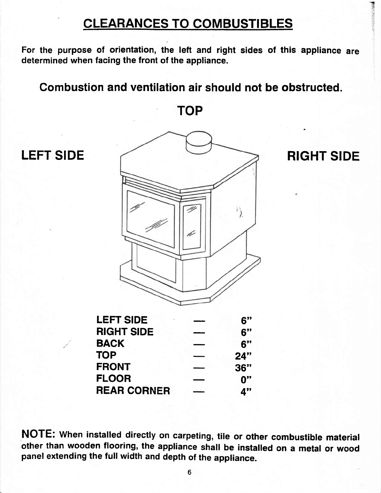
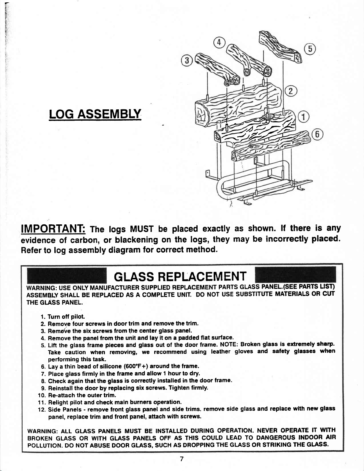


 Loading...