

Page 1
OWNERS
MANUAL
GENTURY
VENTED
GAS
WARNING:
not
result causing
or loss
-
Do not
ftammable
vicinity
-WHAT
.
.
.
.
.
G400
FIREPLAGE
the
lf
life
store
of
TO
try
not
touch
not
not
cannot
the
exactly,
property
vapors
this
DO
to
use
instructions.
fire
followed
of
Do
Do
Do
lmmediately
neighbor's
a
supplier's
ydu
lf
call
HEATING
information
fire
a
use
or
or any
IF
light
any electrical
phone
any
your
call
Phone.
reach
dePartment.
in this
or explosion
damage,
gasoline
liquids
and
other
YOU
aPPliance.
any
in
gas
Follow
your
manual
personal iniury
or
in
appliance-
SMELL
switch.
your
gjas
building.
supplier
the
supplier,
is
may
other
the
GAS
from
gas
HEATER
-
INSTALLATION
MUST
A
QUALIFIED
SERVICE
THE
"WARNTNG:"
MAINTENANCE OqN CNUSE
tNFoRMATtox
ADDITIONAL
OR GAS
made
CANADA
labriqu6
au CANAOA
SUPPLIER.
in
IMPROPER
unuuAL
INFORMATION
|NSTALUTTON,
pRovtDED
AND
PERFORMED
BE
SERVIGE
INSTALLER,
AGENCY
GAS
NJURY
CONSTJLT A QIJALIFIED
NOTES:
MUST
iHEnpplnNcE
OFF.
SUPPLIER
ADJTJSTMENT
OR PROPERTY
wtrH
THIS IS A SEALED
ALWAYS
ANY
SAVE
THts
BE INSTALLED
wlTH
LEAKAGE MAY
THIS
OR
DAMAGE.
AppLtANcE
INSTALLER,
APPLIANCE
BROKEN
CAUSE
MAI'IUAL
BV
ALTERNION,
REFER
Ass/srAwcE
FoR
SERVICE
AND
DURING
GLASS
F()R
OPERATION.
wlTH
OR
DANGEROUS
FUTURE
SERV,CE
THE
TO
GLASS
THE
NEVER
GLASS
THE
POLLUTION.
AIR
OR
OWNER'S
FoR
oR
AGENCV
RETAINER
OPERATE
RETAINER
REFERET'ICE
Part No.
519402
Rev.3 08/99
PRINTED
IN CANAOA
Page 2
,rrr2
S
CENTURY
HEATING
INSTALLATION
PLEAilEREADTHTIMANUALBEF1RETNiTALLINGAND|JStNGYoUnyENTEDGAS
FIREPLACE
FOR
Do
otner
in the
appliance.
FOR
lf
1.
2.
3.
-
YOUB
store
not
flammable
vlcinitY
YOUR
you
smell
not
Do
nol
Do
nqt
do
tMIuiEDnrELY
cAC
phone.
instructions.
iit6u
4.
the
cail
AND
HEATER
SAFETY
or
of
gas:
to
try
touch
any
use
SuPPLIER
Follow
cannol
dePartment.
lire
OPERATION
gasoline
use
or
and
any
vaPorc
this
SAFETY
applianc.e'.
any
light
electrical
any
phone in
CALL
lrom
gas
the
reach
suPPlier's
your
switcn;
the
YOqR
neighbor's
gas
INSTHUCTIONS
or
liquids
other
buildlng'
supplier'
HIGH
TO
DUE
APPLIANCE
THE
UOCITEO
NWNV
DRAPERIES.
NOT
DO
oinen
ON
OT.T
ciiruoneN
AtEtrTED
B-E
iiloH
oF
NTIO
IVbrO
IGNITION.
OUT
FROM
PLACE
FLAMMABLE
NEAR
AND
suRFAcE
STTOULD
BURNS
TEMPERATURES'
SHOULD
TRAFFIC
OF
FURNITURE
CLOTHING
BE
AND
AND
OR
MATERI4L
APPLIANCE.
THE
ADULTS
THE
TO
sHo-uLD
HAZARDS-
TEMPERATURE
STAY
OR
AWAY
CLOTHING
TO
.
WARNING:
IMPROPER
MATNTENANCE
MANUAL
tNsTALLEn,
INSTALLATION,
CAUSE
cAN
AsstsrANcE
FoR
seiv'ibe'-leEnrcv
#from$S*r.'oNscA'Frql!:Y-.gElgLF-ss1st$fl1*x1'?Irifl b'ft
FoLLow
To
WILL
VOID
PTEASE
rHEsE
THE
RETAIN
rNsrRucrro'r'rs
WARRANTY.
IH'S
ADJUSTMENT,
llJgiv-bc
ql
lpq'.i.iolli $r^*MlilitN
THE
oR
laM
MANITAL
FOR
AUTERATION'
pnopEryrv'oni,rnce-
SUPPLIER'
GAS
nesur-frN;
FIJTITRE
REFERENCE'
SERVICE
coNsuLr
FilisreLE
OR
!FfER
F.RE
rHrs
ro
QUALTFIED
A
HAZARD
AND
-_.=*<4!:q|I
Page 3
1 (800) 668-5323
Monday to Friday, 9am to 5pm Eastern Standard time
Page 4
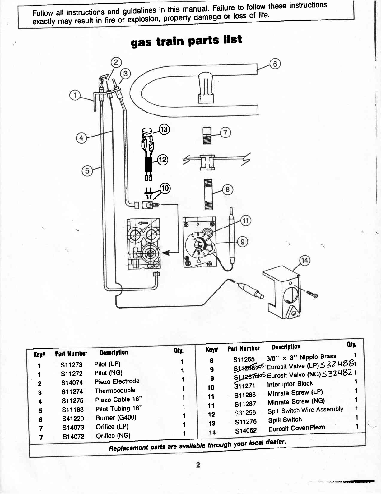
ffinsandguide|inesinthismanua|.Fai|ureto|o||owtheseinstructions
exactly
may
resuliifri?i
"i
gas train
F
VP
Parts
list
K.Vt
1
1
2
3
4
5
6
7
7
ttttfi
P.tt
S11273
511272
514074
511274
511275
511183
S41220
S14073
514072
DercrlPtlon
(LP)
Pilot
(NG)
Pilot
Electrode
Piezo
ThermocouPle
Cable
Piezo
Tubing
Pilot
Burner
Orifice
Orifice
ReplacemeHt
16"
16"
(G4OO)
(LP)
(NG)
parts
","
0tY'
1
1
1
1
1
1
1
"*t''"
ffisdptlon
8
;
S11265,
Z)iaw
; {tiJ*"eurosit
to
11
11
12
1
1
13
"""t^
{rtr,
511288
511287
s31258
s11276
S14062
""''t*'
3/8"
l'l'o'it
varve'(LP)s
Valve
InteruPtor
Minrate
Minrate
spill
:l1l^:_T:: a,rPiano I
Eurosit
Block
Screw
Screw
switch
CIYIP|"*
wire
NiPPle
3"
x
Brass
?2
(NG)532t182
(LP)
(NG)
Assembly
ri.r.iiffrdltflFi.:
1
u98t
1
1
1
1
1
otv'
Page 5
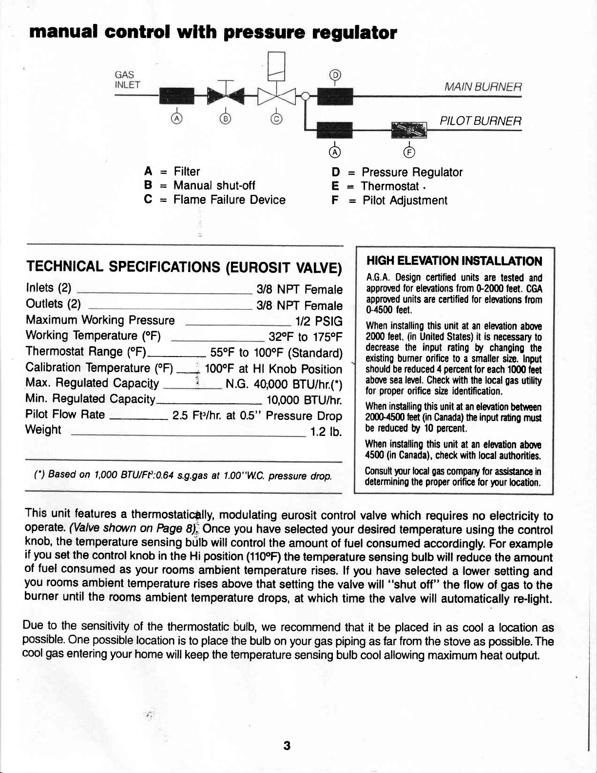
manual
control
wlth
pressure
regulator
6
I
,/A
(r.i
PILOT BUHNER
TECHNTCAL
Inlets
Outlets
Maximum
Working
Thermostat
Calibration
Max.
Min.
Pilot
(2)
(2)
Temperature
Regulated
Regulated
Flow
SPEC|FICAT|ONS
Working
Range
Temperature (oF)
Capacily
Capacity-
Rate
-
Weight
(')
Based
on 1,000
A=
B=
Q=
Pressure
(oF)
fF)--
BTU/Ff
:0.64
Filter
Manual
Flame
shut-off
Failure
(EUROS|T
55oF to IOOoF
100oF
,
N.G.
2.5 Ft./hr. at
s.g.gas
at 1.00"W.C.
Device
VALVE)
3/8 NPT
3/8 NPT
32oF
at
Hl Knob
4q,000
1o,ooo
0.S" Pressure
pressure
Female
Female
1/2
PSIG
to 175oF
(Standard)
position
BTU/hr.(')
BTU/hr.
'1.2lb.
drop.
D = Pressure Regulator
E = Thermostat.
F = Pilot Adjustment
HIGH ELEVATION
Drop
A.G.A. Oesign
approved
approved
G4500 feet.
When installing
feet,
2000
decrease the input
existing burner
should be reduced
aborc
sea
proper
for
When installing
2000-4500leet
be reduced
When installing
(in
45fi)
your
Consuh
determining
certified
for
elaations
unils are
this unit at an
(in
United
orifice t0 a smaller
4
la/el.
Check with
orifice size identification.
this unit at
(in
Canada)
percent.
by 10
this unit at
Canada),
local
proper
the
check with
gas
INSTALLANON
units are
from
0-2000 feet.
certified
lor
elaations from
elention
it is
States)
nting by
percent
for
local
the
an elaation
input
$e
an elantion
local authorities.
company lor
orifice lor
changing
each 1ffi0leel
your
tested and
CM
above
necessary
size. lnput
nting
asigance in
to
the
gas
utility
betneen
mug
abon
location.
This
unit
operate.
knob,
you
if
of fuel
you
burner
Due
possible.
coolgas
(Valve
the
set
consumed
rooms
until
to
the
One
entering
features
temperature
the
ambient
a thermostaticilly,
shovrn
on
sensing
control
knob
as
your
temperature
the rooms
sensitivity
possible
your
of the
location
home
modulating
hge
SI; Once
O0tO
in
the Hi
rooms
will controlthe
position
ambient temperature
rises above
ambient
temperature
thermostatic bulb, we
place
is to
will keep
temperature
the
you
(110'R
the
bulb
eurosit control
have
selected
amount
the temperature
rises.
that
setting the valve
drops,
at which
recommend
your gas piping
on
sensing bulb cool allowing
3
valve which requires
your
desired temperature
of fuel consumed
accordingly. For
sensing butb
you
lf
have
will
selected a lower
"shut
off" the flow
time the valve will
placed
it
that
be
far from
as
the stove
no
electricity
using
the control
example
will reduce
the amount
setting
gas
of
to
and
the
automatically re-light.
in
as
cool a
location
possible.The
as
maximum heat output.
to
as
Page 6
---\
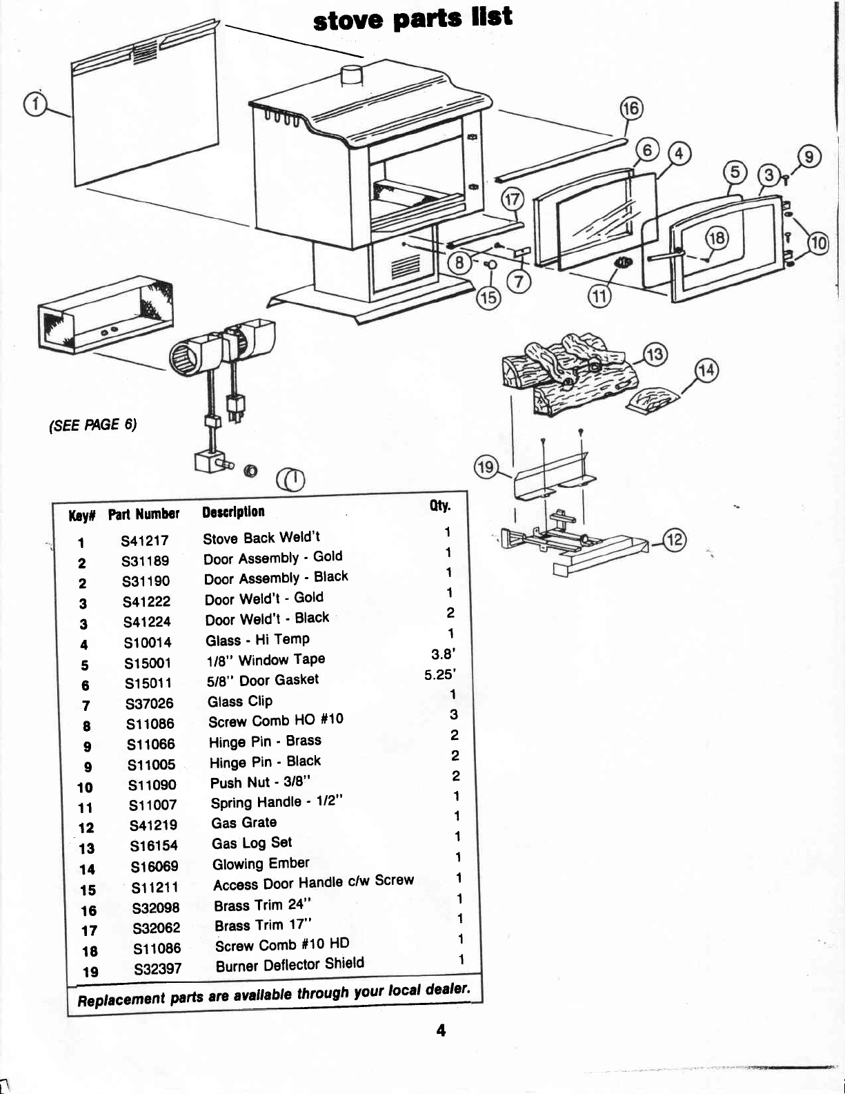
stove
Parts
llst
(sEE PAGE
Part
Koy#
I
2
10
11
S41217
S31189
2
3
3
4
12
13
14
S31190
5
6
7
I
I
9
15
16
17
18
19
Replacement
6)
llumbcr
541222
541224
S1OO14
S15001
S15011
S37026
S11086
S11066
S110O5
S11O9O
S11007
S41219
S16154
516069
S11211
S32098
532062
S11086
S32397
parts
Dorcdptlon
Weld't
Stove
Back
AssemblY
Door
AssemblY
Door
Weld't'
Door
DoorWeld't'
Glass'Hi
1/8"
5/8"
Glass
Screw
Hinge
Hinge
Push
SPring
Gas
Gas
Glowing
Access
Brass
Brass
Screw
Burner
arc
TemP
Window
Gasket
Door
GliP
Comb
Pin'
Pin'
Nut'3/8"
Handle
Grate
Set
Log
Ember
Door
Trim
Trim
Comb
Deflector
avattable
'
Gold
'
Black
Gold
Black
TaPe
#10
HO
Brass
Black
'112"
Handle
24"
17"
#10
through
c/w
HD
Shield
lour
Screw
local
otv.
1
1
1
1
2
1
3.8'
5.25'
1
3
2
2
2
1
1
1
1
1
1
1
1
1
dealer'
11
t\
4
Page 7

ANY
SAFETY
REPLACED
PRIOR
SCREEN
OR
TO
OPERATING
GUARD
REMOVED
THE
FOR
SERVICING
APPLIANCE.
AN
APPLIANCE
MUST
BE
''WARNING''
CRACKED
LICENSED
YOUNG
SAME
door
REMOVE
BE
set
CHILDREN
ROOM
lock
SURE
assembly
DO
NOT
OPERATE
OR BROKEN.
OR
QUALIFIED
SHOULD
AS
THE
APPLIANCE.
screw
DOOR
TO
LOCK
REPLACE
THE
APPLIANCE
REPLACEMENT
SERVICE
BE
SCREW
AFTER
BEFORE
SERVTCING
PERSON.
CAREFULLY
WITH
OFTHE
SUPERVISED
ATTEMPTING
TO
AVOID
THE
GLASS
TO
ACCIDENTAL
GLASS FRONT
SHOUT
WHEN
OPEN DOOR.
D BE DONE
THEY AHE
OPENING
-8.>C/:
REMOVED,
BY
A
IN
THE
OF DOOR.
mlneral
Remove
suppfied.
S4".
log
HUTION:
UNDER
"TOO
USE
RE-INSTALL
BEFORE
UUT,ON;
OF BURNEN
, rszlr,r.rwc
a handfulof
Break
Loosely
tray
grate
of
BURNER
ilUCH"
ONLY IN
OPERATING
and
DO
EIVSURE
wool
placement
mineralwoolfrom
pieces
into
evenly
as
shorn
NOI
PACK
DO
WOOL.
LOCATION
DOOR
'GA"TES
LOCK
FRONT
wooL.
roughly
place
wool
above.
WOOL
NOT
USE
SPECIFIED.
SCREW
UNIT.
PORT/ION
AFIER
bag
314',
x
in front
Page 8

FIG.
A
-a
-------->
fan
1.
2.
'
lnstallatlon
Remove
Using
Be
Speed
3.
and
Snap
4.
Plug
5.
Elcblcrl
This appliance
throeprong
protsction
your
hazard
directly
threeprong
not cut
Do
prong
ding
fan
four
to
sure
control
tighten
variable
in.
fan
illlxo
w
Goundl4
b €quiPPed
(grcunding)
should
and
a
inlo
Pfoporly
receBeclo.
or tamwe
lrom this
from
screws
install
switch
secure.
until
speed
Inrtucllonr
wilh
Plug
againsl
shock
be
Plugged
grounded
groun'
the
Plug'
instructlons
carton.
provided
rubber
is
control
a
for
attach
gromets as
inserted
be
to
knob
fan.to
shown
into
FAN
LINE
1lOV
stove
as
above'
pedestal, as
into
place'
W|/NING
D/,AGNAM
(ipttonal
shown
above'
shown,
fan
VARIABLE
CONTROL
klt
CAUIfOX
to
Drlor
tcnlcttrg
ciure
c.n
d.ngarous
"WrW
canlclng;'
W.
G.
B.
#S3rr92l
"bbcl
-
dlrconnrcllon
conlrolf.
oPenllon."
NoPat
FAN
11OV
SPEED
tll
ffirltry
lmProPcr
oPe/lllton
MOTOR
60Hz
wlnt
whcn
ormn
tnd
.lLl
1.5
AMP
l(cy#
1
2
3
4
5
llumbor
Parl
541225
S41059
S14003
S140OS
S140Og
Ducrlpllon
Case
Fan
AssY
Motor
SPeed
Power
Speed
Control
Cord
Control
Weld't'G40O
-
G300
Switch
Knob
0ty'
1
1
1
1
1
@
6
@-"
Page 9

CIOTHING
NEAR
OR
OTHER
THE APPLIANCE.
installation
GAS
Manifold Pressure
Minimum Inlet Pressure'
Maximum lnlet
Fl'U Input
Input
BTU
gas
Make
2.
l) Black iron
ll) A corrugated
in
length)
lll)
Copper
table to the authority
gas
Turn
OPEN FLAME.
For correct
ASSEMBLY.
lnstallation and
tion air must
local
of
Z,223|l - latest
Canada, with
Code.
codes,
Pressure
(Max.)
Rating
(Min.)
Rating
'For
purpose
connection
pipe
metal
. .
or
pipe
or tubing
supply
on and
Use soap and
positioning
provision
conlorm
with
edition - in
the
current CAN/CGA
FLAMMABLE
instructions
SPECIFICATIONS
llatural
ot lnput
to
the
or malleable
connector
.
(internally
having
check for leaks. DO NOf
of logs
for
with local
the National
the
Gas
3.5" W.C.
5.0" w.c.
10.5"
W.C.
30,000
23,500
Mustment.
valve
assembly
iron fittings or . .
(not
to exceed 2
tinned)
jurisdiction.
water solution.
grate,
on the
combustion
codes o[ in absence
Fuel Gas Code, ANSI
United States
-
Bl49.lnstallation
MATER'AIS
Propane/LP
10.0" w.c.
WC.
11.0"
13.0" W.C.
26,000
23,500
with:
.
feet
if
accep-
USE
refer to
and
SET
ventila-
or, in
SHOULD NOT
Keep operating area
materials,
vapours.
The appliance and
disconnected from the
any
excess
8.
The
ing
by
ing
any
at test
9.
A 1/8" inch
gauge
upstream
gas
A
llue
DUE
TO HIGH TEMPERATURES,
SHOULD
AWAY
The
appliance,
connected
codes or, in
current
the National
gasoline,
pressure
1/2
of
appliance
closing its individual
pressure
pressure
N.Hl-.
connection
of the
appliance must
serving
FROM FURNITURE
C9{ C22-1
a soparate
BE LOCATED OUT
and
the absence
Electrical
BE PLACED
and
clear
and other
individual
its
gas
supply
system at test
testing
when installed
grounded
of the
psig (3.5
musl be
testing
equalto
gas
kPa.)
isolated
of the
less than
or
plugged
supply connection
Canadian
code ANSI/NFPA
tapping,
must be
not be connected
solid
AND DBAPERIES.
in accordance
local
of
Electric C'ode
manual
OR
O'V
free lrom combustible
llammable
shut off
piping
from the
shut
gas
supply
accessible for
provided
fuel burning appliance.
THE APPLIANCE
OF TRAFFIC AND
must
be
codes,
liquids
valve
system during
pressures
gas
supply
otf
piping
psig
112
immediately
to the appliance.
to
electrically
with local
with
(Canada)
TGlatest
and
must be
pip
valve
dur-
systom
(35
kPa.).
test
a chimney
the
or
edition
in
CH'LDREN
TEMPENNURE
CLEARANCE
Ceiling
Sides
Front
Back
please
It
is
normalfor your
This
Please
IT
BE
ADEOI'ATE
SERI/ICE
DIRECT
Height
of Stove
note
is
due
to the curing
ensure
IS
IMPEBATIVE
KEPT
that
CLEAN
CLEARANCES
AND PROPER
VENT
AND ADULTS
AND
SHOUTD
TO
COMBUSTIBLES
Century
your
THAT
AND
TERi'INATION
Heating fireplace
paint
of the
room is wellventllatqd
THE CONTROL
CLEAR.
AROUND AIR OPENINGS
OPERATTON. NEVER
SHOUTD
Minimum = 24"
Minimum
Minimum = 36"
Minimum
and
PROVTDE FOR
THE EXTERIOR
ON
BE ALERTED
AWAY TO
STAY
=
=
any undetected
COMPARITUENT
TO
AVOID
DO NOT
lhe fieater
8"
9"
give
to
-
OBSTRUCT THE
otf some odour the first tlme
open
atlwindows.
ADEOUATE
OF THE
whlch
from
oll
BURNER, AND CTRCULATING AIB PASSAGE
COMBUSTION
AND
BUILDING.
THE HATARDS OF HIGH SURFACE
BUR'VS
been under
qualtfled
control
OR CI.OTHING
lfits heater
USE
water. lmmedlately call a
serylce
and
system and
technlclan to
to replace any
any
has been under
it is burned.
the manufacturing
AND VENTILATION AIR.
ADEOUATE ACCESSIBILITY
FRONT
OPENING OF THE
process.
'G'V'T'O'V.
lf any
paft
inspect
part
gas
control
waten
CLEARANCE
APPLTANCE OR
has
of the
WAYS
PROVIDE
FOR
THE
7
Page 10

temperature
(#1
The thermostat
see berow
range
drawing)
caribrated
is
and
set
at
factory'
the
(55-110"F)
gas
Maximum
the
Minimum
the
This
rate
This
flow
knob
knob
(#4 see
flow
(#4 see
rate
flow
screw).
screw
flow
rate
is
(#3
rate
pressure
pressure
tnret
turns
3
2 or
Oulet
pressure can
WARN'NG;
SCREWs
can
and
AFTER
cLOcKwGi
checked
be
can
below
can
berow
determined
see
drawing)
be checked
drawing)
by
below
drawing)
readings
checked
be
placing tubing
then
be checled
TAKING
rrnnrLY
cooling
by
counter
by
counter
o.E.M.
the
must
turning
by
[he
in
PRESSURE
TO
clockwise
cooling
crockwise
at
be
captured
gauge
to
same
RESEAL.
Adiushent
Pilot
thermostat
the
the
to
thermostatic
the
$;rt
design
the
driven
over
manner
READINGS,
Screw
rt"i"
fully
screw
test
NOT
DO
above
below
bulb
position'
Hl
below
bulb
rtopping
"no
seiwitfr
and
assure
down
point'
to
(#6 see
BE
OVER
drawing
using
SURE_I9JIJRN
captured
ToROUE'
temperature
room
temperature
room
when
a
proper
you hear
pre-drilled
below)
screw
CAPTURED
screw
flow'
counter
(#7)'
turning
and
turning
and
"snap"'
the
(minimum
clockwise
Minimun
Regulalor
Pressure
WARN'NG;
FLow,
cAs
H,i
8ffi
GAS
THE
ANy
rooLs
THE
CONTROL
Rate Screw
i
Iemperalure
rHE
r'rt=*ii
Sensing
CONTROL
ptLor
"'*'
KNOB
DURTNG
Bulb
AN
HAS
BURNER
HH;
E
i,il
DESIGNED
IS
rHrs
opERAiiNG.
INTERLOCK
crnHor
iil\c
BE
Ei
N
TO
DAMAG'6-ftrloes
Pressure
0ullel
Pornt
Test
Plessure
lnlel
Poinl
Iesl
DEVICE;
RELri
e e
io
BE-OPERATED
AFTER
rli,r^::t^ Tlt^T*t:3:::i
''
e
n
r
e
s
BY
MAY
SHUTTING
p
p
rox.
(
a
D
HAND'
DO
RESULT
OFF
t-
:
.:::' I .
ilOT
sERlous
lN
ALL
to'
USE
Page 11

yentlng
Instaltailon
guldeflnes
PROPER
IS
AN
IMPORTANT
APPLIANCE
IF
YOU
ATTEMPT
GAS
APPLIANCES,
flsted
A
designed,
combustion,
burning
,"_"1!,9T?l_oy
rng
warm
lype
gas
listed
and
fuel
atr
space.
and reduce
B
lllsted
Irfgl"
and
!1q
mrnrmum
obstruction
fla!
the
.of the.
Gas
beginning
Gas
Vent
vents.
rools
are
roof
and
bu.itdi
Vent.
extending
height
wirhin
requiredr6
at
ng
INSTALLATION
SAFETY
PERFOFMANCE
ARE
NOT
QUALIFIED,
INSTALLATIONS
PIPTNG
vents
vent
is
a
instalted
excess
gas.
metal
doubte
wail
This
air.spac-e
heat
vent
B.O
instailation
size
conform
of
at
3m
least
60O
or
adjolnin
factory
exctusively
airi
vents,
construction
transferred
or
through pitcnJi
lea.st
(10').
exireno
mm
g
made
and
diiution
me
both
instalfa$on
G]€aterf
be
sure
to
building
g0O
g,
cas
venti-dxrenoing
"tliili
(2')
frigfrerinan
Oujrainglvitfrin'gm
OF
GAS
VENTING
AND
CONCERN.
DO
NOT
Oi
NCPNIRS
OR
VENTING.
and
listed
toi
iemoving p.Oj"tJoi
air
reiutting
moslcommon
enclosing
helps
to
niarOy
that
coJe
i*f,
(2')
6db',rn
the
an
keep-flue
cbmbusiibles.
overail
requiremen-tr.
."n
higher
iz,)
any
O,i
tr
OF
system
tro;
type
iniufat_
gases
height
exrend
than
any
ihiiugf,
aooie
portion
oi
if,"
of
a
TYPICAL
and
Awey
Out
EnClosure
Gas Vent
"B''
VENT
Keep
Eleclricit
Buitdrnq
From
Gis
The
Ol
Reeurrcd
Wall
Length
25 mm
fl'l
Clearance
Combustrbtcs
IT{STALLATION
wires
Insutalron
Vcnt
rnd
Art
Sorc:
Fo
F
rrgglgp
Spacer
suDport Ptata
Where
8pace3,
cortact
l1re Taung- 9Qual
tnrough
alnglc
Sltuate
be
malortoad
tmportant
n9l
I}1,_rl"^,.app[ance
carpeung,.ille
than
es
wldth
thc
Gas
lt
should
and
whtch
or
two-hmily
the
Inctatted
Gas
beqtng
to
posslbte
as
wood
f toortng,
on
a
metat
and
depth
vent
be
damage.
to
the
Vent
ln
wtrhour
cutilnj
partrtroni'oi;;i#;.
locete
or
the
to
the
other
ttra
or wood
of
the
cxtonds
cncloseO
through
to
iod
Enclosurr,"afli
grcater
or
Gas.%nt
dwelllngr.
the
atructure
base
heailng
is
Instailed
combusilble
than
pasc--
i"t.6;;iltr,
of
the
appltance.
materlal
ippr[nce;;jil"
panel
extendlng
ippflance.
accegslble
pereonal
"froufd
thc
ftoore
-xcept
so that
lt
ptates
I te
Gas
Vent
dtrecili
bther
Instath
the
hare
In
can
or
atso
as
on
full
Thls
appllance
syst?m
deslgned
ventlng
THIS
APPLIANCE
A
CHIMNEY
FUEL
BURNING
Use
only
above
Consult
the conect
than
the
necessary
ls
equlpped
to
of
combustion
MUST
FI.UE
SERYING
APPLIANCE
vents
the
labelled
roofllne.
Authorlty
Gas
\tentiilametJr.
yent
wlth
protect
products.
NOT
BE
A
'.FOR
havlng
diameter.
furlsdlcilon
eroic
Adtustable
agalnst
CONNECTED
SEPARATE
EXTERIOR
a
sahty
;t;i
Length
contrcl
lmproper
SOLID
USE',
lo
setect
a
targer
TO
',:j
.ii
il
1
.rj
lrl
:!l
i'i{
iii
Ilr
ti,
!i
fj
Ji:i
li
I
I
I
i
,
Page 12

venting
installation
guldellnes
WARN'NG!
Installations
procedures
iools
and
Installations
peron
io the
to the
Installer,
should
required for the
testing
made
risk of injury
installatlon
be
only
instruments,
be unqualiiied
or
but also to
persons
llisted
qualilied
and
by
ol
who
made
Installation
persons
electrlcat
shock
being
B.O
Yentl
the
have athleved
can
serued
persons
Product'
result
whlch
by
continued
CHECKING
gas
Complete
and
adiusting
lighting
couple
lighted
a
of the
ing(s).
flame toward
ilamg
lmproper
escape
will
be
-l
I
I
I
i
The dratt
same
tion
all
vent connections.
the
the main
ol
minutss
match
gralt
draft
of the
oI Ing
Proper
lowaro
cause
pulled
venting
or
or
venting,
or sPillage
match
into
the
hood
atmosphiiic
Inlet
air
who
equipped
arc
who
Proper.certificatlon
hazards
In
be
can
equlpment.
the
VENT
piping, electrical,
appliance(s)
burner(s),
forwarm'up.
under
iust
into
lnto
hood
lllJu(J
willdraw
the
InGt
indicated
burned
of
flicker
to
draft
must
relief
lElrer
sublectlng
serious
or
CAPACITY
After
and
a
allow
Hold
rim
the
op€n-
vPerr-
the
u'
hood.
rr|",t
draft
ulalt
bY
gas'
go
or
hood
be
smoke
out.
vent
if the
lfrstalled
pressure
aPPllance.
the
to
famillar
are
wlth the safety
wlth the
licensing.
of
unqualified
the
fatal not only
even
-: .,'
.(
../ |
.r'
is
zone
|
| Y
il .. *'oI Ine
ll
V'
a cigarette
from
drawing
to
as
so
the
as
proper
..
\
-.
\
k)-.
-\ -
T
\
will also
properly'
in the
be
combus'
.\
)
\
When
your vent
iemperature
clearances
ed.
jurisdiction in
venting
venting
PiPe
rating.
must
Consult
through
through
have
must
Manulacturer's
be
also
authoritY
the
your
area
wall.
side
a side
wall
the
ProPer
maintain'
having
regarding
10
il
{xi
Page 13

WARNING!
Installations
procedures
tools
and
Installations
person
to
the
instafler,
testing
to
the
required
made
venting
should
risk
only
for
instruments,
be
of
lnirty
but
also
installation
be
made
the
installation
and
unqualified
or
electrical
persons
to
qualified
by
of
who
have
persons
shock
being
guidelines
persons
product,
the
achieved proper
can
result
which
served
in-hazards
can
by
the
who
are familiar
who
are
equipped
certificaiion
sublecting
be
serious
equipment.
with
with
of
the
or evin
the
salety
proper
the
licensing.
unqualified
latat
not
only
chimneys
o
Complete
clearance
Consult
area
applicalions.
A
complete
persons
o
Appliances
masonry
feet
vent
connector
.
Oversized
listed
r
Cleanout
familiarity
to
combustibles
the
authorlty
regarding
chimney
should
using
or factory-built
in
length
for
connector
has
chirnneyd
relining
systems.
access
relining
Suitability
determined.
Condition,
relined
a
No
a
Joints
manufacturer's
and
size,
must
be
substitution
and
connectors
with
chimney
and
having
masonry
inspection
performed.
be
B
vent
connectors
chimney
every
inch
of connector
has
a maximum
maximum
may
7-112
should
be relined
be required.
systems
approval
height,
determined.
instructions.
of relining
termination
of
components
should
condition,
other
lactors
jurisdiction
chimney
made
by
to vent
should
4-ll?tdot
foot
be
not
diameter (3
length;
length).
with
materials
of
the
chimney
should
made
according
height,
is
venting
qualified
exceed
bppropriate
be
size,
essential.
your
in
into
1-1/2
inch
inch
5
should
be
to
be
made.
to
a
installation
STRAIGHT
INSTALLATION
INTO
CHIMNEY
installation
TYPICAL
STRAIGHT
INSTALLATION
MASONRY
gitt"ffiii"y
Liner)
I
l,
;i
ri
Consult
area
applications.
OPERATION
AND
COULD
PROPERTY,
F- rr
rollow
result
the
authority
regarding
OF
MAINTAINED
RESULT
DAMAGE
Instructions
all
in
fire
or
having
listed
lurlsdiction
chimney
IMPROPERLY
VENTING
IN
SERIOUS
OR
LOSS
guidelines
and
explosion,
property
your
in
liner
venting
INSTALLED
SYSTEM
INJURY,
OF LIFE.
in this
damage
manual.
or
Failure
loss
of life.
to follow
these
instructions
exactly may
Page 14

ErrttrNvs
flltrlN
I
INSTr|UGTIONS
Periodic
1.
lo ensure that the
valve control knob
All component
3.
manufacturer. Write
visual checks
flame
is
GAS
CONTROL
parts
Century Heating
Humberline Drive,
330
Ontario, Canada, MgW 1R5
1-800-836-1210 United States
1-416-798-2800 Canada
pilot
of the
is
in
the
are available directly
phone.
or
Etobicoke
should
present
"OFF"
be
excgpt
position.
TYPICAL
AURNER
Line
Watts
through
conducted
when the
-
FLAME
(A)
AND CARRY
the
Periodically
2.
vacuum
and
burner areas.
PATTERN SHOWING
DOWN POFTS
installation
qualified
inspected
quititiea
control
passageway's of
ireque-nt
lint from
sivd
5. Disconnect
remove
any
and
service
before
service
compartments,
clianing
all
logs
the
particles
loose
(B)
carpeting,
power
VIEW
repairs
all
person. The
and
use
person. lt is
burners
appliance
the
be
may
to unit
from the
from the
PILOT
OF
FROM
should
appliance
least
at
and
be
required
bedding
before
grate
assembly
grate
FLAME
ABOVE
be done
should
annually
imperative
circulatin-g
clean.
kgpJ
due.to
material
servicing'
etc.
and
by a
be
by a
that
air
More
exces'
WARiltNG:
DO
COMBUSTIBLE
inspection
-
Pilot and main
-
Check
-
Venting should
cleaning
(Dlsconnect
1. Remove
2. Using
3. Cleai
using
4. Re-install
and clean
of
all
burner
vacuum, clean
a
burner
small wire
a
burner
NOr ADJUST
MATERIALS,
burner
be
flames
main
the
checked
burner
main
power
hold down
parts
using
or
and
gas
and
bottom
vacuum
paperclip. Ensure
burner
THE GAS
GASOLINE
should
be
once
year
once
a
burner
supply
screws
of
deflector
to fhe unit).
and
firebox
any
and
and
ORIFICE.
KEEP.AREA
AND OTHER
checked
year.
a
assure
to
and
remove
and
particals
that all
put
visually
proper
orifice
burner and
orifice.
that may
parts
logs in their
CLEAR
FLAMMABLE
each
VAPOURS
month.
functioning.
burner
be
are free
proper
deflector
lodged
debris.
from
location.
AND
ports
in
FREE
AND
shield.
to
are
FROM
LIQUIDS.
removed
be
12
Page 15

IF
YOU
MAY
This
lighting
b.
BEFORE
area for
because
on the floor.
WHAT
o
Do
r
Do not
phone
r
lmmediately
neighbour's
Follow
o
you
lf
fire
DO
NOT
RESULT
appliance
the
LIGHTING
gas.
some
TO
not try
touch
in
the
cannot reach
department.
CAUSING
has
pilot,
follow
Be
sure
gas
OO IF
your
YOU
to light
any
building.
call
phone.
gas
supplier's
F('r| V('U]|
BEAD BEFORE
FOLLOW
piezo
a
these
smellatlaround
to
smell next
is
heavier
SMELL
any
appliance.
electrical
your gas
your
THESE
PROPERIY
ignition
instructions
than air
GAS
switch;
supplier
instructions.
gas
supplier, call
INSTRUCTIONS
DAMAGE,
pilot.
When
exacily.
the
apptiance
to the floor
will
and
do not use
from
setile
a
SAFETY
LIGHTING
WARNING:
PERSONAL
d.
any
the
EXACTLY
Use only
control
push
qualified
a
repair
Do
under
technician
any
which
your
knob. Never use tools. lf
in
or turn
service
may result
not
use
water.
to inspect the appliance
part
of the control system
has
been under
A FIRE
EXPLOSION
OR
INJURY OR LOSS
hand to
by hand,
this appliance if
lmmediately call a
push
in
or turn
the
don't try to
technician. Force
in
a fire
or explosion.
part
any
qualified
and any
water.
OF LIFE.
the
knob will
repair
it,
or
attempted
has
service
and
to replace
gas
control
gas
not
call
been
-
1.
STOP!
2. Push
in
Wait
five
then
smell
information.
Read
tfre
gas
control knob
"OFF".
lo
(5)
minutes
gas,
you
lf
LIGHTING
safety information.
slightly and
to
clear
out any
STOP! Follow
don't smell
"8"
gas, go
TNSTRUCIIONS
turn clockwise
gas.
in
to next
you
lf
the saiety
step.
4.
5.
6.
pilot.
Find
Turn
knob
"PILOT".
to
Push
in
lmmediately
hold
the
after
the
back
up. Pilot
repeat
r
lf knob
immediately
supplier.
.
lf the
the
service
r
Disconect
gas
Turn
"ON".
to
gas
on
control knob
control knob in for
pilot
steps
does not
pilot
gas
control
technician or
control knob
control counter-clockwise
all the way
light the
is lit. Release
5 through
call
will not stay lit
all
pilot
should remain
pop
your
knob
power
-
r-
and hold
with ignitor,
approx.
knob
lit. lf it
L
when released,
up
service
to
gas
source
counter-clockwise
technician
after
several tries,
"OFF"
supplier.
to the
in.
Continue
(2)
minutes
it
and
and
unit,
will
goes
stop
call
r-.
or
to
pop
out,
and
gas
turn
your
-TO
1.
Push
/-:r
in
gas
to
control
knob
"OFF".
TUI|N
slightly
Do
not force.
('FF
and turn
GAS
clockwise
T(,APPLIANGE-
Page 16

-
T}Io)UBLE
SHOOTTNG.
G4OO
proper
With
tree
dervice.
guide
will assiit a
action
l. Spark
repeated triggerlng
after
red
button.
instailation
to be taken.
SYMPTOM
tgnitor
you
lf
do
qualiiied
will not light
and
maintenance,
experience a
servic'e
A.
of
at
B.
electrode
electrode).
your
problem,
persion
POSSIBLE
Defective
electrode).
Delective
at
gas
No
c.
new Gas
to the
refer
the diagnosis
in
CAUSE
(no
lgnitor
pilot
pitot (spark
low
or
spark
misaligned
or
at
pressure.
gas
'
Fireplace
trouble
should
shooting-
of
-
'
provide
guide
problems
CORRECTIVE
1. Check
pilot;
and
is
wire
replace
Using
1.
lights,
button
red
imProPer
an
caused
a
and
recommended.
light'check
and
Pilot'
a strong
have
OK,
lf
check
1.
fireplace.
lrom
valve
sometimes
main.
the
(1)
one
main'
and
shown
and
for
if no
properly connecled,
ignitor.
match,
a
otf
turn
again.
gas/air
imProPer
the
longer
rePlace
near
should
remote
the
there
There
valve
Purge
gap
between
yeaq
of troubl+
below. This
correctlve
the
ACTION
at electrode
spark
and electrode
spark
pilot'
light
pilot-and
pilot
lf
mixture
lighting
Period
lf
sPark'
Pilot'
Usually
firePlace
will
Pilot
electrode
at
be 1/8
shut
valve near
is a
be
can
the
there
pilot
lf
trigger the
lights,
is
not
inch
to
off valves
is
a
and
more than
fireplace
will not
Pilot
ll.
caretully
Instructions.
following lighting
stay
lit after
L.P. in tank.
No
D.
A. Defective
B Defective
Plugged burner
C.
valve.
thermocouple.
orifice.
pressure
Low
2.
variety
a
bent
pipe
Check
consult
supplier.
1.
be out
1.
on
adjust
impingement
1. Replace
field
1. Check
page
of situatlons
narrow
too
line,
low
even
or
lor kinked
with
Plumber
Check
Check
thermocouPle.
L.P.
fuel.
of
pilot
pilot
for
on
valve
serviceable).
burner
remove.
and
be caused
can
as a
such
diameter
line
Pressure.
lf none,
lines.
gas
or
(ProPane)
flame'
Clean
maximum
thermocouPle'
-
You
Must
and
(lt is not
orilice
imPinge
llame
tor stoP'
bY
of
maY
or
14
Page 17

- TFOUBLE
SHOOTING
-
G4('('-
sYlrPTOm
lll. Frequent
problem.
lV.
Pilot
and
out white
belng in
pilot
maln
operation.
outage
burner
go
POSSTBLE
A.
Pilot
flame
blowing
safety
A.
has
temperature.
B. NO
C. Bad
(high),
to drop
High
limit
reached
L.P. in
thermocouple.
may
causing
out.
switch
it's
maximum
tank.
GAUSE
be
too low or
the
is
defective
pitot
or
CORBECT.IVE
1.
Clean
for maximum flame
on thermocouple.
1. Allow
lighting instructions.
2. lf 1.
ignition, check high limit
Place
limit
pilot,
the
defective. Do
until
replaced,
safety feature.
light
the wires
the connectors
1.
Check L.P
You may
1. Replace if
and
to
unit
above does not
jumper
switch.
the high limit
with
wires across
you
ll
your
high
not
as
this is an
lf the
jumper
may
be
be out
necessary.
AGTTON
adjust
are bad.
(Propane)
pilot
impingement
cool. Then
can
re-ignite
limit
use fireplace
switch is
important
unit
wires
in
defective
of fuel.
flame
repeat
allow for
switch.
high
switch
does
not
place,
or
tank.
is
V.
Glass
....
Vl.
Flame
otl burner.
soots.
burns
blue
and lifts
A. Flame
B. lmproper
Minwool
C.
burner
grille.
A. Insufficient
supplied.
impingement
venturi
around
or blocking
oxygen
on logs.
setting,
base
of
bottom
being
lront
1. Adjust
flame
1. Adjust
base
1.
lnspect
It is imperative
placed
be
burner
passage
1.
Check to
minwool has
placed
blocking
the log
does not impinge
the
air shutter
the
of
burner.
the base
around
in
or
bottom
way,
make
not
at the
burner base
botlom front
set
so that
ol the
NO
that
the
base
front
sure
been improperly
grille.
the
on
if.
the
al
burner.
material
of the
grille
that the
or
air
15
Page 18

\'ENTTNG
TROUBLE
Pl|OBLEMS
SHOOTING
Most
venting
vent
sizing, improper
air supply. A
problem
.
Using a
system
tions.
r
Checking
manufacturer's
input,
r
Examining
faults
damaged vent
o
Making
obstructed.
lf these
of the
attention to
discussed below.
problem,
FLUE GAS
problems
preliminary
might
draft meets
and venting
procedures
include:
draft
meter
the vent
the
such
sure vent
as disconnected
troubleshooting
common
SPILLAGE
are
caused
installation,
to
determine
manufacturer's
sizing according
specifications,
configuration.
entire
sections.
venting system
and air openings
do not reveal
venting
or
check
may
incorrect
by
inadequate
for a
the source
field
venting
if
specifica-
to
appliance
for
joints
problems
or
not
are
include
Venting
Loose
Mashed-in
caps can
Examine and
Obsfructions
Small animals
the vent
foreign objects
obstructions
Lateral
Lengthy
resistance
to cause
also
pitched
the
Elbows
Too many elbows
of flow and may
90 degree turns
sized venting
cause
system.
Condltion
joints
be a
appliance
can
vent
restrict
replace
or
draft
or
may
and
(L)
Run
horizontal
to flow
spillage.
problem; lateral
114" rise
to
problems
affect
sections
birds
hood
clean oPenings.
and
The
per
the
result
can
system.
and
and
draft
and damaged
flow and
needed.
as
get
may
outlet.
obstruct
non-vertical
or
may
foot
vent.
cause
be tolerated
necessitate
air
reduce
pitch
of
runs should
horizontal
of
excessive
in spillage.
More
cause
cause
into and
Dust, lint,
inlets. Remove
lateral runs
than
spillage.
vent
spillage.
block
and
runs
cause
draft enough
can
run
from
restriction
Usually, two
properly
in a
two may-
changing the
be
-
Spillage
the
primary
A
with a Vent
switch)
Other
hood include cendensation on
windows and/or
may
monoxide, a colourless, odourless,
gas.
if spillage
CAUSES
CORRECTIVE
Incorrect
lf
the
occur.
air may
causing
be
tions,
sizing
occurs when flue
vent system and back up into
symptom of appliances
Safety Shutoff System
is
unexplained appliance
symptoms
result
also
A simple spillage test can
is
suspected; see owners
flue
of
noticeable
in the release
OF SPILLAGE
ACTION
Vent
Sizing
is too
vent
vent
lf the
cool flue
spillage. The
checked. Check manufacturer's
appliance input rating,
tables.
small
is too
gases
vent
or
gases
gas
spillage
odours.
AND
(H)
too short,
large,
excessive
and
cap size
and
cannot
the dwelling.
walls and
But spillage
highly toxic
be
spillage
reduce
should
appropriate
exit
equipped
(flue
spill
shutoffs.
at the draft
carbon
of
conducted
manual.
may
dilution
draft,
also
instruc-
Negative
An
extremelly
adequate combustion
mechanical exhaust
range vent may
exchange
ing to correct
Flue Gas Cooling
Venting exposed
temperatures
tion
massive
heat. lf the
is reduced and
materials,
when necessary.
Down
tn certain
relationships
objects,
draft
its heighl, or
pressure
system
or
lose heat
masonry
flue
insulate
Drafts
wind
pressure
high
negatively.
use
in the
tight
this
spillage
with
house
such
worsen
must
Problem.
venting
needed
chimneys
gases
and
conditions
nearby
Relocate
approved
an
and
be installed
to extremelY
Dwelling
may
venting
a dryer
as
problem.
the
In
of single
cool
may
protect
conditions
wallconstruc-
maintain
to
absorb
excessively,
result.
properly'
and
structures
vent
the
high
not supply
air. Use
the
Use
in certain
rnay
cap,
wind cap.
of
vent
or
An
air
dwell'
cold
draft;
needed
draft
proper
reline
and
atfect
raise
16
Page 19

DECORATIUE
COLI.AR
INSTALLATION
Supplied
to
use to
hiding
1.
Center
provided.
with
enable
your
Drill
Install
the
your
venting
G400
you
inside
to
gas
unit
give
your
regular
I NSTALLATION
collar
3 marks
venting
vent
on
using
followed
opening
118"
by
is
a decorative
unit that
6" stove
I
NSTRUCTIONS
and
drill
and install collar
black
mark
6"
pipe
collar
"woodstove"
pipe.
holes
you
as
you
may wish
look
places).
(3
with
3 screws
go.2.
by
IMPORTANT
pipe
6"
for
use as venting.
is
fo
be
used
for
appearance
See venting instrucfrons.
17
only.
/f
ls
NOf
approved
Page 20

269
Mississau
5
Meado
ga
,
(800)
wv
Ontari
668-5323
al
e Boule
o
L5
N
8A3
vard
Canada
CFM Corporation
www.cfmco
rp
.com
 Loading...