

Vermont Casting DVR33 User Manual
REAR VENTED
DIRECT VENT
GAS FIREPLACE
DVR33
INSTALLATION INSTRUCTIONS & HOMEOWNER'S MANUAL
WARNING! IF THE INFORMATION IN THIS MANUAL IS NOT FOLLOWED EXACTLY, A FIRE OR
EXPLOSION MAY RESULT CAUSING PROPERTY DAMAGE, PERSONAL INJURY OR LOSS OF LIFE.
FOR YOUR SAFETY
WHAT TO DO IF YOU SMELL GAS:
* Do not try to light any appliance.
* Do not touch any electric switch
* Do not use any phone in your building.
* Immediately call your gas supplier from
your neighbours phone. Follow the gas
suppliers instructions.
* If you cannot reach your gas supplier
call the re department
The Vermont Castings,
Majestic products company
410 Admiral Blvd. Mississauga, Ontario, Canada. L5T 2N6
www.majesticproducts.com / www.vermontcastings.com
INSTALLER: DO NOT DISCARD THIS MANUAL - LEAVE FOR HOMEOWNER
OR USE GASOLINE OR OTHER
FLAMMABLE VAPOURS AND/OR
LIQUIDS IN THE VICINITY OF THIS OR
Installation and service must be performed
by a qualied installer, service agency or
FOR YOUR SAFETY
DO NOT STORE
ANY OTHER APPLIANCE.
your gas supplier.
10002823
9/00 Rev. 0

Vermont Castings, Majestic Products
TABLE OF CONTENTS
Thank You & Congratulations On Your Purchase of a Vermont Castings, Majestic Products Fireplace.
Please Read The Installation & Operating Instructions Carefully before Using The Appliance.
Important: Read all the instructions and warnings carefully before starting the installation. Failure
to follow these instructions fully may result in a possible re hazard and will void the manufacturers
warranty.
Appliance Installation Instructions
Important curing/burning instructions ........................................................................................3
Locating your replace ...............................................................................................................3
Fireplace dimensions ..................................................................................................................4
Clearance to combustibles ..........................................................................................................5
Mantels........................................................................................................................................5
Hearths ........................................................................................................................................5
Framing and nishing .................................................................................................................5
Final nishing .............................................................................................................................6
Gas specications .......................................................................................................................6
Gas inlet & manifold pressures...................................................................................................6
Gas line installation ....................................................................................................................6
Remote switch installation..........................................................................................................7
EB-1 electrical box connection...................................................................................................7
Converting the appliance from LP to Natural Gas......................................................................8
General Venting Information - Terminal Location.....................................................................10
Venting Installation Instructions
Connecting Direct Vent components ........................................................................................12
Rear vent applications & installation........................................................................................12
How to use the Vent Graph .......................................................................................................14
Vertical sidewall applications & installation ............................................................................14
Below grade installations..........................................................................................................17
Vertical through-the-roof applications & installation ...............................................................18
Venting components list ............................................................................................................20
Operating Instructions
Glass warning ...........................................................................................................................22
General maintenance.................................................................................................................22
Louvre removal.........................................................................................................................22
Glass/Frame removal ................................................................................................................22
Glass Cleaning ..........................................................................................................................22
Installation of logs & lava rock.................................................................................................23
Flame & temperature adjustment..............................................................................................23
Flame characteristics & appearance..........................................................................................23
Lighting instructions .................................................................................................................24
Troubleshooting guide ..............................................................................................................25
Replacement Parts
Part number list.........................................................................................................................27
Parts pictorial ............................................................................................................................29
Optional Accessories
Fan kits......................................................................................................................................30
Ceramic refractory lining..........................................................................................................31
Decorative bay window ............................................................................................................31
Remote controls ........................................................................................................................32
Decorative trim frames .............................................................................................................32
2 DVR33 10002823/0
Vermont Castings, Majestic Products
APPLIANCE INSTALLATION INSTRUCTIONS
This gas replace should be installed by a qualied installer
in accordance with local building codes and with current CAN
/CGA-B149 (. 1 or .2) Installation codes for Gas Burning
Fireplaces and Equipment. If the unit is being installed in a
mobile home the installation should comply with the current
CAN/CSA Z 240 .4 code.
FOR U.S.A Installations follow local codes and/or the current
National Fuel Gas Code. ANSI Z223.1.
FOR SAFE INSTALLATION AND OPERATION PLEASE
NOTE THE FOLLOWING:
1. This replace gives off high temperatures and should be
located out of high trafc areas and away from furniture
and draperies.
2. Children and adults should be alerted to the hazards of the
high surface temperatures of this replace and should stay
away to avoid burns or ignition of clothing.
3. Caution, due to high glass surface temperature children
should be carefully supervised when they are in the same
room as the replace.
4. Under no circumstances should this replace be modied.
Parts removed for servicing should be replaced prior to
operating the replace again.
5. Installation and any repairs to this replace should be
carried out by a qualied service person. A professional
service person should be contacted to inspect this replace
annually. Make it a practice to have all of your gas replaces checked annually. More frequent cleaning may
be required due to excess lint and dust from carpeting,
bedding material, etc.
6. Control compartments, burners and air passages in this
replace should be kept clean and free of dust and lint.
Make sure that the gas valve and pilot light are turned off
before you attempt to clean this replace.
7. The venting system (chimney) of this replace should be
checked at least once a year and if needed your venting
system should be cleaned.
8. Keep the area around your replace clear of combustible
materials, gasoline and other ammable vapour and liquids. This replace should not be used as a drying rack for
clothing, nor should Christmas stockings or decorations
be hung on or around the replace.
9. Under no circumstances should any solid fuels (wood,
coal, paper or cardboard etc.) be used in this replace.
10. The ow of combustion and ventilation air must not be
obstructed in any way.
11. When the replace is installed directly on carpeting, vinyl
tile or any combustible material other than wood, the
replace must be installed on a metal or wood panel
extending the full width and depth of the replace.
12. This replace requires adequate ventilation and combustion air to operate properly.
13. This replace must not be connected to a chimney ue
serving a separate solid fuel burning replace.
14. When the replace is not in use it is recommended that the
gas control valve be left in the OFF position.
This appliance has been approved for
after-market mobile home installations
IMPORTANT:
PLEASE REVIEW THE FOLLOWING CAREFULLY
Remove any plastic from trim parts before turning the
replace ON.
It is normal for replaces fabricated of steel to give off
some expansion and/or contraction noises during the start
up or cool down cycle. Similar noises are found with your
furnace heat exchanger or car engine.
It is not unusual for your Majestic gas replace to give
off some odour the rst time it is burned. This is due to
the curing of the paint and any undetected oil from the
manufacturing process.
Please ensure that your room is well ventilated - open all
windows.
It is recommended that you burn your Majestic replace for
a least six (6) hours the rst time you use it. If the optional
fan kit has been installed, place the fan switch in the OFF
position during this time.
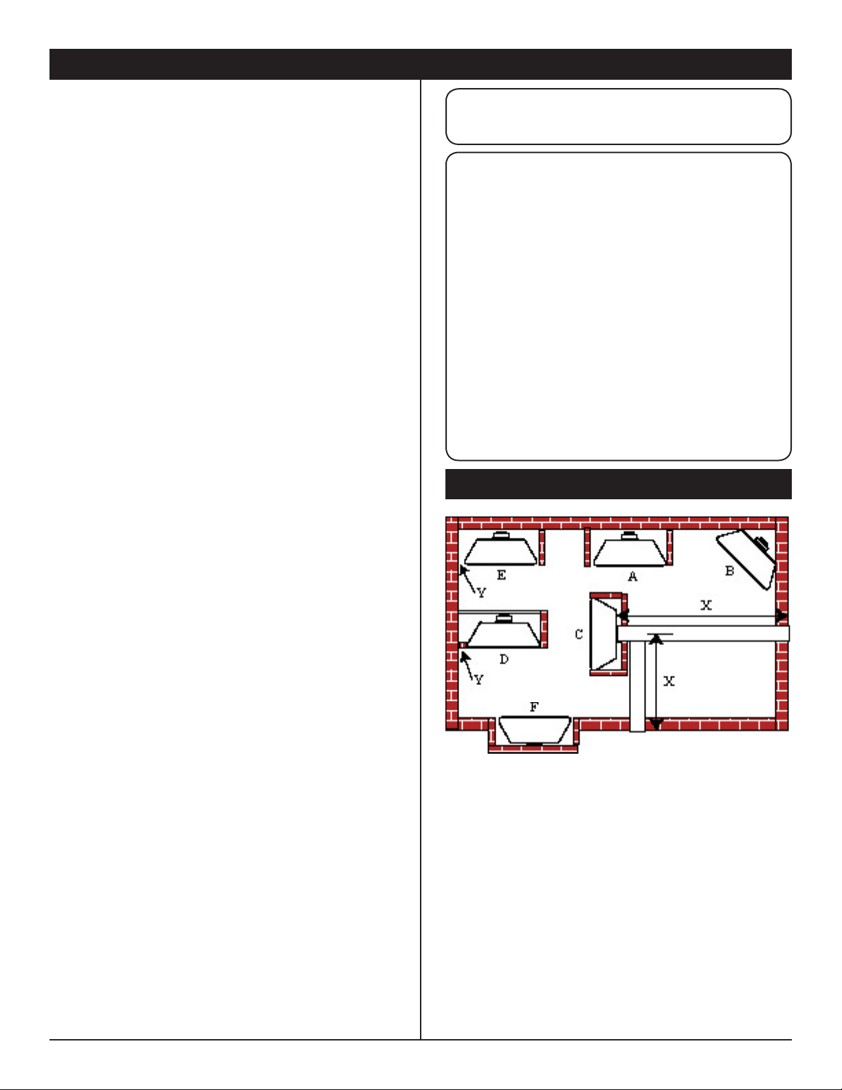
LOCATING YOUR FIREPLACE
Fig. 1
A - Flat on the wall B - Cross corner
C - **Island D - *Room divider
E - *at on wall, corner F - Chase Installation
Note:
** Island (C) and room divider (D) installation is possible as
long as he horizontal portion of the vent system (X) does not
exceed 20' (6.1 m). See the venting instructions for details
* When you install the appliance in a room divider (D) or at
in a corner (E) you must have a minimum of 6" (152 mm)
between the edge of the replace and the adjacent wall (Y).
10002823/0 DVR33 3
Vermont Castings, Majestic Products
A
B
C
D
E
F
G
H
I
J
K
L
L
M
N
O
P
Q
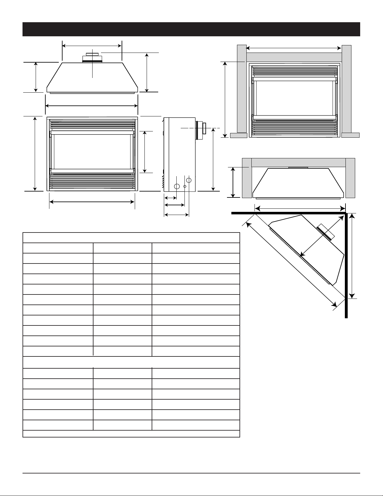
APPLIANCE & FRAMING DIMENSIONS
Appliance Dimensions DVR33
A 838 mm 33"
B 733 mm 28-7/8"
C 416 mm 16-3/8"
D 787 mm 31"
E 560 mm 22-1/16"
F 292 mm 11-1/2"
G 375 mm 14-3/4"
H 622 mm 24-1/2"
I 127 mm 5"
J 191 mm 7-1/2"
K 216 mm 8-1/2"
Framing Dimensions
L 914 mm 36"
M 1295 mm 51"
N 648 mm 25-1/2"
O 305 mm 12"
P 737 mm 29"
Q 851 mm 33-1/2"
4 DVR33 10002823/0
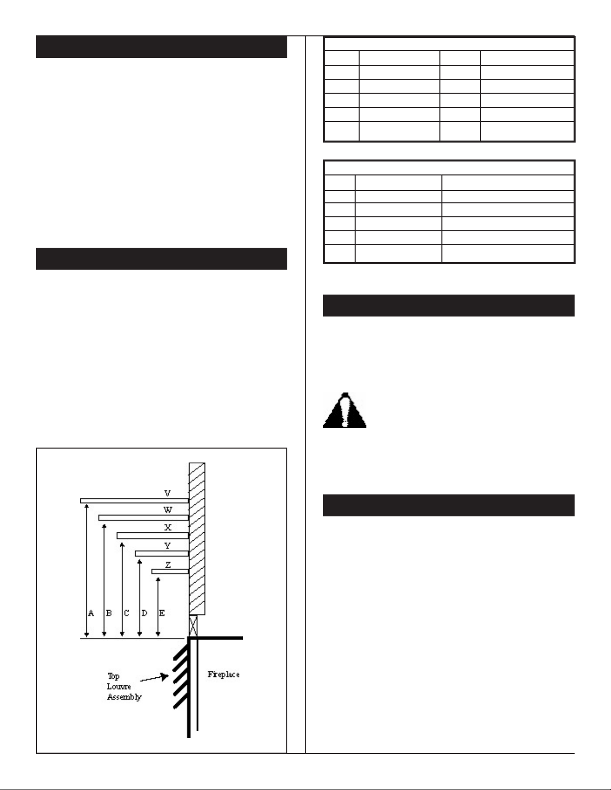
CLEARANCE TO COMBUSTIBLES
Mantel Leg Dimensions (Minimum Width
Ref. Mantel Leg Depth Distance From Edge of Glass
A 10" (254 mm) 10" (254 mm)
B 8" (203) mm) 8" (203 mm)
C 6" (152 mm) 6" (152 mm)
D 4" (101 mm) 4" (101 mm)
E 2" (51 mm) 2" (51 mm)
Mantel Shelf Chart (Minimum Height)
Ref. Mantel Depth Ref. Height above louvre
V 10" (254 mm) A 12" (305 mm)
W 8" (203 mm) B 10" (254 mm)
X 6" (152 mm) C 8" (203 mm)
Y 4" (101 mm) D 6" (152 mm)
Z 2" (50 mm) E 4" (101 mm)
Appliance
Top.................................... 0 mm (0")
Bottom .............................. 0 mm (0")
Vent End ...........................0 mm (0")
Non-vent End.................... 0 mm (0")
Venting
Concentric sections of DV Vent
Top, sides & bottom .........25 mm (1")
Non-concentric sections of DV Vent
Sides and bottom .............. 25 mm (1")
Top.................................... 50 mm (2")
MANTELS
The height that a combustible mantel is installed above the
replace is dependent on the depth of the mantel. This also
applies to the distance between the mantel leg (if tted) and
the replace.
For the correct mounting height refer and widths refer to Fig. 2
and the Mantel Chart below.
The tting of a bay window trim kit does not effect the
distances and reference points referred to in the diagram and
chart.
Non-combustible mantels and legs may be installed at any
height and width around the appliance.
When using paint or lacquer to nish the mantel, such paint
or lacquer must be heat resistant to prevent discolouration.
Vermont Castings, Majestic Products
HEARTH
A hearth is not mandatory but it is recommended for aesthetic
purpose. We recommend a non-combustible hearth which
projects out 12" (305 mm) or more from the front of the
replace.
Cold climate Installation Recommendation:
When installing this unit against a non-insulated exterior wall or chase, it is mandatory
that the outer walls be insulated to conform to
applicable insulation codes.
10002823/0 DVR33 5
FRAMING AND FINISHING
1 Choose the unit location.
2 Place the unit into position and secure it to the oor with
1.5" (38 mm) screws, or nails. The holes to secure the
unit to the oor are located just behind the access door
grille on the left and right side of the unit.
3 Frame in the replace with a header across the top. It is
important to allow for the nished wall face when setting
the depth of the frame.
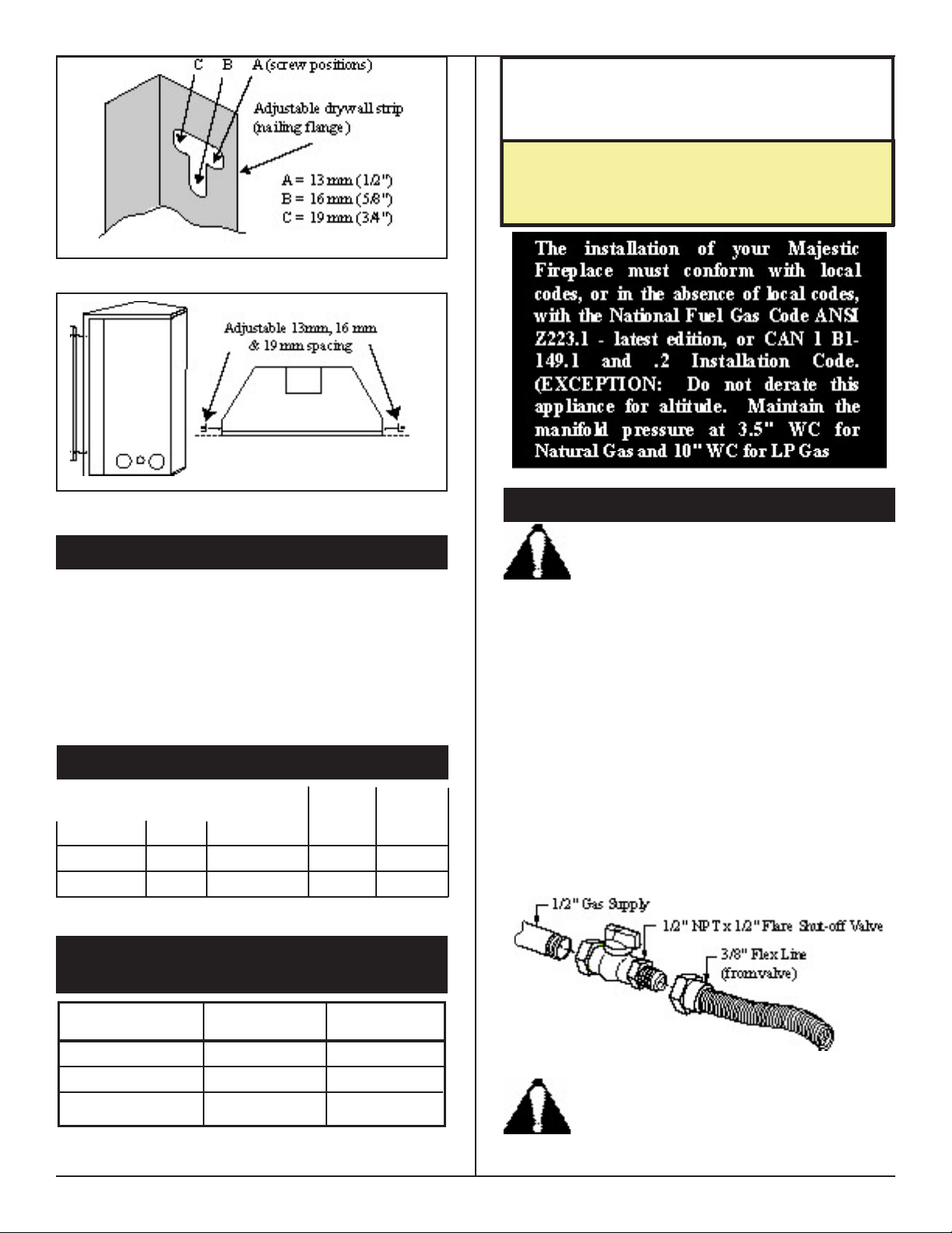
4 Attach the replace to the frame using the adjustable
frame drywall strips (located behind the access door for
shipping). Preset the depth to suit the facing material of
the wall. The strips are adjustable to 1/2"(13 mm), 5/8"
(16 mm) or 3/4" (19 mm), Fig. 3 & 4
5 Screw through the slotted holes in the drywall strip and
into the pre-drilled holes in the replace side. Measure
from the face of the replace to the face of the drywall
strip to conrm the nal depth.
Fig. 2
Vermont Castings, Majestic Products
DVR33
CERTIFIED TO
ANSI Z21.88b-1999 / CSA Z2.33b-M99
Vented Gas Fireplace Heaters
Inlet Minimum
Inlet Maximum
Manifold Pressure
Natural Gas
LP (Propane)
4.5" WC
7" WC
3.5" WC
11" WC
13" WC
10" WC
Fig. 3
Fig. 4
FINAL FINISHING
Non-combustible materials such as brick or tile may be
extended over the edges of the face of the appliance. DO NOT
cover any vent or grille panels.
If a Trim Kit is going to be installed on the replace, the brick
or tile will have to be installed ush with the edges of the
appliance.
GAS SPECIFICATIONS
Max Min
Input Input
Model Fuel Gas Control BTU/h BTU/h
DVR33RN Nat. Millivolt 20,000 14,000
DVR33RP Prop. Millivolt 20,000 15,000
GAS INLET &
MANIFOLD PRESSURES
GAS LINE INSTALLATION
When purging the gas lines, the front glass must
be removed.
The gas pipeline can be brought in through the rear of the
replace as well as the bottom. Knockouts are provided on the
bottom behind the valve to allow for the gas pipe installation
and testing of any gas connection. It is most convenient to
bring the gas line in from the rear right side of the valve as
this allows fan installation or removal without disconnecting
the gas line.
The gas line connection can be made with properly tinned
3/8" copper tubing, 3/8" rigid pipe or an approved ex connector. Since some municipalities have some additional local
codes it is always best to consult your local authority and the
CAN/CGA-B149 (.1 or .2) installation codes.
For U.S.A. Installations consult the current National Fuel Gas
Code, ANSI Z223.1
6 DVR33 10002823/0
Always check for gas leaks with a mild soap and
water solution. Do not use an open ame for
leak testing.
Fig. 5
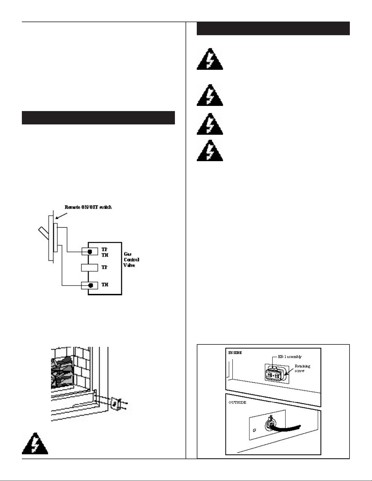
Vermont Castings, Majestic Products
The gas control is equipped with a captured screw type pressure test point, therefore it is not necessary to provide a 1/8"
test point up stream of the control.
When using copper or ex connectors use only approved ttings. Always provide a union when using black iron pipe so
that the gas line can be easily disconnected for burner or fan
servicing, see Fig 5. See the gas specication for pressure
details and ratings.
The replace valve must not be subjected to any test pressures
exceeding 1/2 p.s.i.. Isolate or disconnect this and any other
gas appliance control from the gas line when pressure testing.
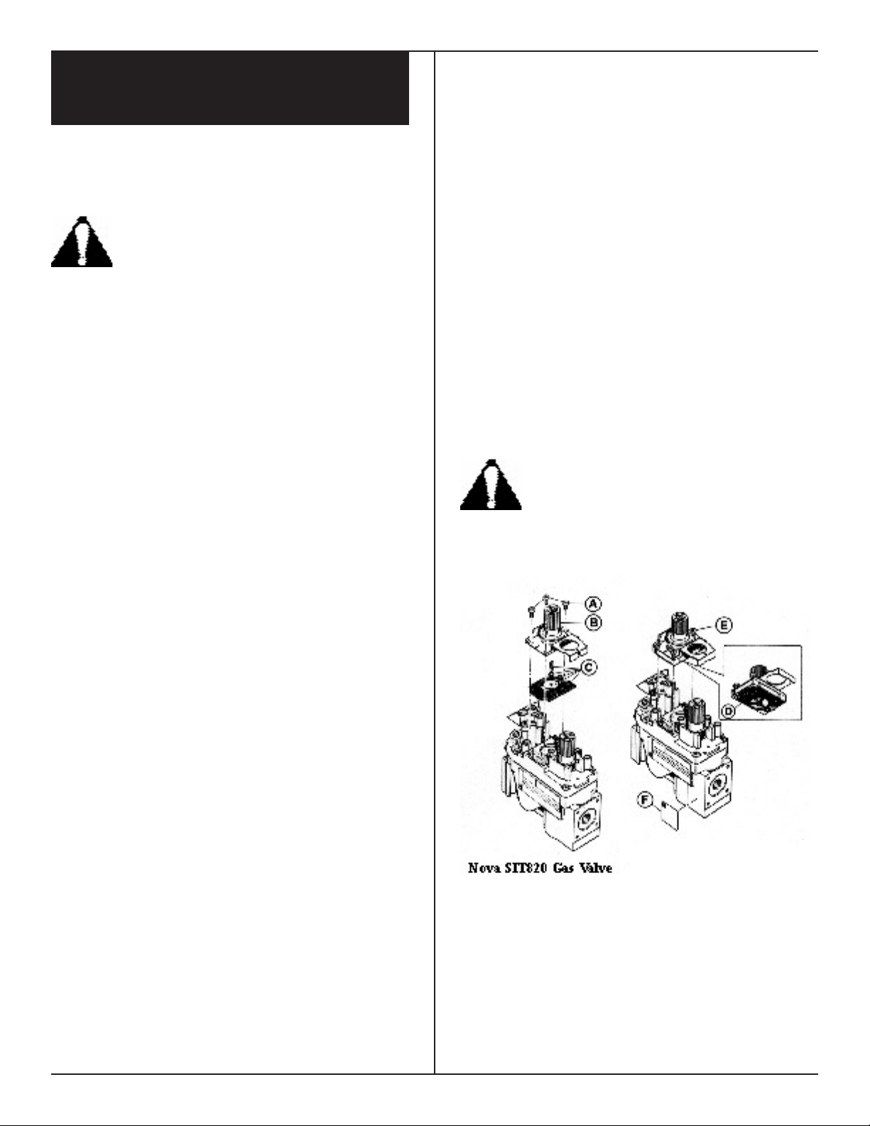
REMOTE ON/OFF SWITCH
Installation
1. Thread the wiring through the holes on the end panels of
the appliance. Take care not to cut the wire or insulation
on metal edges. Route the wire to a conveniently located
receptacle box.
2. Attach the wire to the ON/OFF switch and install the
switch into the receptacle box.
3. Connect the other ends of the wire to the gas control valve
as shown in Fig. 6.
Fig. 6
Alternative Switch Location
The remote switch can be installed on the front/side of the
access door. Simply mount the switch to the bracket provided
and screw the bracket to either side of the frame, lining up the
screws with the pre-punched holes, Fig. 7.
EB-1 ELECTRICAL BOX
The replace, when installed, must be electrically connected and grounded in accordance
with local codes or, in the absence of local
codes, with the current CSA C22.1 Canadian
Electric Code.
For U.S.A. installations follow the local codes
and the national electrical code ANSI/NFPA No
70.
It is strongly recommended that the wiring of
the EB-1 Electrical Junction Box be carried out
by a licensed electrician.
Ensure that the power to the supply line has
been disconnected before commencing this procedure.
The EB-1 Electrical junction box has been supplied standard
on this model to allow for the easy installation of the optional
fan kits.
To connect the EB-1 box to the house electrical supply follow
the steps below.
1. Unscrew the retaining screw from the EB-1 base plate,
Fig. 8 and remove the EB-1 assembly from the appliance
2. Remove the front cover of the EB-1 box.
3. Remove the plug socket assembly from the EB-1 box.
4. Feed the electrical supply line in through the EB-1 opening in the side of the appliance and then through the back
of the EB-1 assembly.
5. Connect the ground wire of the supply line to the green
screw of the socket assembly.
6. Connect the white wire of the power line to the chrome
screw of the socket assembly.
7. Connect the black wire of the power supply line to the
brass screw (polarized) of the socket assembly.
8. Ret the socket assembly back into the electrical box and
replace the cover plate. Secure the cable with the clamp
on the outside of the EB-1 base plate and ret the EB-1
assembly to the appliance with the retaining screw.
Fig. 7
Do not wire the remote ON/OFF switch into any
120 volt power supply
10002823/0 DVR33 7
Fig. 8
Vermont Castings, Majestic Products
CONVERTING THE APPLIANCE
FROM LP TO NATURAL GAS
OR NATURAL GAS TO LP.
This appliance can be converted from Natural Gas to LP gas
(or LP to Natural) with the use of an approved conversion kit.
The kits are specic to individual appliances. Contact your
authorized distributor to obtain the correct kit.
The conversion of this appliance from one gas
to another must be carried out by an authorized
service provider.
1. Disconnect power to the unit and shut off the gas supply.
2. Remove the glass/frame assembly.
3. Carefully remove the logs & lava rock material
4. Remove the screws that are holding the burner housing
in place.
5. Remove the burner housing. Depending on the model of
the appliance you may have to loosen the pilot bracket
retaining screw/nut to allow the pilot and bracket assembly to tilt and give enough clearance to remove the burner
housing.
6. Remove the front and rear orice and replace them with
the corresponding orice supplied in the conversion kit.
That is, use the orice with the smallest hole (from the
kit) to replace the orice with the smallest hole (from the
appliance). Similarly, use the larger orice in the kit to
replace the larger orice in the appliance.
7. SIT Top Convertible Pilot
Gently lift off the pilot hood from the pilot. (Do not
remove the spring clip holding the hood in place). Using
a correctly sized Allen key unscrew the exposed orice.
Insert the new orice supplied in the kit, do not over
tighten the orice. Replace the pilot hood ensuring the
index tab aligns with the notch on the hood.
PSE Pilot
Using a suitable wrench on the hexagonal body unscrew
the pilot hood assembly from the pilot, do not twist the
hood itself. Remove the orice and replace it with the
new orice supplied in the kit. Ret the pilot hood
assembly. Do not over-tighten the pilot hood. The hood
must return to its original alignment. Take care not to
damage the thermocouple, thermopile or igniter.
8. SIT 820 NOVA Gas Control Valve (Fig. 9)
a) Using a Torx T20 or slotted screwdriver, remove and
save the three pressure regulator mounting screws (A),
pressure regulator tower (B) and diaphragm (C).
b) Ensure the rubber gasket (D) is properly positioned and
install the new Hi/Lo pressure regulator to the valve using
the new screws (E) supplied with the kit. Tighten screws
securely. (Reference torque - 25 in.Lb).
c) Install the enclosed identication label (F) to the valve
body where it can be easily seen.
Honeywell Gas Control Valve (Fig. 10)
The Honeywell valve tted to this unit is suitable for use
with LP or Natural Gas. It is converted to the required gas
application by the installation of a colour coded "conversion screw".
a) Using a suitable small screwdriver lift out the central
regulator cap from the 'Hi - Lo' knob on the valve.
b) Unscrew the exposed 'conversion screw'.
c) Insert the new colour coded 'conversion screw'. Do not
over-tighten the screw, it must be nger tight.
d) Ret the regulator cap.
e) Mount the conversion label supplied with the conver-
sion screw to the valve in a visible position.
9. Reassemble the replace in the reverse order, except for
the front glass. Leave this off until the unit has been
checked for leaks and the gas supply line has been bled.
10. After bleeding the gas line and checking for leaks with a
soap solution, replace the front glass. Fire up the unit,
check for ame impingement on the logs, adjusting them
if necessary. Check the manifold and supply pressures
against the appliance specications.
The procedure for converting from one gas to
another is the same regardless of the initial gas
used. The only variation is in the orice sizes
and component part numbers. Your authorized
service provider will ensure the correct parts are
used.
Fig. 9
8 DVR33 10002823/0
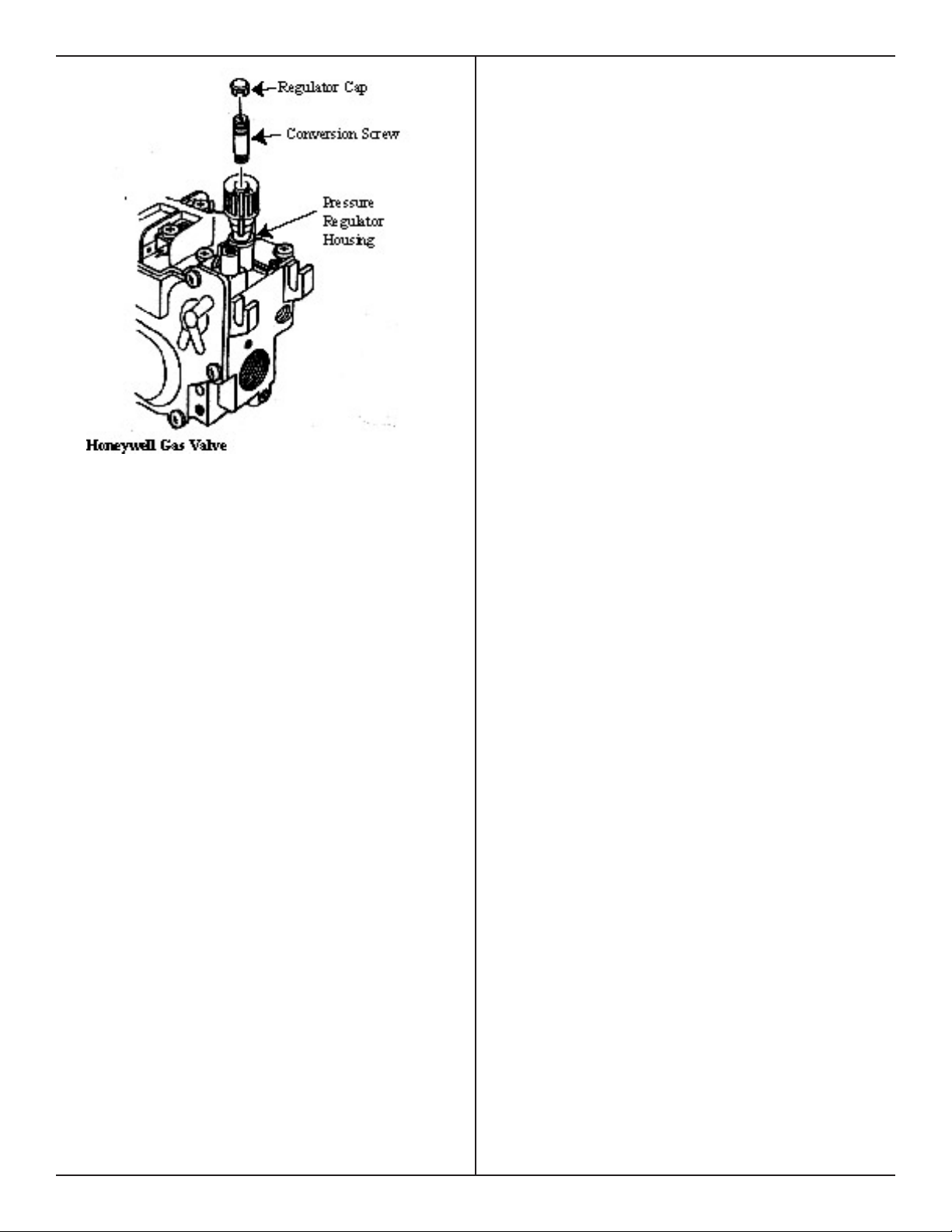
Fig. 10
Vermont Castings, Majestic Products
10002823/0 DVR33 9
Vermont Castings, Majestic Products
V
V
V
V
V
V
V
V
V
X
X
X
D
E
B
B B
C
B
M
B
A
J
K
A
F
L
G
G
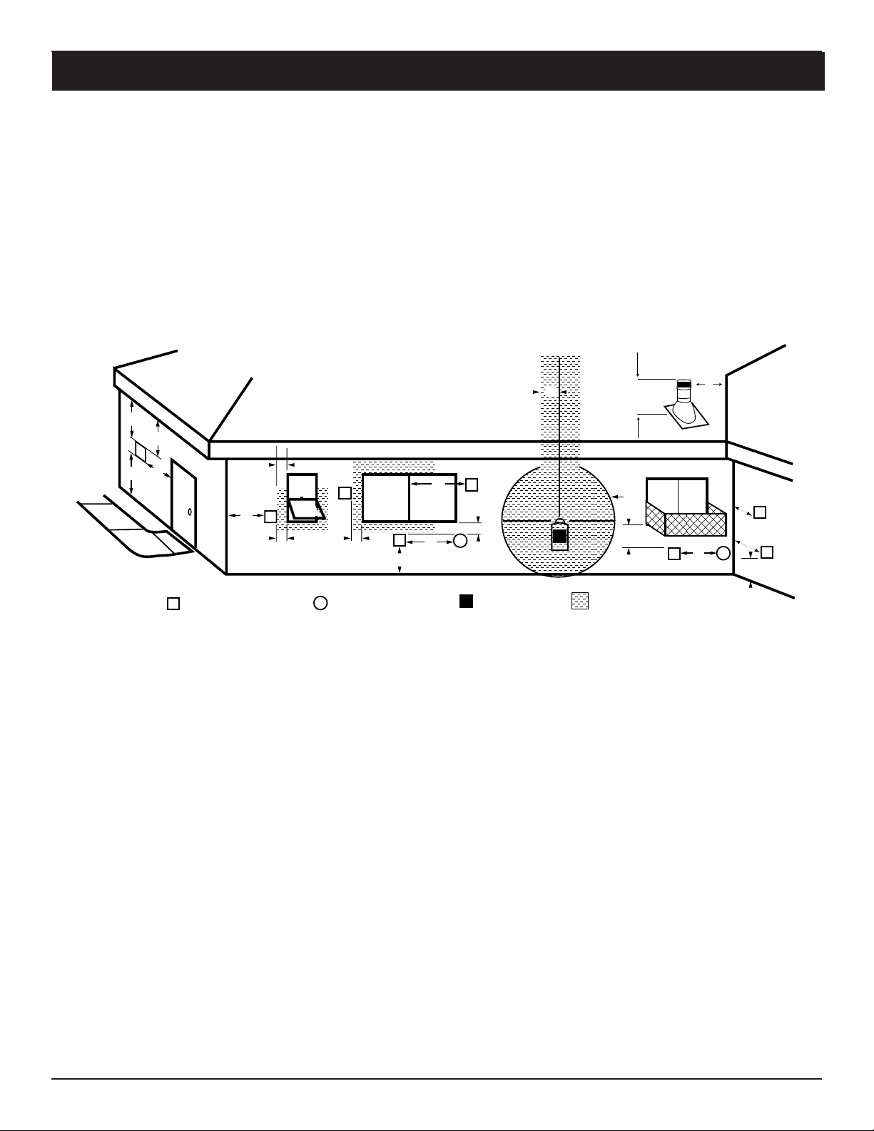
TERMINATION CAP AIR SUPPLY INLET GAS METER RESTRICTED AREA
(TERMINATION PROHIBITED)
H
I
Fixed
Closed
Fixed
Closed
O
p
e
n
a
b
l
e
Openable
Fixed
Closed
G
G
N
N
GENERAL VENTING INFORMATION — TERMINATION LOCATION
Your replace is approved to be vented either through the side
wall, or vertically through the roof.
– Only venting components specically approved and
labelled for this replace may be used.
– Minimum clearances between vent pipes and combusti-
ble materials is one (1") inch (25 mm).
– Venting terminals shall not be recessed into a wall or
siding.
– Horizontal venting must be installed on a level plane
without any incline or decline.
There must not be any obstruction such as bushes, garden sheds,
fences, decks or utility buildings within 24" from the front of the
termination hood.
Do not locate termination hood where excessive snow or ice
build up may occur. Be sure to check vent termination area
after snow falls, and clear to prevent accidental blockage of
venting system. When using snow blowers, make sure snow is
not directed towards vent termination area.
Location of Vent Termination
It is imperative that the vent termination be located observing
the minimum clearances as shown on this page.
*Check with local codes or in absence of same with CAN/
CGA B149 (.1 or .2) Installation Codes (1991) for Canada or
for U.S.A. Installations follow the current National Fuel Gas
Code, ANSI Z223.1.
A = clearance above grade, veranda, porch, deck, or bal-
cony [* 12 inches (305mm) minimum]
B = clearance to window or door that may be opened [12"
(306mm)].
C = clearance to permanently closed window [minimum 12
inches (305mm) recommended to prevent condensation
on window]
D = vertical clearance to ventilated soft located above
the terminal within a horizontal distance of 24 inches
(610mm) from the centre-line of the terminal [18 inches
(458mm) minimum]
E = clearance to unventilated soft [12 inches (305mm) min-
imum].
F = clearance to outside corner see next page
G = clearance to inside corner see next page
H = * not to be installed above a meter/regulator assembly
within 36 inches (914mm) horizontally from the centre-
line of the regulator
† a vent shall not terminate directly above a side-walk or paved driveway which is located between two single
family dwellings and serves both dwellings *
‡ only permitted if veranda, porch, deck, is fully open on a minimum 2 sides beneath the oor *
* as specied in CAN/CGA B149 (.1 or .2) Installation Codes (1991) for Canada or for U.S.A. Installations follow
the current National Fuel Gas Code, ANSI Z223.1.
Note: Local codes or regulations may require different clearances.
I = clearance to service regulator vent outlet [*72 inches
(1828mm) minimum]
J = clearance to non-mechanical air supply inlet to building
or the combustion air inlet to any other replace [ *12
inches (305mm) minimum]
K = clearance to a mechanical air supply inlet [* 72 inches
(1828mm) minimum]
L = † clearance above paved side-walk or a paved driveway
located on public property [*84 inches (2133mm) minimum]
M = clearance under veranda, porch, deck [*12 inches
(305mm) minimum ‡]
N = Clearance above a roof shall extend a minimum of 24"
(610mm) above the highest point when it passes through
the roof surface, and any other obstruction within a
horizontal distance of 18" (450mm).
10 DVR33 10002823/0
 Loading...