

Page 1
DV36/39 STKP and
CBTK
Bay Front Kits
Installation Instructions
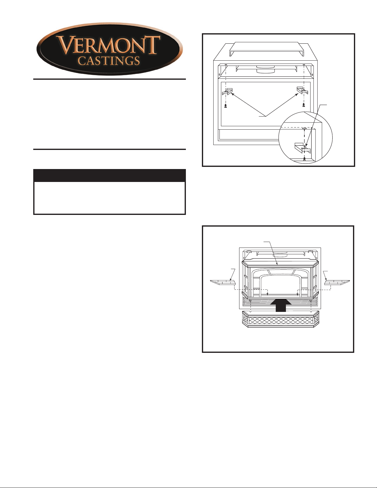
Top Hanger
Brackets
Use the
outermost
hole
Please read these instructions before beginning
assembly.
Caution
Porcelain enamel is fragile. The finish can be easily damaged if castings are not handled carefully.
Always place castings on a protective surface, such
as a towel, blanket or carpet.
Carefully unpack the Front Face components and inspect for damage. Report missing or damaged parts to
your dealer immediately.
Kit Contents
• Upper Grille Assy. • Base Grille Assy.
• Window Assy. • Base Trim Piece
• Hanger Brackets, 2 • Knob Ext., Hi/Lo
• Knob Ext., Philostat • Knob Ext., Piezo
• Knob, Off/On Ext. SIT#916.188
• Knob, HI/LO Ext., SIT#916.189
• #10 x 1/2” sheet metal screws, 2
• Ceramic Refractory, 2
You will need a Phillips screwdriver to install the front.
The fireplace installation should be complete and in
spected. Any surround and trim assemblies should also
be installed before setting the front face in position.
-
Installation
1. Remove the upper louvre section from the DV firebox front.
2. Fasten the two top brackets at the existing holes in
the upper inside lip of the firebox. Use the left hole
on the left bracket and the right hole on the right
bracket. (Fig. 1)
3. Place two (2) ceramic refractory pieces into window
assembly. (Fig. 2) CAUTION: The ceramic refractory
pieces are very fragile, handle with care!
KT232
Fig. 1 Be sure that each of the steel brackets is securely attached to the fireplace frame.
4. Hang the window panel on the firebox front by engaging its upper rail over the back of the top of the
firebox opening frame. (Fig. 2)
• Remove the protective film from the brass trim
sections, if applicable.
Upper Rail
Ceramic
Refractory
Fig. 2 Cast window panel shown, Steel window mounts in the
same manner.
5. The base trim piece is used to close a gap that might
exist between the base grille and a lower hearth.
Attach the trim section to the base grille by engaging
the narrow flange to the clips on the underside of the
base grille. (Fig. 3)
Ceramic
Refractory
KT233
30000429 8/08 Rev. 4
Page 2
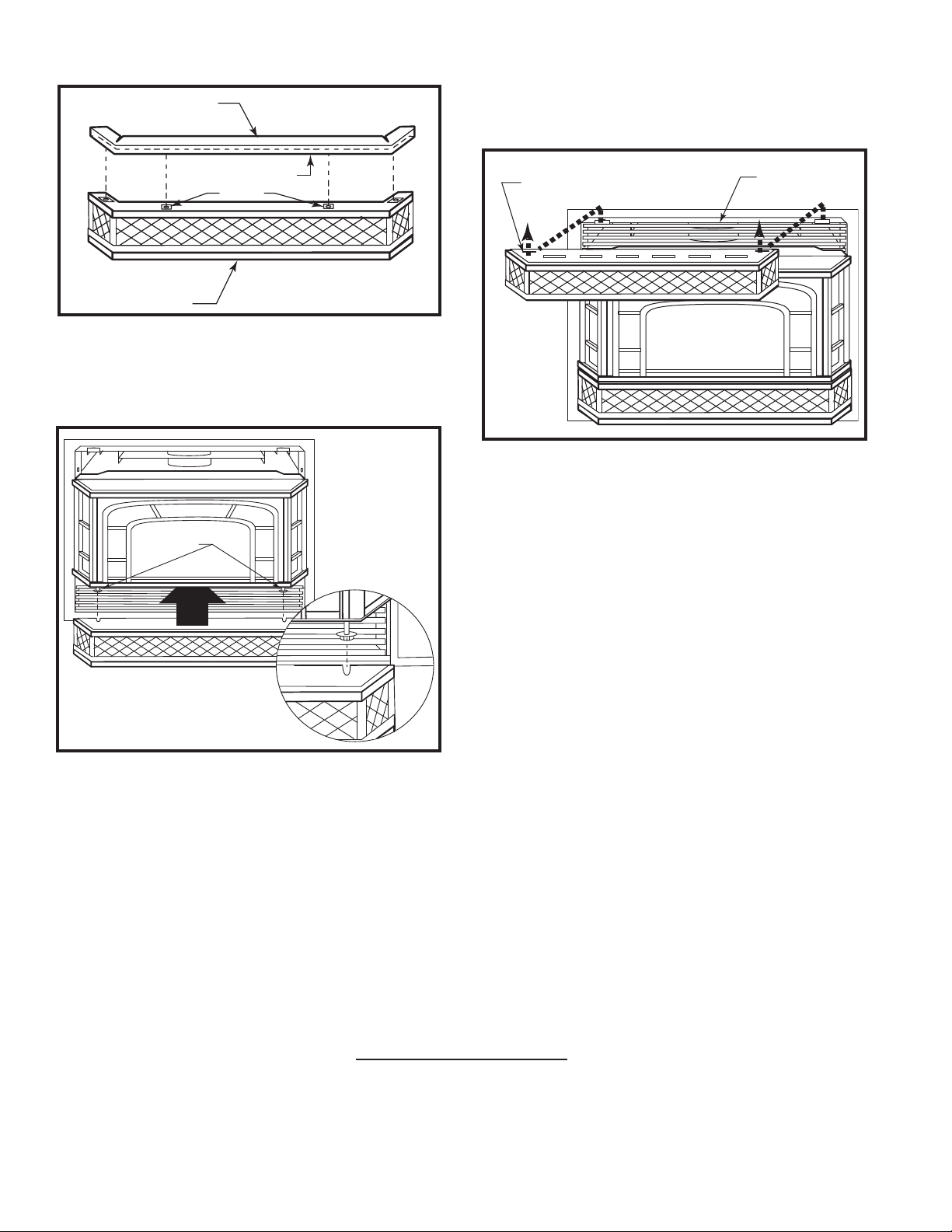
Trim Piece
7. Replace the upper louvre panel.
8. Hang the top grille on the upper brackets at the two
slots as shown in Figure 5.
Narrow Flange
Clips
Base
KT234
Fig. 3 Base and trim piece shown upside down.
6. Attach the cast iron base grille to the bottom of the
window assembly by engaging the fender washers
with the slots on the base. (Fig. 4)
Fender
Washers
Mounting Slot
KT236
Fig. 5 Attach top grille.
Upper Louvre
Panel
Base Grille
KT235
Fig. 4 Install base grille using fender washers.
MHSC
149 Cleveland Drive • Paris, Kentucky 40361
www.mhsc.com
 Loading...