

Page 1
Electric Fireplace
™
Model
DEF33CE
Installation Instructions & Homeowner's Manual
WARNING! IF THE INFORMATION IN THIS MANUAL IS NOT FOLLOWED EXACTLY, AN
ELECTRICAL SHOCK OR FIRE MAY RESULT CAUSING PROPERTY DAMAGE,
PERSONAL INJURY OR LOSS OF LIFE.
FOR YOUR SAFETY
DO NOT STORE OR USE GASOLINE OR OTHER
FLAMMABLE VAPOURS AND LIQUIDS IN THE
VICINITY OF THIS OR ANY OTHER APPLIANCE.
The Vermont Castings,
Majestic Products Company
410 Admiral Blvd. • Mississauga, Ontario • Canada L5T 2N6
www.vermontcastings.com • www.majesticproducts.com
INSTALLER: DO NOT DISCARD THIS MANUAL - LEAVE FOR HOMEOWNER
- 1 -
10003014
11/00 Rev. 0
Page 2

TABLE OF CONTENTS
Please read the Installation & Operating Instructions before using this appliance.
Thank you and congratulations on your purchase of a Majestic fireplace.
IMPORTANT: Read all instructions and warnings carefully before starting installation. Failure to follow these instructions
may result in a possible electric shock, fire hazard and/or injury and will void the warranty.
Installation Instructions 3
General Information .................................................................................................... 3
Locating your Fireplace............................................................................................... 3
Fireplace Dimensions.................................................................................................. 4
Electrical Specifications .............................................................................................. 4
Mantels ................................................................................................................ 5
Clearance to Combustibles ......................................................................................... 5
Framing & Finishing .................................................................................................... 5
Final Finishing ............................................................................................................. 5
Hearth ................................................................................................................ 5
Cabinet Installation...................................................................................................... 6
Electrical Connection .................................................................................................. 6
Installation of Logs ...................................................................................................... 6
Service Instructions 7
Louvre Removal .......................................................................................................... 7
Glass Frame Removal ................................................................................................ 7
Glass Information ........................................................................................................ 7
Replacing Light Bulbs ................................................................................................. 7
Maintenance of Motors................................................................................................ 8
Cleaning Brass Trim.................................................................................................... 8
Electrical Diagram ....................................................................................................... 8
Operating Instructions 9
On/Off Switch .............................................................................................................. 9
Heater Control............................................................................................................. 9
Log Illumination Control .............................................................................................. 9
Flame Speed Control .................................................................................................. 9
Control Panel .............................................................................................................. 9
Replacement Parts Pictorial 10
Replacement Parts List ............................................................................................. 11
Options 12
- 2 -
Page 3

INSTALLATION INSTRUCTIONS
GENERAL
1 . Read all instructions before using this appliance.
2. This appliance is hot when in use. To avoid burns, do
not let bare skin touch hot surfaces. If provided, use
handles when moving this appliance. Keep combustible materials, such as furniture, pillows, bedding,
papers, clothes and curtains at least 3 feet (1m) from
the front of this appliance.
3. CAUTION: Extreme caution is necessary when any
heater is used by or near children or invalids and
whenever the heater is left operating and unattended.
4. If possible, always unplug this appliance when not in
use.
5. Do not operate any heater with a damaged cord or plug
or after the appliance malfunctions, or if it has been
dropped or damaged in any manner.
6. Any repairs to this fireplace should be carried out by a
qualified service person.
7. Under no circumstances should this fireplace be modified. Parts having to be removed for servicing must be
replaced prior to operating this fireplace again.
16.This appliance has hot and arcing or sparking parts
inside. Do not use it in areas where gasoline, paint or
flammable liquids are used or stored. This fireplace
should not be used as a drying rack for clothing, nor
should Christmas stockings or decorations be hung in
the area of it.
17.Use this appliance only as described in this manual.
Any other use not recommended by the manufacturer
may cause fire, electric shock or injury to persons.
18.Avoid the use of an extension cord because the
extension cord may overheat and cause a risk of fire.
However, if you have to use an extension cord, the
cord shall be No. 16 AWG minimum size and rated not
less than 2500 Watts. The extension cord must be a
three wire cord with grounding type plug and cord
connection.
19.This appliance must not be located immediately below
a socket-outlet.
20.SAVE THESE INSTRUCTIONS.
8. Do not use outdoors.
9. This heater is not intended for use in bathrooms,
laundry areas and similar indoor locations. Never
locate this appliance where it may fall into a bathtub or
other water container.
10.Do not run cord under carpeting. Do not cover cord
with throw rugs, runners or the like. Arrange cord away
from traffic areas and where it will not be tripped over.
11.To disconnect this appliance, turn controls to the off
position, then remove plug from outlet.
12.Connect to properly grounded outlets only.
13. This appliance, when installed must be electrically
grounded in accordance with local codes.
14. Do not insert or allow foreign objects to enter any
ventilation or exhaust opening as this may cause an
electric shock or fire, or damage the appliance.
15.To prevent a possible fire, do not block air intakes or
exhaust in any manner. Do not use on soft surfaces,
like a bed, where openings may become blocked.
LOCATING YOUR
MAJESTIC
ELECTRIC FIREPLACE
Your new fireplace may be installed into an existing
masonry or zero clearance fireplace. It may also be
installed using a prefabricated cabinet available from
your dealer or be built into a wall.
When choosing a location for your new fireplace, ensure
that the general instructions are followed. Also, for best
effect install the fireplace out of direct sunlight.
- 3 -
Page 4
FIREPLACE DIMENSIONS
RED
BLACK
11
POTENIOMETER
DRUM
MOTOR
2
12
SPEED CONTROL
FAN
MOTOR
10
HEATER ELEMENT
3 BLACK
1 BLACK
2 WHITE
4 WHITE
9
8
11
3
DIMMER
4
5
9
8
14 WHITE
6 WHITE
5 BLACK
13 BLACK
THERMO STAT
6
8 WHITE
11
8
9 RED
10 BLACK
11 YELLOW
7 BLACK
8 WHITE
5 BLACK
6 WHITE
8 RED
7
11 YELLOW
12
11
14
13
A 33" 838mm
B 28
C 16
7/8"
3/8"
733mm
416mm
D 31" 787mm
E 17" 430mm
F 11
1/2"
292mm
G 3" 76mm
M 36" 914mm
N 51" 1295mm
O 25
1/2"
648mm
ROD 12" 305mm
ROW 33
ROH 29
ELECTRICAL SPECIFICATIONS
Voltage: 240VAC, 50Hz
Total Amps: 9.5 Amps
Total Watts: 2250 Watts
Heater Rating: 2000 Watts
1/2"
5/8"
851mm
752mm
Fig. 1
- 4 -
Page 5

MANTELS
Depending on the width of the mantel it may be installed
higher or lower from the top of the louvre opening. See
drawing and chart below for proper installation height of
your combustible mantel piece. Non-combustible mantels
may be installed at any height above the appliance opening.
When using paint or lacquer to finish the
mantel, such paint or lacquer must be heat
resistant to prevent discolouration.
CLEARANCE TO COMBUSTIBLES
Sides ....... 0 mm/0 inches
Sides ....... 0mm/0 inches
Floor........ 0 mm/0 inches
Top.......... 0 mm/0 inches
FRAMING AND FINISHING
V
1. Choose fireplace location.
2. Place fireplace into position.
3. Frame in fireplace with a header across the top. It is
W
important to allow for finished face when setting the
depth of the frame.
X
WALL
A
B
C
D
Y
Z
Non-combustible materials such as brick and tile can be
extended over the face of the unit (Do not cover louvres
FINAL FINISHING
or glass door). If a Trim Kit is going to be installed, brick
E
and tile will have to be installed flush with the side of this
appliance.
TOP
LOUVRE
OPENING
FRONT GLASS
SIDE VIEW
OPTIONAL
HEARTH
A hearth is not mandatory but it is recommended for
aesthetic purposes. We recommend a non-combustible
HEARTH
hearth which does not obstruct louvre opening.
Cold climate installation recommendation:
Fig. 2
When installing this unit against a noninsulated exterior wall or chase, it is
mandatory that the outer walls be insulated
to conform to applicable insulation codes.
MANTEL CHART
Ref. Mantel & Leg Ref. Mantel From Mantel Leg from
Depth Top Louvre Fireplace Side
(Maximum) (Minimum) (Minimum)
V 10" (254 mm) A 12" (305 mm) 10" (254mm)
W 8" (203 mm) B 10" (254 mm) 8" (203mm)
X 6" (152 mm) C 8" (203 mm) 6" (152mm)
Y 4" (101 mm) D 6" (152 mm) 4" (101mm)
Z 2" ( 51 mm) E 4" (101 mm) 2" (51mm)
- 5 -
Page 6

CABINET INSTALLATIONS
INSTALLATION OF LOGS
Cabinets are available from your dealer which allow for
fast, convenient installation of your fireplace against existing walls.
ELECTRICAL CONNECTION
A 15 AMP, 240 Volt, 50 Hz circuit with a properly grounded
outlet is required. Preferably, the fireplace will be on a
dedicated circuit as other appliances on the same circuit
may cause the circuit breaker to trip or the fuse to blow
when the heater is in operation. The unit comes standard
with a 7 ft. (2134 mm) long three wire cord, exiting the right
side of the fireplace. Plan the installation to avoid the use
of an extension cord. If an extension cord must be used,
it must be a minimum 16AWG, three wire with grounding
type plug and connector and rated not less than 2500
Watts.
A new electrical outlet can be installed inside the frame
construciton, if permitted by local codes.
Electrical outlet wiring must comply with
local building codes and other applicable
regulations to reduce the risk of fire,
electrical shock and injury to persons.
1. Turn off power to the unit.
2. Remove front glass (See "Glass Removal" section).
3. Remove logs from packaging.
4. The ember bed is shipped in place. No adjustment is
necessary.
5. Install rear left log (A15). Use notches to have a proper
location.
6. Install rear right log (A16). Use notches to have a
proper location.
7. Install front left log (A13). Use notches to have a
proper location.
8. Install front right log (A14). Use notches to have a
proper location.
Fig. 6
Do not use this fireplace if any part of it has
been under water. Immediately call a
qualified service technician to inspect the
fireplace and replace any part of the
electrical system which has been under
water.
Hard (Direct) Wire Connection
If desired, a qualified electrician may remove the cord
conection and wire this unit directly to the household
wiring.
Any electrical re-wiring of this appliance
must be done by a qualified electrician.
WARNING: Safe use plug must be
accessible after installation.
WARNING: This appliance is fitted with a
non-rewireable plug. If it’s necessary to
change the fuse in a plug. The fuse cover
must be refitted. If the fuse cover is lost or
damaged, the plug must not be used until it
is replaced. It is important that the colour of
the replacement fuse cover corresponds
with the colour markings on the base of the
plug. An ASTA approved BS1362 fuse rated
at 13A should be used.
CfM125
- 6 -
Page 7

SERVICE INSTRUCTIONS
Disconnect power before attempting any
maintenance or cleaning to reduce the risk
of fire, electrical shock or personal injury.
LOUVRE REMOVAL
To remove top louvre pull louvre up and then lift out.
See Figure 7.
2.
GLASS INFORMATION
1. Under no circumstances should this product be
operated with missing or broken glass.
2. Do not strike or slam the glass.
3. Do not use abrasive cleaners to clean the glass.
4. This product uses tempered glass. Replacement of
the glass with gasket as supplied by the manufacturer should be done by a qualified service person.
LOUVRE
1.
GLASS
PANEL
Fig. 7
GLASS FRAME REMOVAL
1. Turn off electrical supply to unit.
2. Let fireplace cool if it has been operating.
3. Remove top louvre. (See Louvre Removal).
4. Open lower louvre assembly.
5. Remove two door retention screws along lower edge
of door frame.
6. Swing lower portion of door out from the fireplace
and gently lift up to disengage top of door from
fireplace. See Fig. 8.
7. To reinstall glass door, follow the above procedure in
reverse.
GLASS
FRAME
SCREWS
CLAMPS
FIREPLACE
FRONT
REPLACING LIGHT BULBS
This fireplace uses four clear 240 Volt, 50 Hz, 60 Watts,
E-14 socket base light bulbs (chandelier candle type).
Three of the lights are located under the ember bed of
the unit. The fourth light is found at the top of the firebox
above the log set. For convenience, if one of the bulbs
burns out, it may be a good idea to replace all of the light
bulbs.
Do not exceed 60 Watts per bulb. Use of
higher rated bulbs may result in a fire,
causing property damage, personal injury
or loss of life.
1. Turn off power to the unit.
2. Let fireplace cool if it has been operating.
3. Remove top louvre. (See Louvre Removal).
4. Remove glass door. (See Glass Frame Removal).
5. Gently remove log set.
6. Remove the two screws securing the ember bed in
position. One screw is located on either side of the
ember bed near the front.
7. Examine the bulbs to determine which bulbs need to
be replaced.
8. While holding the socket, unscrew the defective
bulb(s).
9. Install the new light bulb(s) by screwing in while
holding the socket.
10. Reinstall ember bed, log set, glass door and top
louvre.
WINDOW
FRAME
WINDOW
FRAME
SCREWS
Fig. 8
- 7 -
Page 8

MAINTENANCE OF MOTORS
CLEANING BRASS TRIM
The motors used on the fan and the drum assembly are
prelubricated for extended bearing life and require no
further lubrication. However, periodic cleaning/vacuuming
of the fan/heater is recommended.
Clean the brass trim using a soft cloth, slightly dampened
with lemon oil and buff with a clean soft cloth. Do NOT use
brass polish or household cleaners as these products will
damage the brass trim. Lemon oil can be obtained at
supermarkets or hardware stores.
Make sure that the power is turned off
before proceeding.
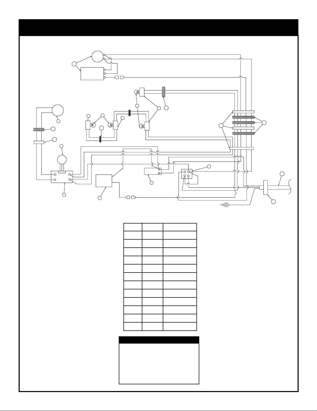
ELECTRIC DIAGRAM
Any electrical repairs or rewiring of this unit should be carried out by a licensed electrician in accordance with national and
local codes
If repairing or replacing any electrical component or wiring the original wire routing, colour coding and
securing locations must be followed.
FAN
MOTOR
10
HEATER ELEMENT
9 RED
10 BLACK
11 YELLOW
7 BLACK
8 WHITE
DRUM
RED
MOTOR
2
11
12
3
POTENIOMETER
BLACK
SPEED CONTROL
9
8
11
1 BLACK
2 WHITE
DIMMER
10003167
4
5
CFM Majectic Factory Wire Req'd
2. Motor Variable Speed (12V/DC)
3. potentiometer
4. Speed Control
5. Dimmer Switch Rotary
6. Thermostat
7. On / Off Switch
8. Light Socket
9. Light Bulb
10. Fan/Heater
11. Nylon Cable Tie
12. Grommet 7/8
3 BLACK
4 WHITE
8
9
14 WHITE
6 WHITE
5 BLACK
13 BLACK
THERMO STAT
6
8 WHITE
11
8
5 BLACK
6 WHITE
8 RED
Wiring Colour Code:
WH = White
BL = Black
RE = Red
- 8 -
7
11 YELLOW
12
11
14
13
Page 9

OPERATING INSTRUCTIONS
The control compartment is located behind the lower louvre
panel. To access the controls, simply flip down the lower
louvre panel. To locate the position of each control described below, refer to Fig. 9.
1. MAIN ON/OFF SWITCH
The On/Off switch supplies power to all of the functions of
the fireplace. This is an illuminated switch which normally
will light up when in the "on" position.
During any service of this appliance, the
power to the unit must be turned off. It
is not acceptable to use the "On/Off"
switch to meet this requirement.
2. HEATER CONTROL
The Heater Control acts to turn the heater on and off as well
as setting the comfort level in the room. Turning the knob
clockwise from the off position will place the heater into
operation. The further the knob is rotated clockwise, the
higher the set point temperature. Turning the knob
counterclockwise will lower the set point temperature.
Turning it all the way counterclockwise will turn the heater
function off.
The Heat Hi/Lo Switch is located beside the On/Off switch.
When the Heat Hi/Lo Switch indicates the Off position the
heat is on Low (single state heat). When the Heat Hi/Lo
Switch indicates the On position the Heat is on High (full
state heat)
3. LOG ILLUMINATION CONTROL
This control varies the brightness of the light located above
the log set. Turn the knob to increase, decrease or turn off
the light as desired.
See Installation Instructions for service
details.
WARNING: Disconnect Power Before
Servicing.
WARNING: Risk of fire, keep electrical
cords, draping, and other furnishings at
least 3 feet (0.9m) from the front of the
heater.
4
4. FLAME SPEED CONTROL
Turn the flame speed control knob to increase or decrease
the flame speed as desired.
CONTROL PANEL
3
2
1
Voir les instructions d'installation pour
des details sur le service.
AVERTISSEMENT: Debrancher la source
d'alimentation avant le service.
AVERTISSEMENT: Risque d'incendie,
veiller a ce que les cordons electriques,
tentures et autres textiles domestiques
soient a au moins 3 pieds (0,9m) de
I'avant de I'appareil de chauffage.
10003011
Fig. 9
- 9 -
Page 10

REPLACEMENT PARTS - ELECTRIC FIREPLACE
- 10 -
Page 11

REPLACEMENT PARTS LIST - ELECTRIC FIREPLACE
DESCRIPTION PART NO.
1. Log Set Complete 10001682
1a. Log Ember Bed A12
1b. Log Front Left A13
1c. Log Front Right A14
1d. Log Rear Left A15
1e. Log Rear Right A16
2. Fan/Heater Assembly w/bracket 10003009
3. Motor 12VDC - Flame genertor 10001978
4. Electrical Cord 8 ft. Assembly 10003144
5. On/Off Switch 10002998
6. Thermostat - Heater Control 10002987
7. Switch - Log Illumination Dimmer Assembly 10003143
8. Potentiometer - Flame Speed Control 10001168
9. Circuit Board - Flame Speed Control 10002983
10. Knob - Flame Speed, Heater Controls & Potentiometer 10001639
11. Top Louvre Assembly 10000292
12. Bottom Louvre Assembly 10000293
13. Hinge Access Door 52356
14. Trim-Frame Window (PB) (w/2 magnets) 55005
15. Light Filter - Ember Bed (Not Shown) 10001259
16. Light Diffuser Screen (Not Shown) 10001157
17. Screen Tinted Plastic (Not Shown) 10001263
18. Glass with Gasket 10001883
19. Gasket Glass 10001881
20. Frame Window 10001729
21. Light Diffuser - ember Bed (not shown) 10001536
22. Flame Generator Assembly 10001223
23. Light Diffuser - Ember Bed (Not Shown) 10001536
24. Light Socket 10003003
25. Facial Control Assembly 10003034
- 11 -
Page 12

OPTIONS
Description Order Part Number
Trim Kit - Polished Brass DV33TKP (Fitting instructions included in kit)
Medium Trim Kit - Polished Brass DV33TKMP (Fitting instructions included in kit)
Wide Trim Kit - Polished Brass DV33TKWP (Fittng instructions included in kit)
Bay Window Trim Kit - Polished Brass DV33BTKP (Fitting instructions included in kit)
Ceramic Refractory Kit DEF33CR (see below for fitting instructions)
1. Remove glass door assembly.
CERAMIC
REFRACTORY
INSTALLATION
2. Slide refractory panels on either side of the firebox between firebox side and the upper
lintel baffle.
3. Push panels against firebox side. If desired, secure the panels to the sides of the
firebox with some adhesive, such as silicone.
4. Replace glass frame and upper louvre panel.
- 12 -
 Loading...